
Create successful ePaper yourself
Turn your PDF publications into a flip-book with our unique Google optimized e-Paper software.
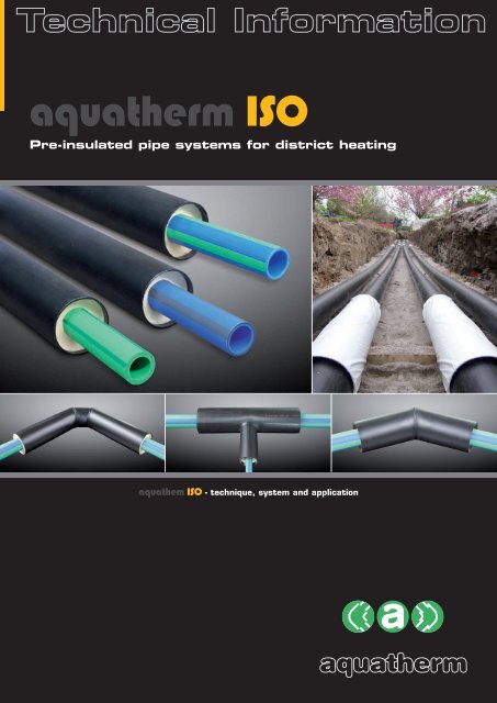
<strong>aquatherm</strong> <strong>ISO</strong><br />
Pre-insulated pipe systems for district heating<br />
aquathem <strong>ISO</strong> - technique, system and application<br />
<strong>aquatherm</strong>
CONTENTS<br />
– Contents 3<br />
Chapter 1:<br />
Features 4<br />
– Pipe system <strong>aquatherm</strong> <strong>ISO</strong> 5<br />
Fields of application<br />
– Medium pipes 6-8<br />
Material<br />
Environment<br />
Use of metal deactivators<br />
System advantages<br />
fusiotherm ® <strong>ISO</strong>-faser composite<br />
pipe SDR 7.4<br />
climatherm <strong>ISO</strong>-faser<br />
composite pipe SDR 11<br />
climatherm OT <strong>ISO</strong>-faser<br />
composite pipe SDR 11<br />
Dimensions<br />
Permissible working pressure<br />
– Insulation 9<br />
Material<br />
Material parameters<br />
– Casing pipes 10<br />
Material<br />
Material parameters<br />
– <strong>aquatherm</strong> <strong>ISO</strong> data sheet 11<br />
Dimensions<br />
Chapter 2:<br />
Processing 12<br />
– Part A: Assembly of welding tools 12-15<br />
Part A: Tools and accessories<br />
Part A: Heating-up phase / Handling<br />
Part A: Standards and data<br />
– Part B: Notes for preparation 16-18<br />
– Part C: Heating-element socket welding<br />
with the manual welding device<br />
– Part C: Heating-element socket welding with 20-21<br />
manual welding device and electric welding jig<br />
– Part C: Heating-element socket welding with 22-23<br />
the welding machine<br />
– Part C: Heating-element butt-welding with 24-25<br />
the butt-welding machine type: Light<br />
Chapter 3:<br />
Assembly 26<br />
– Product specification 26<br />
Storage and safety guidelines / Equipment list<br />
for processing<br />
– Shrink sleeve system 27<br />
– Backfilling trench / Flame intensity 28<br />
CONTENTS<br />
– Casing preparation / 29<br />
Insulation half-shell installation<br />
– Marking of shrink sleeve position 30<br />
– Preparation of the seal areas 31<br />
Assembly of melting adhesive strips<br />
– Assembly of casing shrink film 32<br />
– Positioning of the shrink sleeve 33<br />
– Shrinking sequence / 34<br />
Quality control - „finger test“ /<br />
Processing of the tension tape<br />
– Quality control by „finger tip test“ 35<br />
Final control<br />
Recommendations<br />
Elements / System review /<br />
Available articles<br />
– Applications 36<br />
Chapter 4:<br />
Notes 37-38<br />
3
1 FEaTurES<br />
4<br />
Pipe system <strong>aquatherm</strong> <strong>ISO</strong><br />
One of the most energy-efficient methods of transporting<br />
hot potable water as well as heating or cooling water<br />
covering long distances is the application of underground<br />
piping. To achieve the necessary insulating characteristics<br />
for this type of application, <strong>aquatherm</strong> offers the factorymade<br />
pre-insulated <strong>ISO</strong> pipe system with different medium<br />
pipes.<br />
➠ Fusiotherm ® <strong>ISO</strong> -<br />
faser composite pipe system SDR 7,4<br />
pipe system for potable water<br />
in dimensions DN 25 - DN 200<br />
➠ climatherm <strong>ISO</strong> -<br />
faser composite pipe system SDR 11<br />
pipe system for heating, cooling and waste water<br />
in dimensions DN 25 - DN 300<br />
➠ climatherm OT <strong>ISO</strong> -<br />
faser composite pipe system SDR 11<br />
oxygen-tight pipe system for heating- and industrial<br />
water in dimensions DN 25 - DN 100<br />
The <strong>aquatherm</strong> <strong>ISO</strong> pipe systems are insulated with PUR<br />
rigid foam and coated with a casing pipe made of PEHD.<br />
All medium pipes are plastic-fibre composite pipes and also<br />
best suitable for the following applications:<br />
Fields of application<br />
System recommended due to its technical advantages: l<br />
Application of the system is suitable: m<br />
Potable water application l<br />
Heating system construction m l l<br />
Climate technology m l l<br />
Chilled water technology m l l<br />
Swimming pool technology l l<br />
Rainwater application l l<br />
Irrigation l l<br />
Compressed air systems m l<br />
Geothermal m l m<br />
Industrial liquids<br />
considering the material resistance<br />
Fusiotherm climatherm <strong>ISO</strong><br />
® <strong>ISO</strong> climatherm OT <strong>ISO</strong><br />
l l l
Medium pipes<br />
Material<br />
The medium pipes, integrated in the <strong>aquatherm</strong> <strong>ISO</strong> pipe<br />
system, are made of fusiolen ® PP-R.<br />
Special heat and extraction stability are only two of the features<br />
of this material. Its physical and chemical properties<br />
are well-suited to the transfer of potable water and to the<br />
heating field. Above all, the good welding properties and<br />
fusion, resulting in a permanent connection, have made<br />
the fusiotherm ® - system and the raw material fusiolen ®<br />
PP-R well known worldwide.<br />
Environment<br />
The environmentally friendly material polypropylen<br />
fusiolen ® PP-R is recyclable and can be ground, melted and<br />
reutilised for various applications e.g. motor-protections,<br />
wheel linings, laundry baskets and other kinds of transport<br />
boxes. There are no polluting substances with PP-R either<br />
in its processing or in its disposal.<br />
Fusiolen ® PP-R – for the benefit of our environment!<br />
use of metal deactivators<br />
By adding suitable food-approved additives the risk of a<br />
material damage caused by metal under extreme conditions<br />
of application is substantially reduced.<br />
System advantages<br />
System recommended due to its technical advantages: l<br />
Application of the system is suitable: m<br />
FEaTurES<br />
Higher long-term heat stabilization<br />
The long-term heat stabilization has been increased to<br />
resist to the potential effects of peak temperatures within<br />
higher safety parameters.<br />
Fusiotherm climatherm <strong>ISO</strong><br />
® <strong>ISO</strong> climatherm OT <strong>ISO</strong><br />
Low expansion l l l<br />
Odorless l<br />
Corrosionresistant l l l<br />
Very good welding properties l l l<br />
Less pipe friction l l l<br />
High impact resitance l l l<br />
Heat-stability m l l<br />
Metal deactivation l l l<br />
Recyclable l l m<br />
Sound- and heat insulation l l l<br />
Low weight l l l<br />
1<br />
5
1 FEaTurES<br />
6<br />
Medium pipes<br />
Fusiotherm ® <strong>ISO</strong>-faser composite pipe<br />
SDr 7.4<br />
This pipe system made of fusiolen ® PP-R and a special fibre<br />
filling, which is in the middle layer of the PP-R, is especially<br />
suitable for the installation of potable water pipes.<br />
The favourable, resistant and innovative pipe technology<br />
has proven itself worldwide in 80 countries.<br />
climatherm <strong>ISO</strong>-faser composite pipe<br />
SDr 11<br />
The climatherm-pipe system has been developed especially<br />
for applications outside the potable water installation.<br />
In addition to the general advantages of the PP-R pipe<br />
system climatherm in comparison with the fusiotherm ® -<br />
system offers higher volumetric current values due to<br />
smaller thickness.<br />
The dimensions range up to 355 mm external diameter.
Medium pipes<br />
climatherm OT <strong>ISO</strong>-faser composite<br />
pipe system SDr 11<br />
With the newly developed climatherm faser composite<br />
pipe OT, <strong>aquatherm</strong> launches an oxgen-tight pipe, which is<br />
equipped with an oxygen barrier and thus corresponds to<br />
the requirements of DIN 4726.<br />
The climatherm faser composite pipe OT in combination<br />
with the fusiotherm pipe system includes all elements<br />
for the pipe installation of chilled, hot fluid and various<br />
industrial applications.<br />
The dimensions are available up to 125 mm external diameter.<br />
Easy and quick installation technology<br />
climatherm faser composite pipe OT also convinces by easy<br />
but effective installation- and connection technology. By<br />
heating of pipe and fitting the plastic melts after joining the<br />
elements into a permanent connection. climatherm-faser<br />
composite pipes OT have to be peeled with peeling tools<br />
Art.-No. 50507-505025 before processing.<br />
Dimensions<br />
Medium pipe<br />
Fusiotherm ® <strong>ISO</strong><br />
faser composite pipe<br />
SDR 7.4<br />
climatherm <strong>ISO</strong><br />
faser composite pipe<br />
SDR 11<br />
PP-R layer<br />
PP-R fiber reinforced<br />
climatherm OT <strong>ISO</strong><br />
faser composite pipe<br />
SDR 11<br />
FEaTurES<br />
Oxygen barrier<br />
casing pipe<br />
external diameter Dimension Dimension Dimension external diameter<br />
32 mm DN 25 DN 25 DN 25 90 mm<br />
40 mm DN 32 DN 32 DN 32 110 mm<br />
50 mm DN 40 DN 40 DN 40 110 mm<br />
63 mm DN 40/50 DN 50 DN 50 125 mm<br />
75 mm DN 50 DN 65 DN 65 140 mm<br />
90 mm DN 65 DN 80 DN 80 160 mm<br />
110 mm DN 80 DN 80/100 DN 80/100 200 mm<br />
125 mm DN 80/100 DN 100 DN 100 225 mm<br />
160 mm DN 125 DN 125 - 250 mm<br />
200 mm DN 150 DN 150 - 315 mm<br />
250 mm DN 175 DN 200 - 400 mm<br />
315 mm - DN 250 - 450 mm<br />
355 mm - DN 300* - 500 mm<br />
* projected<br />
1<br />
7
1 Features<br />
8<br />
Medium pipes<br />
Permissible working pressure<br />
for potable water installations<br />
(Fluid transported: water acc. to DIN 2000)<br />
Temperature<br />
20 °C<br />
30 °C<br />
40 °C<br />
50 °C<br />
60 °C<br />
65 °C<br />
70 °C<br />
75 °C<br />
Service life<br />
Fusiotherm ® -<br />
faser composite pipe<br />
SDR 7.4<br />
Permissible working pressure in<br />
bar (psi)<br />
1 28.6 (415)<br />
5 26.8 (389)<br />
10 26.1 (379)<br />
25 25.3 (367)<br />
50 24.5 (356)<br />
1 24.3 (353)<br />
5 22.8 (331)<br />
10 22.0 (319)<br />
25 21.3 (309)<br />
50 20.7 (300)<br />
1 20.5 (298)<br />
5 19.2 (279)<br />
10 18.7 (271)<br />
25 18.0 (261)<br />
50 17.5 (254)<br />
1 17.5 (254)<br />
5 16.2 (235)<br />
10 15.7 (228)<br />
25 15.2 (221)<br />
50 14.7 (213)<br />
1 14.7 (213)<br />
5 13.7 (199)<br />
10 13.2 (192)<br />
25 12.6 (183)<br />
50 12.1 (176)<br />
1 13.9 (202)<br />
5 12.9 (187)<br />
10 12.5 (181)<br />
25 12.0 (174)<br />
50 10.6 (154)<br />
1 12.4 (180)<br />
5 11.4 (165)<br />
10 11.1 (161)<br />
25 9.6 (139)<br />
30 9.3 (135)<br />
50 8.1 (118)<br />
1 11.7 (170)<br />
5 10.8 (157)<br />
10 10.0 (145)<br />
25 8.0 (116)<br />
potable water (cold)<br />
potable water (hot)<br />
Permissible working pressure<br />
for general pressure pipe applications outside the<br />
fields of application on the adjoining diagram<br />
Temperature<br />
10 °C<br />
15 °C<br />
20 °C<br />
30 °C<br />
40 °C<br />
50 °C<br />
60 °C<br />
70 °C<br />
75 °C<br />
80 °C<br />
90 °C<br />
Service life<br />
climatherm -<br />
faser composite pipe<br />
SDR 11 & OT SDR 11<br />
climatherm - pipe SDR 11<br />
Permissible working pressure in<br />
bar (psi)<br />
1<br />
5<br />
10<br />
25<br />
50<br />
100<br />
1<br />
5<br />
10<br />
25<br />
50<br />
100<br />
1<br />
5<br />
10<br />
25<br />
50<br />
100<br />
1<br />
5<br />
10<br />
25<br />
50<br />
100<br />
1<br />
5<br />
10<br />
25<br />
50<br />
100<br />
1<br />
5<br />
10<br />
25<br />
50<br />
100<br />
1<br />
5<br />
10<br />
25<br />
50<br />
1<br />
5<br />
10<br />
25<br />
50<br />
1<br />
5<br />
10<br />
25<br />
50<br />
1<br />
5<br />
10<br />
25<br />
1<br />
5<br />
10<br />
27.8<br />
26.2<br />
25.6<br />
24.7<br />
24.1<br />
23.5<br />
25.7<br />
24.2<br />
23.6<br />
22.8<br />
22.2<br />
21.6<br />
23.8<br />
22.3<br />
21.7<br />
21.0<br />
20.4<br />
19.9<br />
20.2<br />
18.9<br />
18.4<br />
17.8<br />
17.3<br />
16.8<br />
17.1<br />
16.0<br />
15.6<br />
15.0<br />
14.6<br />
14.1<br />
14.5<br />
13.5<br />
13.1<br />
12.6<br />
12.2<br />
11.9<br />
12.2<br />
11.4<br />
11.0<br />
10.6<br />
10.3<br />
10.3<br />
9.6<br />
9.2<br />
8.0<br />
6.8<br />
9.4<br />
8.7<br />
8.0<br />
6.4<br />
5.4<br />
8.6<br />
7.7<br />
6.5<br />
5.2<br />
7.2<br />
5.1<br />
4.3<br />
(403)<br />
(380)<br />
(372)<br />
(358)<br />
(350)<br />
(341)<br />
(373)<br />
(351)<br />
(343)<br />
(331)<br />
(322)<br />
(313)<br />
(345)<br />
(324)<br />
(315)<br />
(305)<br />
(296)<br />
(289)<br />
(293)<br />
(274)<br />
(267)<br />
(258)<br />
(251)<br />
(244)<br />
(248)<br />
(232)<br />
(226)<br />
(218)<br />
(212)<br />
(205)<br />
(210)<br />
(196)<br />
(190)<br />
(183)<br />
(177)<br />
(173)<br />
(177)<br />
(165)<br />
(160)<br />
(154)<br />
(149)<br />
(149)<br />
(139)<br />
(134)<br />
(116)<br />
(99)<br />
(136)<br />
(126)<br />
(116)<br />
(93)<br />
(78)<br />
(125)<br />
(112)<br />
(94)<br />
(75)<br />
(104)<br />
(74)<br />
(62)<br />
* SDR = Standard Dimension Ratio<br />
(diameter / wall thickness ratio)<br />
SDR = 2 x S + 1 ≈ d/s<br />
(S = Pipe series index from <strong>ISO</strong> 4065)
Insulation<br />
Material<br />
The <strong>aquatherm</strong> <strong>ISO</strong> pipe systems are insulated with PURrigid<br />
foam. This polyurethane foam is made of Polyol and<br />
Isocyanate and meets the functional requirements of the<br />
EN 253. The foam is homogene with an average cell size<br />
of max. 0,5 mm.<br />
Material parameters<br />
FEaTurES<br />
For the professional insulation of the pipe and fitting connections,<br />
insulation jackets made of PUR-rigid foam are<br />
available for the <strong>aquatherm</strong> <strong>ISO</strong> pipe system, coated with<br />
shrink sockets resulting in a permanent connection with<br />
the casing pipes.<br />
Technical data PUR<br />
Cell gas Cyclopentane > 8 %<br />
Core density > 60 kg/m 3<br />
Closed cell > 88 %<br />
Water absorption < 10 % (Vol)<br />
Compression strength 10 % deformation > 0.3 N/mm 2<br />
Shearing resistance > 0.12 N/mm 2<br />
Tangent shearing resistance > 0.20 N/mm 2<br />
Thermal conductivity at 50° C < 0.03 W/mK<br />
1<br />
9
1 FEaTurES<br />
10<br />
Casing pipes<br />
Material<br />
The casing pipes of the <strong>aquatherm</strong> <strong>ISO</strong> pipe system are<br />
made of the material PE according to DIN EN 8075.<br />
Like insulated steel pipes correspond to the EN 253,<br />
<strong>aquatherm</strong> applies casing pipes, which correspond to the<br />
Material parameters<br />
technical requirements of this standard. The material is characterized<br />
by the following mechanical and thermal features:<br />
Technical data PE 80<br />
Density, g/cm3 , <strong>ISO</strong> 1183 0.950<br />
Yield stress, MPa,<br />
DIN EN <strong>ISO</strong> 527<br />
22<br />
Elongation at yield stress,<br />
%, DIN EN <strong>ISO</strong> 527<br />
9<br />
Elongation at break, %, DIN EN <strong>ISO</strong> 527 300<br />
Tension-E-module, MPa,<br />
DIN EN <strong>ISO</strong> 527<br />
800<br />
Impact strength, kJ/m2 ,<br />
without<br />
DIN EN <strong>ISO</strong> 179<br />
break<br />
Impact strength, kJ/m2 ,<br />
DIN EN <strong>ISO</strong> 179<br />
12<br />
Ball impression hardness, MPa,<br />
DIN EN <strong>ISO</strong> 2039-1<br />
40<br />
Shore hardness, D, <strong>ISO</strong> 868 63<br />
Medium thermal expansion coeff.,<br />
K-1, DIN 53752<br />
1.8 · 10-4 Thermal conductivity, W/m · K,<br />
DIN 52612<br />
0.38<br />
Electric strength, kV/mm, VDE 0303-21 47<br />
Surface resistance, Ohm, DIN IEC 167 10 14<br />
Inflammability, DIN 4102 B2<br />
Physiological harmlessness acc. to BgVV yes<br />
Chemical resistance acc. to DIN 8075 supplement complied with<br />
Thermal operating conditions °C -40 to +80
<strong>aquatherm</strong> <strong>ISO</strong> data sheet<br />
Dimensions<br />
Medium pipe Casing pipe PUR-rigid foam<br />
external diameter external diameter thickness<br />
32 mm 90 mm 26.00 mm<br />
40 mm 110 mm 32.00 mm<br />
50 mm 110 mm 27.00 mm<br />
63 mm 125 mm 28.00 mm<br />
75 mm 140 mm 29.50 mm<br />
90 mm 160 mm 32.00 mm<br />
110 mm 200 mm 41.80 mm<br />
125 mm 225 mm 46.50 mm<br />
160 mm 250 mm 41.10 mm<br />
200 mm 315 mm 52.60 mm<br />
250 mm 400 mm 68.70 mm<br />
315 mm 450 mm 60.50 mm<br />
355 mm* 500 mm 64.70 mm<br />
Pipe data<br />
* projected<br />
FEaTurES<br />
Pipe dimension Weight Water content<br />
Medium pipe (D a ) Casing pipe (D a ) Fusiotherm ® <strong>ISO</strong> climatherm <strong>ISO</strong> Fusiotherm ® <strong>ISO</strong> climatherm <strong>ISO</strong><br />
32 mm 90 mm 1.6 kg/m 1.5 kg/m 0.423 l/m 0.539 l/m<br />
40 mm 110 mm 2.2 kg/m 2.0 kg/m 0.660 l/m 0.834 l/m<br />
50 mm 110 mm 2.5 kg/m 2.2 kg/m 1.029 l/m 1.307 l/m<br />
63 mm 125 mm 3.2 kg/m 2.8 kg/m 1.647 l/m 2.074 l/m<br />
75 mm 140 mm 4.1 kg/m 3.5 kg/m 2.323 l/m 2.959 l/m<br />
90 mm 160 mm 5.4 kg/m 4.5 kg/m 3.358 l/m 4.252 l/m<br />
110 mm 200 mm 7.8 kg/m 6.5 kg/m 4.999 l/m 6.359 l/m<br />
125 mm 225 mm 9.9 kg/m 8.2 kg/m 6.472 l/m 8.199 l/m<br />
160 mm 250 mm 14.2 kg/m 11.4 kg/m 10.599 l/m 13.430 l/m<br />
200 mm 315 mm 22.3 kg/m 17.9 kg/m 16.558 l/m 21.010 l/m<br />
250 mm 400 mm 35.4 kg/m 28.5 kg/m 25.901 l/m 32.861 l/m<br />
315 mm 450 mm - 40.0 kg/m - 52.172 l/m<br />
355 mm* 500 mm - - - -<br />
* projected<br />
1<br />
11
2 PrOCESSINg<br />
12<br />
Part a:<br />
assembly of welding tools<br />
The professional processing of Fusiotherm ® <strong>ISO</strong>- and<br />
climatherm <strong>ISO</strong>- medium pipes is made by the following<br />
tools for the connection of insulated pipes and fittings by<br />
socket welding or by butt-welding.<br />
IMPOrTaNT!<br />
Only use the original <strong>aquatherm</strong> welding devices and<br />
<strong>aquatherm</strong> welding tools, except devices and tools which<br />
are especially approved by <strong>aquatherm</strong>.<br />
1. Fusiotherm ® - manual welding device (800 W)<br />
without welding tools (Art.-No. 50337)<br />
for medium pipes of dimension 32 – 63 mm<br />
2. Fusiotherm ® - manual welding device (1400W)<br />
without welding tools (Art.-No. 50341)<br />
for medium pipes of dimension 32 – 125 mm<br />
3. Fusiotherm ® welding tools<br />
for manual welding devices<br />
Art.-No. 50212 32 mm<br />
Art.-No. 50214 40 mm<br />
Art.-No. 50216 50 mm<br />
Art.-No. 50218 63 mm<br />
Art.-No. 50220 75 mm<br />
Art.-No. 50222 90 mm<br />
Art.-No. 50224 110 mm<br />
Art.-No. 50226 125 mm<br />
4. Fusiotherm ® - welding machine (1400W)<br />
incl. Fusiotherm ® - manual welding device (1400 W)<br />
and welding tools 50 – 125 mm (Art.-No. 50347)<br />
for medium pipes of dimension 50 – 125 mm<br />
5. Fusiotherm ® - butt-welding-machine<br />
Art.-No. 50168<br />
for medium pipes of dimension 160 – 315 mm<br />
Manual welding device 800W with welding tools 32 – 63 mm<br />
Manual welding device 1400W with welding tools 32 – 125 mm<br />
Welding machine with manual welding device 1400W and welding<br />
tools<br />
Butt-welding machine type Light and accessories
Part a:<br />
Tools and accessories<br />
6. Fusiotherm ® - electrical welding jig<br />
Art.-No. 50149<br />
for medium pipes of dimension 63 -125 mm<br />
NOTE:<br />
Just for the processing of climatherm OT <strong>ISO</strong>- medium<br />
pipes of dimension 32-125 mm, which are connected by<br />
socket welding, the following tools must be applied in addition.<br />
Before welding, the oxygen barrier layer at the pipe<br />
ends must be removed with these tools, as described on<br />
page 18.<br />
7. Fusiotherm ® -peeling tool<br />
as double peeling tool<br />
Art.-No. 50512 32 & 40 mm<br />
Art.-No. 50514 40 & 50 mm<br />
Art.-No. 50518 63 & 75 mm<br />
Art.-No. 50524 90 & 110 mm<br />
Art.-No. 50526 110 & 125 mm<br />
Instructions for the assembly<br />
of welding tools!<br />
➠ The heating plate of the welding device must be in<br />
good order and condition.<br />
➠ External damages like scratches or grooves and<br />
impurities must be removed.<br />
➠ The welding tools, consisting of 2 elements (male<br />
and female), must be free from damages and must<br />
be checked for cleanliness before processing.<br />
➠ If required, both parts of the tools must be cleaned<br />
with a non fibrous, coarse tissue and optionally with<br />
spirit.<br />
➠ Damaged tools generally must not be used.<br />
They must be exchanged.<br />
➠ Screw on the cold welding tools manually and tighten<br />
the screw hand-tight with the Allan key.<br />
➠ Welding tools must fully touch the welding plate and<br />
must not overlap the edge.<br />
RIGHT<br />
WRONG<br />
PrOCESSINg<br />
2<br />
13
2 PrOCESSINg<br />
14<br />
Part a: Heating-up phase / Handling<br />
Temperature<br />
pilot lamp (yellow)<br />
- glows constantly while<br />
the heat-up phase<br />
- blinks, when the welding<br />
temperature is achieved<br />
Operating lamp (green)<br />
- glows constantly, as soon as the<br />
device is connected with the power<br />
supply system.<br />
Part a: Heating-up phase<br />
1. Plug the welding device and control if the yellow pilot<br />
lamp glows.<br />
2. Dependent on the size of the welding tools and the ambient<br />
temperature the heating up of the tools takes between<br />
10 and 30 minutes.<br />
3. During the heating up phase the tools must be tightened<br />
close by turning the screw with an Allan key.<br />
Take care that the welding tools fully contact the welding<br />
plate. Never use pliers or any other unsuitable<br />
tools, as this will damage the coating of the welding<br />
tools.<br />
4. A temperature of 260° C is required for welding the<br />
<strong>aquatherm</strong> <strong>ISO</strong> medium pipes. According to DVS-<br />
Welding Guidelines the welding temperature must be<br />
checked at the tools before welding. The temperature<br />
control is made by a fast indicating surface thermometer.<br />
aTTENTION:<br />
First welding: 5 minutes after achieving the<br />
welding temperature!<br />
Heating plate<br />
Welding<br />
tool, male<br />
Welding tool,<br />
female<br />
Part a: Handling<br />
5. A tool change at a heated device requires another<br />
check of the welding temperature at the new tool after<br />
its heating up.<br />
6. If the device has been unplugged, e. g. during longer<br />
breaks, the heating up process must be restarted<br />
(from item 1)<br />
7. After finishing the welding works unplug the welding<br />
device and let it cool down.<br />
Never use water or other liquids to cool the welding device<br />
as this destroys the heating resistances! Never<br />
open the welding devices or repair them by yourself.<br />
Return the defective devices for repair to <strong>aquatherm</strong>.<br />
8. Welding devices and welding tools must be protected<br />
from moisture and impurities. Burnt particles may<br />
cause an incorrect fusion. The application of damaged<br />
and dirty tools is not allowed.<br />
9. Before and after the welding do not lay the welding<br />
device on the welding tools as the Teflon coating of the<br />
tools may be damaged. Always put the device in the<br />
included stand.
Part a: Technical regulations and data<br />
Part a: Technical regulations<br />
For the correct handling of welding machines the General<br />
Regulations for Protection of Labour and Prevention of<br />
Accidents must be observed. Particularly the Regulations<br />
of the Employers´Liability Insurance Association of the<br />
Chemical Industry regarding Machines for the Processing<br />
of Plastics (Chapter: Welding Machines and Welding Equipment)<br />
are effective.<br />
Part a: Fusion data<br />
Pipe<br />
external-Ø<br />
Welding<br />
depth<br />
Heating time<br />
Welding<br />
time<br />
For the handling of fusiotherm-welding machines, devices<br />
and tools please the General Regulations DVS 2208, part<br />
1 are still valid.<br />
For the appropriate and professional handling with the<br />
tools and accessories the manufacturer´s instructions<br />
must be observed.<br />
Cooling time<br />
mm mm sec. DVS sec. AQE* sec. min.<br />
32 16.5 8 12 6 4<br />
40 18.0 12 18 6 4<br />
50 20.0 18 27 6 4<br />
63 24.0 24 36 8 6<br />
75 26.0 30 45 8 8<br />
90 29.0 40 60 8 8<br />
110 32.5 50 75 10 8<br />
125 40.0 60 90 10 8<br />
On the basis of the DVS 2207,<br />
Part 11 the heating time should<br />
be increased by 50% if the ambient<br />
temperature is below + 5° C<br />
*heating times recommended by <strong>aquatherm</strong><br />
Dimension 160 - 355 mm:<br />
These dimensions are joined by<br />
butt-welding.<br />
The General Guidelines for Heated Tool Welding acc. to DVS 2207 Part 11 are applied hereupon.<br />
advice regarding butt-welding of medium pipes<br />
of dimensions 160 – 355 mm<br />
PrOCESSINg<br />
The standard data concerning butt-welding depend on the pipe dimensions and devices. They are available<br />
in the processing description enclosed to the machines or they can be required directly at <strong>aquatherm</strong>.<br />
2<br />
15
2<br />
16<br />
PrOCESSINg<br />
Part B:<br />
Notes for preparation<br />
Control of welding temperature<br />
The welding temperature must be checked at all welding<br />
devices and machines with a fast indicating thermometer.<br />
The measurement is made directly at the tools.<br />
The temperature measurement is always made in the beginning<br />
of each welding. If the required welding temperature<br />
is not achieved, the welding connection may be incorrect.<br />
Welding temperatures for<br />
<strong>aquatherm</strong> <strong>ISO</strong><br />
Heating element socket welding: 260°C<br />
for medium pipes of dimension 32 - 125 mm<br />
Heating element butt-welding: 210°C<br />
for medium pipes of dimension 160 - 315 mm<br />
Measurement of temperature at the fusiotherm manual welding<br />
device (800W )<br />
Measurement of temperature at the fusiotherm manual welding<br />
device (1400W )<br />
Measurement of temperature at the fusiotherm welding machine<br />
Measurement of temperature at the fusiotherm butt-welding<br />
machine
Part B:<br />
Notes for preparation<br />
Cutting and skinning of pipes<br />
1. 5.<br />
Measure the pipe length and mark on the casing pipe. Cut the casing pipe with the pipe cutter up to the PUR-insulation<br />
layer around the whole pipe.<br />
2.<br />
Mark the cutting line with an adhesive tape around the pipe. Slit the casing up to the PUR-insulation layer with a customary<br />
handsaw for plastic.<br />
3.<br />
Cut the pipe with a customary handsaw with a saw blade for<br />
plastic along the cutting line.<br />
4.<br />
Mark the skinning length of 22.5 cm from the pipe end on the<br />
casing pipe.<br />
6.<br />
7.<br />
PrOCESSINg<br />
Detach the end of the casing pipe and then remove the PURinsulation<br />
layer mechanically on the full skinning length.<br />
8.<br />
Clean the skinned medium pipe and deburr the pipe ends inside<br />
and outside.<br />
2<br />
17
2 PrOCESSINg<br />
18<br />
Part B:<br />
Notes for preparation<br />
removal of oxygen barrier layer of climatherm OT <strong>ISO</strong><br />
for dimensions 32 – 125 mm<br />
1. 3.<br />
climatherm OT <strong>ISO</strong> is coated with an oxygen barrier, which must<br />
be removed before the fusion.<br />
2. 4.<br />
Push the fusiotherm ® -peeling tool on the pipe end and turn it<br />
clockwise with pressure.<br />
attention –<br />
Do not forget the shrink sleeve!<br />
For pipe and/or fitting connections, which should be insulated<br />
with an <strong>aquatherm</strong> <strong>ISO</strong> socket or reduced socket,<br />
take note that the shrink sleeve must be pushed over one<br />
side of the connection before the welding process.<br />
But do not remove the release liner protecting the shrink<br />
sleeve. The subsequent application of the shrink sleeve is<br />
not possible.<br />
Pre-turn the peeling tool as far as it will go. The circumferential<br />
material abrasion is conveyed at one side of the tool.<br />
At the stop of the peeling tool the barrier layer is removed up to<br />
the welding depth. Now the tool can be pulled off.
Part C: Heating-element socket welding<br />
with the manual welding device<br />
Welding process without mechanical support<br />
1. 5.<br />
Remove dirt and impurities at the pipe ends. (Note: for the<br />
processing of climatherm OT <strong>ISO</strong>, also see description on page 18)<br />
2.<br />
Mark welding depth with the attached blue template and a<br />
pencil.<br />
3.<br />
Take the fusiotherm ® -socket out of the packing. Loose fittings<br />
must be cleaned.<br />
4.<br />
Press the fusiotherm ® -socket on the male welding tool and at<br />
the same time push the pipe end up to the marked welding<br />
depth in the female welding tool.<br />
After the heating time pull off the welding socket and the pipe<br />
end from the welding tools.<br />
6.<br />
PrOCESSINg<br />
Directly after the removal of the welding device push the socket<br />
on the pipe end.<br />
7.<br />
Within the processing time press the welding socket on the pipe<br />
end up to the end of the welding depth.<br />
8.<br />
Align and momentary fix the welding socket. Further processing<br />
is carried out after the specified cooling time.<br />
2<br />
19
2 PrOCESSINg<br />
20<br />
Part C: Heating-element socket welding with<br />
manual welding device and electric welding jig<br />
Welding process with mechanical support<br />
1. 5.<br />
Adjust pipe slide in the back guide rail to the required pipe<br />
dimension and fix with locking bow.<br />
2.<br />
Adjust fitting slide in the front guide rail to the required pipe<br />
dimension and fix with locking bow.<br />
3.<br />
Push clamping jaws against the face side of the fitting up to the<br />
stop and tighten them with a fixing screw.<br />
4.<br />
The welding depth and the clamping distance are marked by the<br />
fusiotherm ® -clamping template (blue) in one work.<br />
Pull the pipe end up to the end of the clamping mark into the<br />
welding jig and tighten the clamping jaws with the fixing screw.<br />
6.<br />
Remove dirt and impurities from the pipe end and from the<br />
inside of the fitting.<br />
7.<br />
Position the manual welding device in the center of fitting and<br />
pipe end and drive together the welding jig slowly.<br />
8.<br />
The male welding tool is pressed in the welding socket with the<br />
welding jig and at the same time the pipe end is pushed up to<br />
the marked welding depth in the female socket.
Part C: Heating-element socket welding with<br />
manual welding device and electric welding jig<br />
Welding process with mechanical support<br />
9.<br />
After the end of the heating period drive the welding jig apart<br />
and remove the welding device between pipe end and fitting.<br />
10.<br />
Immediate after removal of the welding device the welding jig is<br />
driven together slowly and evenly.<br />
11.<br />
Press the pipe end, within the processing time, with the welding<br />
jig up to the end of the welding depth in the welding socket.<br />
12.<br />
Align the welding connection with the welding jig and fix it shortly.<br />
The further processing is proceeded after the specified cooling<br />
time.<br />
13.<br />
PrOCESSINg<br />
After the cooling time release the clamping jaws on the pipe<br />
side by unscrewing the fixing screw.<br />
14.<br />
Drive the welding jig apart to release the fixing screw of the<br />
fitting clamping jaw.<br />
15.<br />
Release the clamping jaws on the fitting side by unscrewing the<br />
fixing jaw.<br />
16.<br />
Open the clamping jaws of the welding jig as far that the welding<br />
jig can be removed sidewise or downward from the connection.<br />
2<br />
21
2 PrOCESSINg<br />
22<br />
Part C: Heating-element socket welding<br />
with the welding machine<br />
Preparing and welding process<br />
1. 5.<br />
Position and align the welding machine. Regard the required<br />
place! (Consider that the machine must be removed below the pipeline<br />
after finishing the welding works.)<br />
2.<br />
Hold the welding socket between the fitting clamping jaws and<br />
press it against the stops at the face side.<br />
Plug the machine and check, if the yellow operation lamp is on. Fix the socket close to the stop und tighten the clamping jaws<br />
with the crank handle.<br />
3.<br />
The welding depth of the required pipe dimension is adjusted by<br />
the turning button, which is at the left face side of the machine<br />
frame.<br />
4.<br />
For pipe fixing push the back pair of clamping jaws at the front<br />
pair of clamping jaws and fix it by tightening of the fixing screws.<br />
6.<br />
7.<br />
Push the pipe end between the clamping jaws and center it by<br />
turning the crank handle, but do not screw firmly.<br />
8.<br />
For adjustment of the welding depth press the calibration button<br />
in the middle of the machine frame up to the stop.
Part C: Heating-element socket welding<br />
with the welding machine<br />
Preparing and welding process<br />
9.<br />
Drive the welding machine slide with the crank handle together<br />
and press the pipe end against the welding socket.<br />
10.<br />
Align the pipe end circumferentially at the welding socket and<br />
center the position exactly.<br />
11.<br />
Fix the pipe end with the clamping jaws by turning the crank<br />
handle.<br />
12.<br />
Drive apart the slide of the welding machine with the crank<br />
handle and pull out the calibration button for adjusting the<br />
welding depth.<br />
13.<br />
PrOCESSINg<br />
Fold down the welding device and drive together the slide of the<br />
welding machine with the crank handle.<br />
14.<br />
After the heating time drive apart the welding machine slide<br />
with the crank handle and raise the welding device.<br />
15.<br />
Drive together the welding machine slide with the crank handle<br />
up to the stop.<br />
16.<br />
After the cooling time release the clamping jaws at the fitting and<br />
at the pipe end and turn the welding machine by 180°.<br />
2<br />
23
2 PrOCESSINg<br />
24<br />
Part C: Heating-element butt-welding with<br />
the butt-welding machine type: Light<br />
Preparation of pipe ends and fusion<br />
1. 5.<br />
Arrange and align the welding machine, plug in the hose of the<br />
hydraulics and energize the welding device and milling cutter.<br />
2.<br />
Place the first pipe end in the in the mounting clamps. Align it<br />
with the upper mounting clamp and fix it.<br />
3.<br />
Place the other pipe end in the same way in the mounting<br />
clamps, align and fix it with the mounting clamp.<br />
4.<br />
Insert the milling cutter between the pipe ends and fix it with the<br />
locking at the frame of the machine slide. The power-on of the<br />
tool only works with correct locking.<br />
Switch on the milling cutter and drive up the pipe ends slowly in<br />
the machine slide to the milling cutter by operating the hydraulic<br />
system.<br />
6.<br />
By using the hydraulic system the pipe ends are milled plane at<br />
the face side with light pressure to the milling cutter.<br />
7.<br />
If the milling flake is circumferentially, drive apart the machine<br />
slide, take the milling cutter away and remove the debris.<br />
8.<br />
Drive the machine slide slowly together again. The pipe ends<br />
must fit planar. Control clearance and then adjust the pressure<br />
at the hydraulic system in accordance with the data sheet.
PrOCESSINg<br />
Part C: Heating-element butt-welding with<br />
the butt-welding machine type: Light<br />
Preparation of pipe ends and fusion<br />
9.<br />
Clean the pipe ends at the face sides. After the end of the heating period drive apart the machine slide<br />
speedily by using the hydraulic system. Then remove the welding<br />
plate.<br />
10.<br />
Insert the welding device between the pipe ends. Check, if the<br />
welding plate is clean and measure the welding temperature.<br />
11.<br />
Drive the machine slide, by operating the hydraulic system,<br />
slowly against the welding plate. Then press the pipe ends until<br />
the predetermined adjustment pressure is achieved against the<br />
welding plate.<br />
12.<br />
After the bead has achieved the preset height the pressure is<br />
reduced at the hydraulic system. Then the heating up phase<br />
starts. Now the face sides in which the face sides of the pipe<br />
ends are heated up to the required welding temperature.<br />
13.<br />
14.<br />
By using the hydraulic system the pipe ends are joined slowly<br />
until the required welding pressure is achieved.<br />
15.<br />
The adjusted welding pressure remains on the machine slide up<br />
to the end of the cooling period.<br />
16.<br />
After the end of the cooling period the pressure is released at<br />
the hydraulic system. Then the mounting clamps are disconnected<br />
and the clamping device is removed.<br />
2<br />
25
3 aSSEMBLy<br />
26<br />
<strong>aquatherm</strong> <strong>ISO</strong>-socket<br />
Product specification<br />
The <strong>aquatherm</strong> <strong>ISO</strong>-socket is a cross-linked heat shrinkable<br />
casing system for half-shell joint protection of pre-insulated<br />
pipes. This socket is full length shrinkable and is mainly<br />
applied in combination with PUR-half-shell technology. The<br />
<strong>aquatherm</strong> <strong>ISO</strong>-socket consists of the following articles<br />
which are supplied in a set as one packing unit:<br />
➠ 1 pc shrink sleeve<br />
➠ 1 pc casing shrink film<br />
➠ 1 pc casing shrink film<br />
➠ 2 pcs PUR –rigid foam insulation element type 1<br />
➠ 2 pcs PUR – rigid foam insulation element type 2<br />
➠ 1 pc PP-R welding socket<br />
(for medium-pipes of dimension 32-125 mm only)<br />
➠ 2 pcs tension tape<br />
(only for casing pipes of the dimension 300 mm<br />
and more)<br />
All components must be protected from impurities and humidity<br />
before and during the processing.<br />
Storage and safety<br />
To ensure maximum performance, store <strong>aquatherm</strong> <strong>ISO</strong><br />
socket in a dry, ventilated area. Keep products sealed in<br />
original cartons and avoid exposure to direct sunlight, rain,<br />
snow, dust or other adverse environmental conditions.<br />
Avoid storage at temperatures above 80° C or below – 20<br />
°C. Product installation should be made in accordance with<br />
local health and safety regulations.<br />
<strong>aquatherm</strong> <strong>ISO</strong>-socket<br />
Equipment list for processing<br />
Tools, required for the further processing of the <strong>aquatherm</strong><br />
<strong>ISO</strong> socket:<br />
➠ Propane tank with hose, torch and regulator<br />
➠ Grease and lint-free rag<br />
➠ Marking pen free from grease<br />
➠ Ethanol /Spirit (mind. 99,9 %)<br />
➠ Sandpaper (40-60 grade)<br />
➠ Measuring tape, knife, cutter, press roll, hard hat,<br />
triangular scraper, concave rasp<br />
➠ Temperature measuring device with contact sensor<br />
➠ Wooden wedges<br />
➠ Assembly carrier truck
Shrink sleeve system<br />
<strong>aquatherm</strong> <strong>ISO</strong>-socket<br />
<strong>aquatherm</strong> <strong>ISO</strong>-red-socket<br />
<strong>aquatherm</strong> <strong>ISO</strong>-closing collar<br />
Insulation half shell<br />
Shrink sleeve<br />
Casing shrink film<br />
Melting adhesive strip<br />
120 25 225<br />
750<br />
Medium pipe<br />
PUR-insulatation<br />
Casing pipe<br />
PP-R welding socket<br />
225 25 120<br />
PP-R red welding socket Medium pipe<br />
Red insulation half shell<br />
Red shrink sleeve<br />
PUR-insulatation<br />
Casing pipe<br />
195 25 225 225 25 195<br />
900<br />
Medium pipe<br />
PUR-insulation<br />
Casing pipe<br />
100 40<br />
Melting adhesive strip<br />
Closing collar<br />
aSSEMBLy<br />
3<br />
27
3 aSSEMBLy<br />
28<br />
<strong>aquatherm</strong> <strong>ISO</strong>-socket<br />
Backfilling trench<br />
Correct conditions of the trench must be checked before<br />
starting the installation of the district pipeline. The digging<br />
of the excavation works must be placed in a way that the<br />
installation is not obstructed.<br />
For a professional installation of the <strong>aquatherm</strong> <strong>ISO</strong>-sockets<br />
in the trench, ensure that there is adequate work<br />
space area around the pipe in the backfilling trench. The<br />
trenchbottem must be free from water and sludge. The<br />
pipe laying must meet the requirements.<br />
Flame intensity<br />
Adjust the flame according to the outside conditions.<br />
➠ Use weak yellow flame for thin-walled casing pipe and<br />
shrink products, at still air, high outside temperatures<br />
and less space in the trench (A)<br />
➠ Use moderate blue flame for thick-walled casing pipes<br />
and shrink products for high wind and low temperatures<br />
(B)<br />
Always aim the torch perpendicular to the casing shrink<br />
film and shrink sleeve. Move in circumferential direction<br />
quickly around the jacket pipe. Do not overheat the casing<br />
pipe because there is a risk of burning the PE-casing<br />
pipe.<br />
15 cm 15 cm<br />
15 cm<br />
6” 6” 6”<br />
6”<br />
Place requirement<br />
15 cm<br />
6”<br />
Advices for handling with propane gas torch<br />
15 cm<br />
A<br />
B
<strong>aquatherm</strong> <strong>ISO</strong> socket<br />
1. Casing preparation<br />
1.1 Before connecting the medium pipe and the socket<br />
by socket welding respectively by butt-welding, the shrink<br />
sleeve must be pulled over one of the both pipe ends. The<br />
white protective foil must not be removed yet! During the<br />
welding of the medium pipe the shrink sleeve must be protected<br />
from burning.<br />
1.2 Dry and clean the whole socket area and all sealing<br />
areas from loose impurities with a propane torch and a dry<br />
grease and lint-free rag.<br />
1.3 Remove any wet PUR foam from the end of the preinsulated<br />
pipe. The cut should be made with a suitable saw<br />
- planar-vertical as possible – to ease the later adjustment<br />
of the insulation half shells.<br />
1.4 Remove any burrs and dirt from all sealing areas with<br />
a triangular scraper or a concave rasp.<br />
2. Insulation half-shell installation<br />
The insulation half-shells must be adjusted as possible without<br />
gaps and without pressing.<br />
2.1 Each with number 1 and 2 marked insulation half-shells<br />
is mutually pushed into the cavity at the face sides of the<br />
casing pipes. Then they are joined parallel in direction of<br />
the medium pipe and turned to the bottom side of the medium<br />
pipe.<br />
2.2 Now the other both insulation half-shells marked with<br />
number 1 and 2 are inserted as described under 2.1. The<br />
key and slot joint of all elements allows a gap-free and custom-fit<br />
joining of all shell-elements.<br />
2.3 An additional fixing of the insulation half-shells is made<br />
by a customary adhesive tape in the middle.<br />
2.4 Clean the surface of all sealing areas with a rag to remove<br />
dirt and degrease the areas with ethanol (min. 99,9 %)<br />
by using a grease and lint-free rag.<br />
1.<br />
Preparation for installation<br />
2.1<br />
Installation of the PUR insulation half-shells<br />
2.2<br />
Joining of the PUR insulation half-shells<br />
2.3<br />
Assembly of the PUR insulation-half-shells<br />
aSSEMBLy<br />
3<br />
29
3 aSSEMBLy<br />
30<br />
<strong>aquatherm</strong> <strong>ISO</strong>-socket<br />
3. Marking of shrink sleeve position<br />
3.1 For determination of the same overlap on both sides of<br />
the casing pipes, the shrink sleeve must be pushed to one<br />
end of the casing pipe. Then the end of the shrink sleeve is<br />
marked on the other side of the casing pipe.<br />
3.2 Push back the shrink sleeve so far in direction of the<br />
starting position that the marking of step 3.1 becomes visible.<br />
Meter the distance between marking and leading edge<br />
of the casing pipe and mark center distance.<br />
3.3 Pass the dimension of center distance on the casing<br />
pipe on the opposite side and mark it also.<br />
3.1<br />
Marking of the shrink sleeve position<br />
3.2<br />
Marking of the shrink sleeve position<br />
3.3<br />
Marking of the shrink sleeve position
<strong>aquatherm</strong> <strong>ISO</strong>-socket<br />
4. Preparation of the seal areas<br />
4.1 Roughen the surface of the casing pipe end complete<br />
circumferentially up to the marking by using sandpaper<br />
(40 to 60 grade).<br />
4.2 Repeat the working process of step 4.1 also at the<br />
other end of the casing pipe.<br />
4.3 Use a dry, grease and lint-free rag with ethanol/spirit<br />
(min. 99,9 %) or Tangit cleaning wipes to clean the roughened<br />
surface of the casing pipe ends.<br />
5. assembly of melting<br />
adhesive strips<br />
5.1 Heat the cleaned pipe end with a low flame on each side<br />
of the pipe up to approximately 80 °C.<br />
5.2 Remove the thinner release liner at the underlap of the<br />
melting adhesive strip.<br />
5.3 Attach the melting adhesive strip at the end of the casing<br />
pipe in a distance of approx. 30 mm to the marking of<br />
the center distance in a 90 °C angle to the pipe axis and<br />
wrap around closely.<br />
4.1 / 4.2<br />
Preparation of the seal area<br />
4.3<br />
Preparation of the seal area<br />
5.1<br />
Assembly of melting adhesive strips<br />
5.2<br />
Assembly of melting adhesive strips<br />
5.3<br />
Assembly of melting adhesive strips<br />
aSSEMBLy<br />
3<br />
31
3 aSSEMBLy<br />
32<br />
<strong>aquatherm</strong> <strong>ISO</strong>-socket<br />
5.4 Remove the thick release liner on the top side of the<br />
melting adhesive strip only in the overlapping area at the<br />
beginning of the melting adhesive strip. Gently heat the end<br />
of the melting adhesive strip at the bottom side. Then tightly<br />
wrap the heated film around the pipe and press it close<br />
in the overlapping area.<br />
5.5 Repeat the described work process of step 5.1 to 5.4<br />
at the other end of the casing pipe.<br />
5.6 Wrap outwards the upper release liner on both sides<br />
in a 45 ° angle that the beginning of the film of both melting<br />
adhesive strips protrudes over the marking of the center<br />
distance.<br />
6. assembly of casing shrink film<br />
6.1 Remove the release liner at the bottom of the casing<br />
shrink film. Center the film over the PUR- insulation sleeve<br />
in a 90 °C angle to the pipe axis and wrap closely around<br />
the PUR –insulation sleeves. A sufficient overlap of the<br />
shrink film of at least 10 cm is important. On both ends<br />
the shrink film must overlap the casing pipes with at least<br />
2.5 cm.<br />
6.2 Gently heat the end of the shrink film at the bottom<br />
side – like the melting adhesive strips. Then wrap the heated<br />
part around the pipe and press it tight in the overlap<br />
area.<br />
Before installation check the following:<br />
➠ film is in full contact with the PUR insulation sleeves<br />
and the casing pipe ends<br />
➠ casing shrink film conforms to the PUR<br />
insulation sleeves<br />
➠ no cracks or holes in film backing<br />
In general the casing shrink film will shrink during the shrink<br />
sleeve application, however, the film can be heated gently<br />
in advance to remove any wrinkling or to improve profile<br />
conformance.<br />
5.4<br />
Assembly of melting adhesive strip<br />
5.5<br />
Assembly of melting adhesive strip<br />
5.6<br />
Assembly of melting adhesive strip<br />
6.1<br />
Assembly of casing shrink film<br />
6.2<br />
Assembly of casing shrink film
<strong>aquatherm</strong> <strong>ISO</strong>-socket<br />
7. Positioning of the shrink sleeve<br />
7.1 Push the shrink sleeve as far to the marking of the center<br />
distance on the other side of the casing pipe until the<br />
marking is visible on both sides of the center distance.<br />
7.2 Cut the release liner with a knife from the outside in a<br />
way that the release liner in the inside of the shrink sleeve<br />
can also be pulled out from one side.<br />
7.3 Pull out the release liner from one side and remove<br />
it completely. Position the shrink sleeve in a way that the<br />
quality-control number is in the area between “10 and 14<br />
o´clock position”.<br />
7.4 Pull off the release liner of the melting adhesive strip<br />
and remove it.<br />
7.5 Pull off the release liner of the melting adhesive strip<br />
on the other side and remove it. Check the position of the<br />
shrink sleeve according to the markings of the center distance<br />
on both sides of the casing pipes.<br />
7.1<br />
Positioning of the shrink sleeve<br />
7.2<br />
Positioning of the shrink sleeve<br />
7.3<br />
aSSEMBLy<br />
Removal of the release liner of the shrink sleeve<br />
7.4<br />
Removal of the release liner of the shrink sleeve<br />
7.5<br />
Removal of the release liner of the shrink sleeve<br />
3<br />
33
3 aSSEMBLy<br />
34<br />
<strong>aquatherm</strong> <strong>ISO</strong>-socket<br />
8. Shrinking sequence<br />
8.1 - 8.5 Check the position of the shrink sleeve and the<br />
cleanliness in the whole processing area again.<br />
For the processing of the <strong>ISO</strong>-socket of dimension 315 mm<br />
and higher it is advisable for economic and mounting reasons<br />
to work with two assemblers and two propane gas<br />
torches.<br />
The shrinking process starts at one side of the shrink<br />
sleeve. Consider that the shrink sleeve is heated up with a<br />
weak propane gas flame (see page 28). The burner head<br />
must be swayed slowly around the pipe. Especially regard<br />
the area between “5 and 7 o-clock position”.<br />
The shrinking process must be continued by controlled, spiral<br />
forward motions of the burner head around the pipe<br />
–form a funnel to avoid air bubbles - and is completed at<br />
the other end of the shrink sleeve.<br />
Quality control – “finger test”<br />
During the shrinking process check the “weakness” of the<br />
shrink sleeve base and the liquefaction of the hot-melt adhesive<br />
in the sealing area by a “finger test”. Still existing<br />
cold zones can be reheated without any difficulty.<br />
When the shrink sleeve lays evenly tight and without gaps<br />
completely around the PUR-insulation jacket respectively<br />
around the casing pipes the shrinking process can be finished.<br />
9. Processing of the tension tape<br />
The ends of the shrink sleeves for casing pipes with a diameter<br />
of 300 mm and more must be fixed with the tension<br />
tape (in the installation kit) directly after finishing the<br />
shrinking process.<br />
8.1<br />
Shrinking process<br />
8.2<br />
Shrinking process<br />
8.3<br />
Shrinking process<br />
8.4<br />
Shrinking process<br />
8.5<br />
Shrinking process
<strong>aquatherm</strong> <strong>ISO</strong>-socket<br />
Elements / System review<br />
10. Quality control by<br />
“finger tip test”<br />
Upon completion of the shrinking process a simple “finger<br />
tip test” can ensure that the ends of the shrink sleeve do<br />
not bent up at any point of the sealing area. If so this area<br />
can be reheated.<br />
11. Final control<br />
Upon completion of the above specified work processes<br />
the following must be assured:<br />
➠ The shrink sleeve lays evenly tight and completely<br />
around the PUR-insulation jackets and the PE-casing<br />
pipes on the whole length.<br />
➠ The hot-melt adhesive is visible at the outline.<br />
➠ No cold areas or damages at the shrink sleeve base.<br />
recommendations<br />
The time between the end of the <strong>aquatherm</strong> <strong>ISO</strong>-socket<br />
processing and the start of the sand back-filling of the preinsulated<br />
<strong>aquatherm</strong> <strong>ISO</strong>-system elements should be at<br />
least 0.5 – 1.0 hour.<br />
The shrinkable base material and the hot-melt adhesive<br />
must be cooled down sufficiently and hardened so that the<br />
required protection and the peel strength are achieved and<br />
a permanent tightness is guaranteed.<br />
available articles<br />
Elements /<br />
System review<br />
For all <strong>aquatherm</strong> <strong>ISO</strong> pipe systems the following system<br />
elements are available:<br />
➠ pipes (6m and 12m lengths)<br />
➠ bows 45°<br />
➠ bows 90°<br />
➠ branches<br />
➠ reduces branches<br />
➠ cross-over branches<br />
➠ reduced cross-over branches<br />
➠ <strong>ISO</strong> shrink sleeve<br />
➠ <strong>ISO</strong> reduced shrink sleeve<br />
➠ <strong>ISO</strong> closing collar<br />
➠ special fittings on request<br />
➠ Compact seals<br />
More infomation regarding the system elements are availabe in the <strong>ISO</strong>-product list (Order-No. 0030500).<br />
aSSEMBLy<br />
3<br />
35
3 aSSEMBLy<br />
36<br />
applications
NOTES<br />
4<br />
37
4 NOTES<br />
38<br />
NOTIzEN
Pipe systems for each application<br />
Fusiotherm ® | climatherm | <strong>aquatherm</strong> lilac | <strong>aquatherm</strong> <strong>ISO</strong><br />
<strong>aquatherm</strong> ® | <strong>aquatherm</strong> ® SHT | climasystem | Firestop<br />
Design, program and technique are subject to change, also errors are excepted.<br />
<strong>aquatherm</strong> GmbH<br />
30000 E<br />
Biggen 5 | D-57439 Attendorn | Phone: 02722 950-0 | Fax: 02722 950-100<br />
No..:<br />
Wilhelm-Rönsch-Str. 4 | D-01454 Radeberg | Phone: 03528 4362-0 | Fax: 03528 4362-30<br />
info@<strong>aquatherm</strong>.de www.<strong>aquatherm</strong>.de Order-<br />
Edition: 09/2010