Catalogue Bore machining Chapter Roughing - komet group
Catalogue Bore machining Chapter Roughing - komet group
Catalogue Bore machining Chapter Roughing - komet group

Create successful ePaper yourself
Turn your PDF publications into a flip-book with our unique Google optimized e-Paper software.
1<br />
2<br />
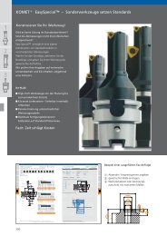
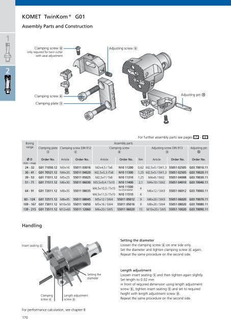
KOMET TwinKom® G01<br />
Assembly Parts and Construction<br />
X D<br />
min - max<br />
Order No. Article Order No. Article Order No. Nm Article Order No. Order No.<br />
24 - 32 G01 71050.12 M3×16 55011 03016 M2×4,5 / Tx6 N10 11200 0,62 M2,5×5 / SW1,3 55051 02505 G03 70010.11<br />
170<br />
Clamping screw �<br />
only required for twin cutter<br />
with axial adjustment<br />
Boring<br />
range<br />
Clamping screw �<br />
Clamping plate �<br />
Adjusting screw �<br />
Adjusting pin �<br />
For further assembly parts see pages 172 - 181.<br />
30 - 41 G01 70521.12 M4×20 55011 04020 M2,5×5,3 /Tx8 N10 11300 1,25 M2,5×5 / SW1,3 55051 02505 G03 70020.11<br />
39 - 53 G01 71011.12 M5×25 55011 05025 M2,5×7 / Tx8 N10 11310 1,25 M4×8 / SW2 55051 04008 G03 70030.11<br />
51 - 71 G01 71511.12 M6×30 55011 06030 M3,5×9,4 / Tx10 N10 11400 2,1 M4×10 / SW2 55051 04010 G03 70040.11<br />
64 - 91 G01 72011.12 M8×35<br />
M4,5×10,5 / Tx15<br />
55011 08035<br />
N10 11500<br />
for D54 60450<br />
4<br />
M6×12 / SW3 55051 06012 G03 70060.11<br />
M4,5×11,5 / Tx15 N10 11510 4<br />
83 - 124 G01 72511.12 M8×45 55011 08045 M5×12 / SW4 55011 05012 9 M6×20 / SW3 55051 06020 G03 70070.11<br />
109 - 167 G01 73011.12 M10×50 55011 10050 M5×16 / SW4 55011 05016 9 M8×20 / SW4 55051 08020 G03 70080.11<br />
139 - 215 G01 73511.12 M12×60 55011 12060 M6×20 / SW5 55011 06020 15 M10×20 / SW5 55051 10020 G03 70090.11<br />
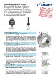
Handling<br />
Insert seating �<br />
Clamping plate<br />
�<br />
Clamping<br />
screw �<br />
Clamping screw DIN 912<br />
�<br />
Length adjustment<br />
screw �<br />
For performance calculation, see chapter 8<br />
Setting the<br />
diameter<br />
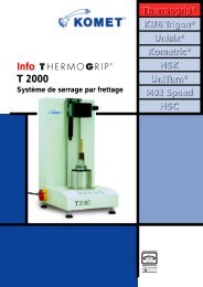
Assembly parts<br />
Clamping screw<br />
�<br />
Adjusting screw DIN 913<br />
�<br />
Adjusting pin<br />
�<br />
Setting the diameter<br />
Loosen the clamping screw � on one side only.<br />
Set the diameter and tighten clamping screw � again.<br />
Repeat the same procedure on the second side.<br />
Length adjustment<br />
Loosen insert seating � and then tighten again slightly.<br />
Set length to 0.02 mm<br />
in front of required dimension using length adjustment<br />
screw �, tighten insert seating � and set to required<br />
height with length adjustment screw �.<br />
Repeat the same procedure on the second side.