944-0140 D20MX Substation Gateway ... - GE Digital Energy
944-0140 D20MX Substation Gateway ... - GE Digital Energy
944-0140 D20MX Substation Gateway ... - GE Digital Energy

You also want an ePaper? Increase the reach of your titles
YUMPU automatically turns print PDFs into web optimized ePapers that Google loves.
CHAPTER 3: CONNECTING TO DEVICES AND NETWORKS<br />
Twisted-pair Ethernet (for 526-3001 only)<br />
NOTE<br />
To connect the <strong>D20MX</strong><br />
to network devices<br />
NOTE<br />
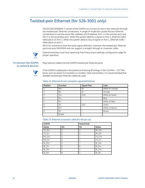
The10/100/1000BASE-T variant of the <strong>D20MX</strong> can connect to one or two networks through<br />
two twisted-pair Ethernet connections. In single-IP mode this causes the two Ethernet<br />
connections to use the same MAC address and IP address. Port 1 is the primary port and<br />
Port 2 is the secondary port. When the system detects a signal on Port 1, Ethernet traffic<br />
takes place on Port 1. When the system detects loss of signal on Port 1, Ethernet traffic<br />
takes place on port 2.<br />
All RJ-45 connectors have the same signal definition. However, the twisted-pair Ethernet<br />
ports are auto MDI/MDIX and can support a straight-through or crossover cable.<br />
External switches must have Spanning Tree Protocol port settings configured to edge for<br />
proper operation.<br />
Plug network cables into the <strong>D20MX</strong> twisted-pair Ethernet ports.<br />
If the <strong>D20MX</strong> is deployed in the presence of strong RF energy in the 110 MHz - 125 MHz<br />
band, such as airport ILS localizers or aviation radio transmitters, it is recommended that<br />
shielded twisted-pair Ethernet cables be used.<br />
Table 12: Ethernet RJ-45 connector signal definitions<br />
Position Function Signal Flow Color<br />
1 RX+ IN White w/ Orange<br />
2 RX- IN Orange<br />
3 TX+ OUT White w/ Green<br />
4 P1+ - Blue<br />
5 P1- - White w/ Blue<br />
6 TX- OUT Green<br />
7 P2+ - White w/ Brown<br />
8 P2- - Brown<br />
Shield - -<br />
Table 13: Ethernet crossover cable (RJ-45) pin out<br />
<strong>D20MX</strong> Switch/Hub<br />
Name Pin Pin Name<br />
TX_D1+ 1 3 RX_D2+<br />
TX_D1- 2 6 RX_D2-<br />
RX_D2+ 3 1 TX_D1+<br />
RX_D2- 4 2 TX_D1-<br />
BI_D3+ 5 7 BI_D4+<br />
BI_D3- 6 8 BI_D4-<br />
BI_D4+ 7 4 BI_D3+<br />
BI_D4- 8 5 BI_D3-<br />
42 <strong>GE</strong>NERAL <strong>D20MX</strong> HARDWARE USER’S MANUAL