944-0140 D20MX Substation Gateway ... - GE Digital Energy
944-0140 D20MX Substation Gateway ... - GE Digital Energy
944-0140 D20MX Substation Gateway ... - GE Digital Energy

You also want an ePaper? Increase the reach of your titles
YUMPU automatically turns print PDFs into web optimized ePapers that Google loves.
To set up a redundant<br />
system<br />
To manually operate<br />
the RS-232 switch<br />
panel<br />
CHAPTER 3: CONNECTING TO DEVICES AND NETWORKS<br />
It is recommended that you install and configure one standalone D20 unit to ensure that<br />
your configuration is valid and that device communications are operating properly. Once<br />
this is done, proceed with the installation of the redundant system.<br />
1. Mount the D20 units in a rack and connect power and ground.<br />
2. Mount the RS-232 switch panel.<br />
3. Plug the connector of watchdog cable A (<strong>GE</strong> part number 977-0160) to serial<br />
connector COM 6 on the first D20 (CCU A).<br />
4. Connect the bare leads of watchdog cable A to TB1 (position 6-8) on the RS-232 switch<br />
panel.<br />
5. Plug the connector of watchdog cable B (<strong>GE</strong> part number 977-0160) to serial<br />
connector COM 6 on the second D20 (CCU B).<br />
6. Connect the bare leads of watchdog cable B to TB1 (position 14-16) on the RS-232<br />
switch panel.<br />
7. Connect the bare leads of both watchdog cables to TB1 on the RS-232 switch panel<br />
and the DB9 serial connector to either P1 or P9.<br />
8. Connect one end of the ping cable to the first D20 and the other end to the second<br />
D20. This ping cable must be connected to the same serial port number on both units.<br />
9. Use standard RS-232 cables (<strong>GE</strong> part number 977-0121) to connect the D20 serial<br />
communication ports to the serial ports on the RS-232 switch panel. P1 through P8 are<br />
connected to the first D20, P9 through P16 are connected to the second D20.<br />
Connections from the switch panel to both D20 units should be made in the same<br />
order. For example, if P1 is connected to port 3 on the first D20, P9 should also be<br />
connected to port 3 on the second D20.<br />
10. Connect field devices to J1 through J8 on the RS-232 switch panel.<br />
RS-232 switch panel operation<br />
The RS2-32 switch panel has two sets of indicator LEDS:<br />
• PWR A/PWR B: When lit, power and communications are received from the connected<br />
units. Normally, both LEDs are lit.<br />
• CCU A/CCU B: Normally, one LED is lit, indicating which unit is active.<br />
The active/standby switch on the front of the RS-232 switch panel is used to:<br />
• Restore a previously failed unit to active status once it has been repaired.<br />
• Manually force a unit to active status so that routine maintenance can be performed<br />
on the other unit.<br />
1. Pull the active/standby switch straight out to release it from the locked position.<br />
2. Switch it up to make unit A active or down to make unit B active.<br />
The CCU A/CCU B LED indicator indicates which unit has been activated.<br />
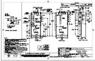
Redundancy wiring diagrams<br />
NOTE<br />
Figure 22 illustrates how to wire the <strong>D20MX</strong> units and RS-232 switch panels to enable<br />
system redundancy:<br />
The <strong>D20MX</strong> watchdog (control) port, heartbeat (ping) port, and serial port assignments are<br />
software configurable. Refer to the D2x Configuration Guides.<br />
50 <strong>GE</strong>NERAL <strong>D20MX</strong> HARDWARE USER’S MANUAL