944-0140 D20MX Substation Gateway ... - GE Digital Energy
944-0140 D20MX Substation Gateway ... - GE Digital Energy
944-0140 D20MX Substation Gateway ... - GE Digital Energy

You also want an ePaper? Increase the reach of your titles
YUMPU automatically turns print PDFs into web optimized ePapers that Google loves.
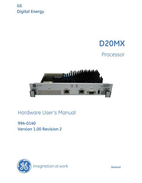
<strong>GE</strong><br />
<strong>Digital</strong> <strong>Energy</strong><br />
Hardware User’s Manual<br />
994-<strong>0140</strong><br />
Version 1.00 Revision 2<br />
<strong>D20MX</strong><br />
Processor<br />
General
Copyright Notice<br />
© 2012, General Electric Company. All rights reserved.<br />
<strong>GE</strong> <strong>Digital</strong> <strong>Energy</strong><br />
The information contained in this online publication is the exclusive property of General Electric Company,<br />
except as otherwise indicated. You may view, copy and print documents and graphics incorporated in this online<br />
publication (the “Documents”) subject to the following: (1) the Documents may be used solely for personal, informational,<br />
non-commercial purposes; (2) the Documents may not be modified or altered in any way; and (3) General<br />
Electric Company withholds permission for making the Documents or any portion thereof accessible via the<br />
internet. Except as expressly provided herein, you may not use, copy, print, display, reproduce, publish, license,<br />
post, transmit or distribute the Documents in whole or in part without the prior written permission of General<br />
Electric Company.<br />
The information contained in this online publication is proprietary and subject to change without notice. The<br />
software described in this online publication is supplied under license and may be used or copied only in accordance<br />
with the terms of such license.<br />
Trademark Notices<br />
<strong>GE</strong> and are trademarks and service marks of General Electric Company.<br />
* Trademarks of General Electric Company.<br />
ERNI is a registered trademark of ERNI Elektroapparate GMBH. Hyperterminal is a registered trademark of Hilgraeve,<br />
Tera Term is a registered trademark of T. Teranishi, Incorporated. IEC is a registered trademark of Commission<br />
Electrotechnique Internationale. IEEE is a registered trademark of the Institute of Electrical and<br />
Electronics Engineers, Inc. Internet Explorer, Microsoft, and Windows are registered trademarks of Microsoft Corporation.<br />
JAVA and J2SE are registered trademarks of Sun Microsystems, Inc. Maxell is a registered trademark of<br />
Hitachi Maxell, Ltd. MiniSQL is a trademark of Hughes Technologies. Modbus is a registered trademark of Schneider<br />
Automation Inc. Panduit is a registered trademark of Panduit Corp. Saft is a registered trademark of SAFT<br />
société anonyme. SEL is a registered trademark of Schweitzer Engineering Laboratories, Inc. Silicon Systems is a<br />
registered trademark of Silicon Systems, Inc. Sonnenschein is a registered trademark of Deutsche Exide GMBH.<br />
Tadiran is a registered trademark of Tadiran Israel Electronics Industries Ltd. Toshiba is a registered trademark of<br />
Kabushiki Kaisha Toshiba, doing business as Toshiba Corporation. VESA is registered trademark of Video Electronics<br />
Standards Association Corporation.<br />
Other company or product names mentioned in this document may be trademarks or registered trademarks of<br />
their respective companies.<br />
This printed manual is recyclable.�<br />
Please return for recycling where facilities exist.
ABOUT THIS<br />
DOCUMENT<br />
<strong>D20MX</strong> Processor<br />
Table of contents<br />
Purpose ............................................................................................................................7<br />
Intended audience ........................................................................................................7<br />
Additional documentation ...........................................................................................7<br />
How to use this manual ................................................................................................8<br />
Document conventions .................................................................................................8<br />
Safety words and definitions........................................................................................9<br />
PRODUCT SUPPORT Search technical support ...........................................................................................11<br />
Contact customer support ........................................................................................11<br />
Product returns.............................................................................................................12<br />
Upgrade your <strong>D20MX</strong> processor firmware ..............................................................12<br />
BEFORE YOU START Safety precautions ......................................................................................................13<br />
Warning symbols .........................................................................................................................................14<br />
Regulatory compliance information ........................................................................14<br />
CE Mark compliance ....................................................................................................................................14<br />
Export control classification number...................................................................................................15<br />
Product overview..........................................................................................................15<br />
Product design................................................................................................................................................15<br />
<strong>D20MX</strong> Processor .........................................................................................................................................15<br />
Security ..............................................................................................................................................................16<br />
<strong>D20MX</strong> applications ....................................................................................................................................16<br />
Firmware/FPGA versions ...........................................................................................................................17<br />
D20 chassis ......................................................................................................................................................18<br />
Power supply...................................................................................................................................................20<br />
Modems .............................................................................................................................................................21<br />
Peripherals........................................................................................................................................................22<br />
Ordering guide..............................................................................................................23<br />
<strong>D20MX</strong> upgrade kits.....................................................................................................24<br />
Product specifications ................................................................................................25<br />
Storage recommendations.........................................................................................27<br />
Storage conditions ......................................................................................................................................27<br />
<strong>D20MX</strong> HARDWARE USER’S MANUAL <strong>GE</strong>NERAL 3
INSTALLING THE<br />
<strong>D20MX</strong><br />
CONNECTING TO<br />
DEVICES AND<br />
NETWORKS<br />
POWERING-UP AND<br />
TESTING<br />
CONFIGURING THE<br />
SOFTWARE<br />
TABLE OF CONTENTS<br />
D20 chassis layouts .....................................................................................................29<br />
Installation steps..........................................................................................................31<br />
Retrofitting the <strong>D20MX</strong> in an existing D20 ..............................................................33<br />
Required tools and materials.....................................................................................35<br />
Grounding the <strong>D20MX</strong> .................................................................................................36<br />
Unpacking the <strong>D20MX</strong> .................................................................................................36<br />
Package contents..........................................................................................................................................36<br />
Connecting the power supply ....................................................................................37<br />
Cabling overview ..........................................................................................................39<br />
<strong>D20MX</strong> front panel connectors ...............................................................................................................39<br />
General cabling requirements.................................................................................................................40<br />
Serial ...............................................................................................................................41<br />
D.20 Link.........................................................................................................................41<br />
Twisted-pair Ethernet (for 526-3001 only)...............................................................42<br />
Fiber optic Ethernet (for 526-3003 and 526-3005LF only).....................................43<br />
LAN redundancy ...........................................................................................................44<br />
IP addresses ..................................................................................................................44<br />
RS-232.............................................................................................................................47<br />
D20 system redundancy .............................................................................................47<br />
Failover sequence..........................................................................................................................................49<br />
Required components .................................................................................................................................49<br />
RS-232 switch panel operation ...............................................................................................................50<br />
Redundancy wiring diagrams..................................................................................................................50<br />
Required for testing .....................................................................................................53<br />
Accessing WESMAINT II+ using a terminal.........................................................................................54<br />
Terminal Emulation.......................................................................................................................................54<br />
SHELL...................................................................................................................................................................54<br />
Power up and test steps..............................................................................................54<br />
Set up a PC to act as a WESMAINTII+ terminal.......................................................55<br />
Power up the <strong>D20MX</strong>....................................................................................................55<br />
Automatic on-line start-up test.................................................................................55<br />
Code and configuration files ....................................................................................................................56<br />
Further testing.................................................................................................................................................56<br />
Test for redundancy.....................................................................................................56<br />
Check that fail-over is functioning correctly...........................................................57<br />
Check that switch-over is functioning correctly ....................................................57<br />
Verify either hardware or software switch-over ....................................................58<br />
Introduction to the <strong>D20MX</strong> software ........................................................................59<br />
<strong>D20MX</strong> user accounts .................................................................................................59<br />
Default user ......................................................................................................................................................60<br />
Recovery mode users ..................................................................................................................................60<br />
Download image files to the <strong>D20MX</strong>.........................................................................61<br />
When to download........................................................................................................................................61<br />
Prerequisites for image download.........................................................................................................61<br />
Download software over a serial connection...................................................................................62<br />
Download software over a network connection ............................................................................64<br />
4 <strong>GE</strong>NERAL <strong>D20MX</strong> HARDWARE USER’S MANUAL
TABLE OF CONTENTS<br />
SGConfig firmware options ........................................................................................65<br />
Update to the SAN0001 firmware option.................................................................66<br />
Transfer D20/D200 configurations to the <strong>D20MX</strong> .................................................68<br />
Transferring a D20 configuration to the <strong>D20MX</strong> ............................................................................69<br />
Transferring a D200 configuration to the <strong>D20MX</strong>..........................................................................74<br />
Updating D20/D200 configurations to use the <strong>D20MX</strong> firmware definition with<br />
ConfigPro.............................................................................................................75<br />
Updating a D20 configuration to use the <strong>D20MX</strong> firmware definition with ConfigPro 76<br />
Updating a D200 configuration to use the <strong>D20MX</strong> firmware definition with ConfigPro ..<br />
78<br />
USING THE <strong>D20MX</strong> Front panel LEDs ..........................................................................................................81<br />
Operational status LEDs.............................................................................................................................81<br />
LAN port status LEDs ...................................................................................................................................82<br />
Fiber optic port status LEDs .....................................................................................................................82<br />
SERVICING THE<br />
<strong>D20MX</strong><br />
DEFAULT ROLE-<br />
BASED ACCESS<br />
CONTROL MODEL<br />
STANDARDS &<br />
PROTECTION<br />
Performing periodic inspection ................................................................................83<br />
Removing the <strong>D20MX</strong> processor module ................................................................83<br />
Configured roles in the <strong>D20MX</strong> ..................................................................................85<br />
Compliance standards ................................................................................................91<br />
LIST OF ACRONYMS Acronym Definitions ....................................................................................................95<br />
Modification Record .................................................................................................................................. 103<br />
<strong>D20MX</strong> HARDWARE USER’S MANUAL <strong>GE</strong>NERAL 5
TABLE OF CONTENTS<br />
6 <strong>GE</strong>NERAL <strong>D20MX</strong> HARDWARE USER’S MANUAL
<strong>D20MX</strong> Processor<br />
About this Document<br />
Purpose<br />
About this Document<br />
This manual provides information about installing, setting up, using and maintaining your<br />
<strong>D20MX</strong> TM Processor. This manual does not provide any procedures for configuring the<br />
software of the <strong>D20MX</strong>.<br />
Intended audience<br />
This manual is intended for use by field technicians and maintenance personnel who are<br />
responsible for the installation, wiring and maintenance of SCADA equipment. This manual<br />
assumes that the user is experienced in:<br />
• Electrical utility applications<br />
• Electrical wiring and safety procedures<br />
• Related other manufacturers’ products, such as protective relays and<br />
communications equipment<br />
Additional documentation<br />
For further information about the <strong>D20MX</strong>, refer to the following documents.<br />
• SGConfig Online Help<br />
• D20/D200 Installation and Operation Guide, 994-0078<br />
• Application Configuration Guides and User Guides (available on the <strong>D20MX</strong><br />
Documentation CD)<br />
<strong>D20MX</strong> HARDWARE USER’S MANUAL <strong>GE</strong>NERAL 7
How to use this manual<br />
ABOUT THIS DOCUMENT<br />
This manual describes how to install the <strong>D20MX</strong> and get it up and running for the first time.<br />
Procedures are provided for all component options available for the <strong>D20MX</strong>. The<br />
components included in your <strong>D20MX</strong> depend on what was ordered for your substation<br />
application.<br />
The software-related procedures in this manual are based on using a computer running<br />
Windows ® XP. Some steps and dialog boxes may vary slightly if you are using another<br />
version of Windows.<br />
Document conventions<br />
The following typographic conventions are used throughout this manual:<br />
Bold face is used for:<br />
• Names of software program menus, editors, and dialog boxes; also for the names of<br />
menu commands, keyboard keys, icons and desktop shortcuts, and buttons and fields<br />
in editors and dialog boxes<br />
• Names of hardware components<br />
• User input that must be typed exactly<br />
Italic face is used for:<br />
• Emphasis<br />
• Cross-references to sections, figures and tables within this manual and for titles of<br />
other documents<br />
• File and directory names; examples of directory paths are generally given in the<br />
Windows format<br />
• Placeholders for user input that is specific to the user. May also include angle brackets<br />
around the placeholder if the placeholder is already in italic text. For example,<br />
c:\\product.def<br />
• References to a parameter or field value shown<br />
8 <strong>GE</strong>NERAL <strong>D20MX</strong> HARDWARE USER’S MANUAL
ABOUT THIS DOCUMENT<br />
Safety words and definitions<br />
Before attempting to install or use the device, review all safety indicators in this document<br />
to help prevent injury, equipment damage or downtime.<br />
The following safety and equipment symbols are used in this document:<br />
Indicates a hazardous situation which, if not avoided, will result in death or serious<br />
injury.<br />
Indicates a hazardous situation which, if not avoided, could result in death or serious<br />
injury.<br />
Indicates a hazardous situation which, if not avoided, could result in minor or<br />
moderate injury.<br />
Indicates practices that are not related to personal injury.<br />
<strong>D20MX</strong> HARDWARE USER’S MANUAL <strong>GE</strong>NERAL 9
ABOUT THIS DOCUMENT<br />
10 <strong>GE</strong>NERAL <strong>D20MX</strong> HARDWARE USER’S MANUAL
<strong>D20MX</strong> Processor<br />
Product Support<br />
Product Support<br />
If you need help with any aspect of your <strong>GE</strong> <strong>Digital</strong> <strong>Energy</strong> product, you have a few options.<br />
Search technical support<br />
The <strong>GE</strong> <strong>Digital</strong> <strong>Energy</strong> Web site provides fast access to technical information, such as<br />
manuals, release notes and knowledge base topics at:<br />
http://www.gedigitalenergy.com<br />
Contact customer support<br />
The <strong>GE</strong> <strong>Digital</strong> <strong>Energy</strong> Customer Service Center is open 24 hours a day, seven days a week<br />
for you to talk directly to a <strong>GE</strong> representative.<br />
In the U.S. and Canada, call toll-free: 1 800-547-8629<br />
International customers, please call: + 1 905-927-7070<br />
Or e-mail to ge4service@ge.com<br />
Have the following information ready to give to Customer Service:<br />
• Ship to address (the address that the product is to be returned to)<br />
• Bill to address (the address that the invoice is to be sent to)<br />
• Contact name<br />
• Contact phone number<br />
• Contact fax number<br />
• Contact e-mail address<br />
• Product number / serial number<br />
• Description of problem<br />
The Customer Service centre will provide you with a case number for your reference.<br />
<strong>D20MX</strong> HARDWARE USER’S MANUAL <strong>GE</strong>NERAL 11
Product returns<br />
NOTE<br />
PRODUCT SUPPORT<br />
A Return Merchandise Authorization (RMA) number must accompany all equipment being<br />
returned for repair, servicing, or for any other reason. Before you return a product, please<br />
contact <strong>GE</strong> <strong>Digital</strong> <strong>Energy</strong> to obtain an RMA number and instructions for return shipments.<br />
You will be sent the RMA number and RMA documents via fax or e-mail. Once you receive<br />
the RMA documents, attach them to the outside of the shipping package and ship to <strong>GE</strong>.<br />
Product returns will not be accepted unless accompanied by the Return Merchandise<br />
Authorization number.<br />
Upgrade your <strong>D20MX</strong> processor firmware<br />
The firmware of your <strong>D20MX</strong> Processor can be upgraded to provide the latest functionality<br />
and improvements. Visit the customer support web site at http://<br />
www.gedigitalenergy.com to download the upgrade software and instruction guide.<br />
12 <strong>GE</strong>NERAL <strong>D20MX</strong> HARDWARE USER’S MANUAL
<strong>D20MX</strong> Processor<br />
Chapter 1: Before You Start<br />
Before You Start<br />
The new <strong>D20MX</strong> processor card is a pin-for-pin compatible replacement for all generations<br />
of the D20 SBC, providing the latest revisions of common D20 applications and<br />
performance enhancements to support NERC-compliant Cyber security.<br />
Before you begin installing and using the <strong>D20MX</strong>, review the information in this chapter,<br />
including the following topics:<br />
• Safety precautions<br />
• Regulatory compliance information<br />
• Product overview<br />
• Product specifications<br />
• Storage recommendations<br />
Read and thoroughly understand this manual before installing and operating the unit.<br />
Save these instructions for later use and reference.<br />
WARNING! Failure to observe the instructions in this manual may result in serious<br />
injury or death.<br />
Safety precautions<br />
Follow all safety precautions and instructions in this manual.<br />
Only qualified personnel should work on the <strong>D20MX</strong>. Maintenance personnel should be<br />
familiar with the technology and the hazards associated with electrical equipment.<br />
• Never work alone.<br />
• Before performing visual inspections, tests, or maintenance on this equipment, isolate<br />
or disconnect all hazardous live circuits and sources of electric power. Assume that all<br />
circuits are live until they have been completely de-energized, tested, and tagged. Pay<br />
particular attention to the design of the power system. Consider all sources of power,<br />
including the possibility of back feed.<br />
• Turn off all power supplying the equipment in which the <strong>D20MX</strong> is to be installed<br />
before installing and wiring the <strong>D20MX</strong>.<br />
• Operate only from the power source specified on the installed power supply module.<br />
• Beware of potential hazards and wear personal protective equipment.<br />
<strong>D20MX</strong> HARDWARE USER’S MANUAL <strong>GE</strong>NERAL 13
CHAPTER 1: BEFORE YOU START<br />
• The successful operation of this equipment depends upon proper handling,<br />
installation, and operation. Neglecting fundamental installation requirements may<br />
lead to personal injury as well as damage to electrical equipment or other property.<br />
• All AC voltage terminals are protected from accidental contact by a mechanical safety<br />
shield.<br />
• All electronic components within the <strong>D20MX</strong> are susceptible to damage from<br />
electrostatic discharge. To prevent damage when handling this product use approved<br />
static control procedures.<br />
• Hazardous voltages can cause shock, burns or death. To prevent exposure to<br />
hazardous voltages, disconnect and lock out all power sources before servicing and<br />
removing components.<br />
• If the <strong>D20MX</strong> is used in a manner not specified in this manual, the protection provided<br />
by the equipment may be impaired.<br />
• Changes or modifications made to the unit not authorized by <strong>GE</strong> <strong>Digital</strong> <strong>Energy</strong> could<br />
void the warranty.<br />
Warning symbols<br />
Table 1 explains the meaning of warning symbols that may appear on the <strong>D20MX</strong>.<br />
Table 1: Warning symbols<br />
Symbol Description<br />
!<br />
Regulatory compliance information<br />
CE Mark compliance<br />
The relevant circuit is direct current.<br />
The relevant circuit is alternating current.<br />
Caution: Refer to the documentation for important operation and<br />
maintenance instructions. Failure to take or avoid specified actions<br />
could result in loss of data or physical damage.<br />
Warning: Dangerous voltage constituting risk of electric shock is<br />
present within the unit. Failure to take or avoid specified actions<br />
could result in physical harm to the user.<br />
Earth/Ground Terminal<br />
Protective Ground Terminal<br />
Caution: Hot Surface<br />
The <strong>D20MX</strong> is rated as CISPR 11 Group 1 Class “A” equipment.<br />
To meet essential safety requirements of the LV Directive 2006/95/EC, the D20 chassis<br />
must be installed in a secondary cabinet if an operating voltage on any of the terminals is<br />
equal to or higher than 50 VAC or 75 VDC. Proper wiring practices and applicable local<br />
safety standards defining protection against electrical shock must be followed at all times.<br />
14 <strong>GE</strong>NERAL <strong>D20MX</strong> HARDWARE USER’S MANUAL
CHAPTER 1: BEFORE YOU START<br />
NOTE<br />
To provide higher EMC immunity and maintain CE Mark compliance, the serial cables used<br />
for permanent RS-232 and RS-485 connections must comply with the following<br />
requirements:<br />
• Cables must be shielded<br />
• D type connector covers must provide EMC shielding (e.g., metallized plastic or die<br />
cast metal covers) for permanently connected RS-232 cables<br />
Class “A” equipment is intended for use in an industrial environment. The equipment<br />
generates, uses and can radiate radio frequency energy and, if not installed and used in<br />
accordance with these instructions, may cause interference to other devices in the vicinity.<br />
If this equipment does cause interference with other devices, which can be determined by<br />
turning the equipment off and on, the user is encouraged to try to correct the interference<br />
by one or more of the following measures:<br />
• Reorient or relocate the receiving device<br />
• Increase the separation between the equipment<br />
• Connect the equipment into an outlet on a circuit different from that to which the<br />
other device(s) is connected<br />
• Consult the manufacturer or field service technician for help<br />
Export control classification number<br />
The Export Control Classification Number (ECCN) of the <strong>D20MX</strong> Processor is 4A994.<br />
Product overview<br />
Product design<br />
The D20 is a standalone remote terminal unit (RTU). It consists of a <strong>D20MX</strong> processor<br />
board, power supply, optional termination panels, and optional communications<br />
equipment in a 3U tall, 19-inch wide chassis. These components, combined with software<br />
applications running on the <strong>D20MX</strong>, form the D20 RTU System.<br />
The D20 acts as a data concentrator and central processor. Field data gathered through<br />
the peripheral modules and external Intelligent Electronic Devices (IEDs) are stored in the<br />
system database and can be accessed by the application programs loaded on the D20.<br />
The D20 design has horizontally mounted processor boards, with multiple boards in some<br />
versions.<br />
Peripheral I/O boards operate independently of the main chassis and <strong>D20MX</strong> processor<br />
board. This means that you can use a D20 without direct connection to peripheral boards<br />
so that it acts as a master data concentrator to other RTUs. You can also hot-swap the<br />
peripherals without powering down the main processor. For information on peripheral<br />
modules, see the D20/D200 Installation and Operations Guide (part number 994-0078); see<br />
section: Connections and Configuration.<br />
<strong>D20MX</strong> Processor<br />
The <strong>D20MX</strong> is a single board computer built around a 667 MHz embedded PowerQUICC II<br />
Pro processor. The <strong>D20MX</strong> permits the D20 to be NERC CIPS compliant and introduces<br />
compliance to IEC standards; refer to Appendix A, Standards & Protection for the complete<br />
listing.<br />
<strong>D20MX</strong> HARDWARE USER’S MANUAL <strong>GE</strong>NERAL 15
Security<br />
CHAPTER 1: BEFORE YOU START<br />
The <strong>D20MX</strong> can be retrofitted into either a D20 3U single-node VME chassis or D20 3U non-<br />
VME chassis. In a single-node VME chassis, this one processor module replaces the<br />
previous D20 M, M++, ME, and MEII CPU cards.<br />
Due to aging printed circuit board assembly and mechanical constraints, only certain<br />
chassis from 2002 and onward can be used with a <strong>D20MX</strong>. This comprises the following<br />
chassis:<br />
• D20 VME chassis 500-0280 Release 08 or higher,<br />
• D20 Non-VME chassis 500-0305 Release 18 or higher<br />
A solid partition between the Main processor bay and accessory bay prevents access to<br />
the harness from the fiber card to <strong>D20MX</strong> card (only applicable to the 526-3005LF fiber<br />
card version).<br />
The <strong>D20MX</strong> provides many new security improvements over its predecessors. To take<br />
advantage of these improvements, refer to the WESMAINT II+ for the <strong>D20MX</strong> Configuration<br />
Guide (B014-1NCG) for details on configuration of these security features of the <strong>D20MX</strong>.<br />
<strong>D20MX</strong> applications<br />
Table 2 lists the automation applications used on the <strong>D20MX</strong>. Notice that the application<br />
versions are different in the SAN0001 and SAN0002 columns (for example, see application<br />
ID B021N).<br />
Table 2: <strong>D20MX</strong> applications<br />
Application<br />
ID<br />
Application Name Description Version<br />
A026-1 Communication<br />
Watchdog<br />
Reports on the state of communications<br />
between the RTU and a remote device.<br />
SAN0001 SAN0002<br />
321 321<br />
A027 SOE Logger DTA SOE Logger DTA configuration. 832 832<br />
A030 Accumulator Freeze Detects system status point changes<br />
and system accumulator point freezes.<br />
300 300<br />
A033-5 TEJAS V DPA TEJAS V DPA configuration. 211 211<br />
A035 Analog Reference Analog reference check DTA. 211 211<br />
A036N ProLogic Executor ProLogic Executor DTA 421 421<br />
A059 Modbus DCA Modbus Data Collection Application 911 911<br />
A068 Modbus DPA Modbus DPA Configuration 311 311<br />
A088-0 SM DTA <strong>Substation</strong> Maintenance DTA<br />
configuration<br />
203 203<br />
A113 PSR DCA Programmable Synchrocheck Relay (PSR) 301<br />
DCA configuration<br />
301<br />
A118 Failover DTA Failover data-translation application<br />
(DTA) configuration.<br />
103 103<br />
A123-0 NGC General DTA NGC General DTA configuration. 111 111<br />
A184-0 General Alarm DTA Takes several alarms and groups them<br />
together under one General Alarm.<br />
120 120<br />
B003 D.20 Peripheral Link D.20 peripheral interface. 751 751<br />
B008-1 System Point Maintains the database of system points 310 310<br />
Database<br />
in the RTU.<br />
B009 Mailbox DTA Mailbox system point conversion<br />
application.<br />
400 310<br />
B012N IRIG-B IRIG-B universal time coordination 201 201<br />
16 <strong>GE</strong>NERAL <strong>D20MX</strong> HARDWARE USER’S MANUAL
CHAPTER 1: BEFORE YOU START<br />
Application<br />
ID<br />
B013 DNP V3.00 Data Link Distributed network protocol (DNP) V3.00<br />
data link configuration.<br />
560 560<br />
B014-1N WESMAINT II+ RTU maintenance facility. 600 600<br />
B015 Bridgeman Bridgeman configuration. 530 530<br />
B021N DNP V3.00 DPA Distributed Network Protocol (DNP) V3.00<br />
DPA Configuration.<br />
988 912<br />
B023 DNP V3.00 DCA Distributed Network Protocol (DNP) V3.00<br />
DCA Configuration.<br />
754 754<br />
B034 Redundant Monitor Redundant monitor configuration. 203 203<br />
B045-0 D20AC WESMAINT II+<br />
Display Screens<br />
Provides D20AC WESMAINT II+ displays. 101 101<br />
B052-0N DNP Internet Data<br />
Link<br />
DNP V3.00 Data Link over Internet. 351 351<br />
B071-0 WESMAINT File<br />
Upload<br />
B100-0 Internet Protocol<br />
Stack<br />
B152-0N IP Redundancy<br />
Monitor<br />
B153-0 Password<br />
Synchronization<br />
Manager<br />
Firmware/FPGA versions<br />
Application Name Description Version<br />
SAN0001 SAN0002<br />
Table 3 lists the firmware, FPGA and other version information.<br />
Table 3: Firmware/FPGA versions information<br />
Uploads files via the WESMAINT port as S<br />
records or using ZMODEM.<br />
200 200<br />
Internet Protocol Stack Configuration 141 141<br />
Provides health and active pseudo DI<br />
points for LAN Ports.<br />
100 100<br />
Synchronizes passwords to Standby CCU 100 100<br />
S032 D20S Peripheral<br />
Board (supports B003)<br />
D20S Peripheral Board Code 303 303<br />
S033 D20A Peripheral<br />
Board (supports B003)<br />
D20A Peripheral Board Code 301 301<br />
S034 D20K Peripheral D20K Peripheral Board Code<br />
Board (supports B003)<br />
306 306<br />
S035 D20C Peripheral<br />
Board (supports B003)<br />
D20C Peripheral Board Code 307 307<br />
S055-0 D20AC Peripheral<br />
Board (supports B003)<br />
D20AC Peripheral Board Code 108 108<br />
Component Version ID Type ID Date How to Find<br />
JMON 1.0.624-<br />
2209<br />
N/A N/A Wed Aug 15<br />
2012 09:44AM<br />
“D20 Version” shown<br />
during cold boot<br />
sequence:.<br />
Board N/A Board <strong>D20MX</strong> N/A “Board ID” shown via<br />
SHELL command: si<br />
Local Bus<br />
FPGA<br />
3.02 N/A N/A N/A “FPGA version” shown via<br />
SHELL command: si<br />
NVRAM FPGA 21 File 15 N/A “NVRAM Rev” shown via<br />
SHELL command: si<br />
VxWorks O/S<br />
and BSP<br />
v1.0/0 Build 0aeaed3881ca956f Oct 7 2012,<br />
16:13:38<br />
Application v1.00 Build 673e5b3f1f38f219 Oct 8 2012 -<br />
16:22:09<br />
SHELL command: ver<br />
SHELL command: ver<br />
<strong>D20MX</strong> HARDWARE USER’S MANUAL <strong>GE</strong>NERAL 17
D20 chassis<br />
CHAPTER 1: BEFORE YOU START<br />
For a detailed description of the D20 chassis options and components, refer to<br />
Familiarization chapter in the D20/D200 Installation and Operation Guide, 994-0078. The<br />
<strong>D20MX</strong> supports the two versions of the D20 chassis listed in Table 4.<br />
Table 4: Types of D20 chassis<br />
Type <strong>GE</strong> part number Description<br />
D20 non-VME�<br />
1 slot horizontal<br />
D20 VME�<br />
5 slot horizontal<br />
500-0305 Chassis with backplane, external power connections, and<br />
7 serial I/O ports<br />
500-0280 Chassis with 5 card VME backplane<br />
D20 non-VME The D20 non-VME single-slot chassis consists of the following:<br />
• <strong>D20MX</strong> processor board<br />
• Modem slots<br />
• Power supply with switch and fuses; see Figure 1.<br />
Figure 1: D20 non-VME chassis - power supply switch and fuses<br />
Power Supply Switch<br />
Power Supply Fuses<br />
D20 non-VME Chassis<br />
This chassis contains the WESTERM D20M+ SS termination panel, which is attached<br />
directly to the back of the assembly; see Figure 2.<br />
18 <strong>GE</strong>NERAL <strong>D20MX</strong> HARDWARE USER’S MANUAL
CHAPTER 1: BEFORE YOU START<br />
Figure 2: D20 non-VME backplane<br />
Power Supply<br />
Connector Block<br />
D20 Non-VME Chassis<br />
D20 VME The D20 VME-compatible chassis (see Figure 3) can support one <strong>D20MX</strong> main board. When<br />
using the <strong>D20MX</strong> in a VME chassis, the 0 V ground wire must be used.<br />
Figure 3: D20 VME chassis - power supply switch and fuses<br />
Power Supply Switch<br />
Power Supply Fuses<br />
WESTERM D20M+<br />
SS Termination Panel<br />
D20 VME Chassis<br />
This chassis (see Figure 4) contains the WESTERM D20M+ termination panel that is<br />
mounted separately on the D20 chassis. The VME chassis kit includes a VME bus<br />
backplane, called the WESTERM D20VME. The VME bus backplane connects to the<br />
termination panel using a ribbon cable from Slot 1 on the bus backplane.<br />
<strong>D20MX</strong> HARDWARE USER’S MANUAL <strong>GE</strong>NERAL 19
Power supply<br />
CHAPTER 1: BEFORE YOU START<br />
Figure 4: D20 VME chassis - VME bus backplane and D20M+ termination panel<br />
WESTERM D20VME -<br />
VME Bus Backplane<br />
D20 VME Chassis<br />
The chassis-mounted power supply modules are switch-mode converters that provide<br />
output power for the <strong>D20MX</strong> processor board, VME cards, modems and D20 Peripheral I/O<br />
modules, as required. A redundant power supply can be installed to provide fail-over<br />
protection to ensure continuous power to the D20.<br />
If you have an extended system with more than five peripherals, the chassis-mounted D20<br />
power supply is not adequate. In this case, you need to install an external power supply.<br />
Table 5 lists the standard power supplies that are available. Other power supplies are<br />
available for specific requirements. Contact <strong>GE</strong> <strong>Digital</strong> <strong>Energy</strong> for details.<br />
Table 5: Available power supplies<br />
WESTERM D20M+<br />
Termination Panel<br />
<strong>GE</strong> part number Input Output<br />
580-2004 20 to 60 V DC +5 V, 7 A; +12 V, 2 A; -12 V, 1 A; 24 V DC, 3 A<br />
580-2005 20 to 60 V DC +5 V, 7 A; +12 V, 2 A; -12 V, 1 A; 48 V DC, 1.5 A<br />
580-2006 100 to 300 V DC or 85 to 264 V AC +5 V, 7 A; +12 V, 2 A; -12 V, 1 A; 24 V DC, 3 A<br />
580-2007 100 to 300 V DC or 85 to 264 V AC +5 V, 7 A; +12 V, 2 A; -12 V, 1 A; 48 V DC, 1.5 A<br />
Ensure your D20 power input is externally protected for over-current; otherwise damage to<br />
the <strong>D20MX</strong> may occur. The required fuse rating depends on the power consumption of<br />
your system.<br />
The D20 available power supplies, listed in Table 5 are equipped with two field replaceable<br />
fuses.; see Figure 5.<br />
20 <strong>GE</strong>NERAL <strong>D20MX</strong> HARDWARE USER’S MANUAL
CHAPTER 1: BEFORE YOU START<br />
Modems<br />
Figure 5: D20 - Location of field-replaceable fuses<br />
Field-replaceable fuses for the standard chassis-mounted Power Supplies are listed in<br />
Table 6. These are the standard factory-installed fuses, unless otherwise specified. Always<br />
replace with the same type and values of fuse.<br />
Table 6: Field-replaceable fuses<br />
Field-replaceable<br />
fuses<br />
Power Supply Fuse Fuse Function Replacement Fuse<br />
(¼inch by 1 ¼ inch Time Delay)<br />
580 - 2004 F1 +DC Input 12 A / 250 V<br />
F2 -DC Input 12 A / 250 V<br />
580 - 2005 F1 +DC Input 12 A / 250 V<br />
F2 -DC Input 12 A / 250 V<br />
580 - 2006 F1 Line/+DC Input 4 A / 250 V<br />
F2 Neutral/-DC Input 4 A / 250 V<br />
580 - 2007 F1 Line/+DC Input 4 A / 250 V<br />
F2 Neutral/-DC Input 4 A / 250 V<br />
Two D20 modems (can be purchased separately) for communications to a host computer<br />
or to other IEDs:<br />
• WESDAC 202/V.23 is a 1200-baud Bell 202 or CCITT V.23 standard modem designed<br />
for 300 to 1200 baud asynchronous operation on unconditioned lines and supports<br />
the majority of SCADA/EMS applications. It is available in a 19 inch rack mount or 3U<br />
vertical mount configuration in the D20 chassis.<br />
• WESDAC 212/V.23 is a 1200-baud Bell 212 standard modem, (auto answer only), used<br />
for dial-up access to the D20. This modem is available for mounting only as a 3U<br />
vertical mount.<br />
Third-party modems can be used to meet specific requirements. These modems are<br />
connected to the D20 via standard RS-232 connections. Contact <strong>GE</strong> <strong>Digital</strong> <strong>Energy</strong> for<br />
more information on options.<br />
<strong>D20MX</strong> HARDWARE USER’S MANUAL <strong>GE</strong>NERAL 21
Peripherals<br />
CHAPTER 1: BEFORE YOU START<br />
Peripheral I/O modules are intelligent modules containing an on-board microprocessor.<br />
They are configured as slaves to the <strong>D20MX</strong> processor board. In this way, specific I/O<br />
processing is distributed throughout the RTU to the appropriate I/O module.<br />
There are five types of I/O peripherals:<br />
• D20A analog input<br />
• D20S digital inputs<br />
• D20K digital output<br />
• D20C combination input/output<br />
• D20AC alternating current analog input<br />
Optional high-voltage peripherals are also available.<br />
22 <strong>GE</strong>NERAL <strong>D20MX</strong> HARDWARE USER’S MANUAL
CHAPTER 1: BEFORE YOU START<br />
Ordering guide<br />
The latest <strong>D20MX</strong> Processor ordering guide is available on the <strong>GE</strong> <strong>Digital</strong> <strong>Energy</strong> website:<br />
http://www.gedigitalenergy.com/multilin/energy/catalog/<strong>D20MX</strong>.htm<br />
You can select the required options from the available Product Option items. The Order<br />
Code automatically updates as each option is selected.<br />
The Order Codes are listed in Table 7.<br />
Table 7: <strong>D20MX</strong> order codes<br />
Order Code Item<br />
<strong>D20MX</strong> CPU Options<br />
<strong>D20MX</strong> -C X X P -M M M -P F<br />
(A) - <strong>D20MX</strong> non-VME, dual 10/100/1000BASE-TX Ethernet<br />
Ports (front access)<br />
A<br />
(C) - <strong>D20MX</strong> non-VME dual 100BASE-FX Ethernet Ports<br />
(front access)<br />
C<br />
(E) - <strong>D20MX</strong> non-VME, dual 10/100/1000BASE-TX (front<br />
access), conformal coated<br />
E<br />
(F) - <strong>D20MX</strong> non-VME, dual 100BASE-FX Ethernet Ports<br />
(front access), conformal coated<br />
F<br />
(G) - <strong>D20MX</strong> non-VME, dual 100BASE-FX Ethernet Ports<br />
(rear access)<br />
G<br />
(H) - <strong>D20MX</strong> non-VME, dual 100BASE-FX Ethernet Ports<br />
(rear access), conformal coated<br />
<strong>D20MX</strong> Power Supply<br />
H<br />
(U) - Not required U<br />
(A) - D20 Power Supply, 20-60VDC Input, 24V ISO Output A<br />
(B) - D20 Power Supply, 20-60VDC Input, 48V ISO Output B<br />
(C) - D20 Power Supply, 100-300VDC/85-264VAC Input,<br />
24V ISO Output<br />
C<br />
(D) - D20 Power Supply, 100-300VDC/85-264VAC Input,<br />
48V ISO Output<br />
<strong>D20MX</strong> Modem slots 1, 2 & 3<br />
D<br />
(U) - Empty slot with cover plate U U U<br />
(A) - Wesdac D20 202 bin modem A A A<br />
(C) - Telenetics 14400 baud modem 2-wire dial up C C C<br />
(D) - Telenetics 14400 baud modem 4-wire leased line D<br />
(E) - <strong>D20MX</strong> dual 100BASE-FX ST Media Interface Card E<br />
(F) - <strong>D20MX</strong> dual 100 BASE-FX LC Media Interface Card<br />
<strong>D20MX</strong> Serial Termination Panel Options<br />
F<br />
(U) - Not required U<br />
(A) - Rack Mounted SIO Westerm Panel A<br />
(B) - Rear Mounted SIO Westerm Panel B<br />
(C) - Rack Mounted SIO Westerm Panel w/Extended<br />
Bracket<br />
<strong>D20MX</strong> firmware options<br />
C<br />
(A) -<strong>D20MX</strong> firmware v1.00, B021(v988) / B009(v400) A<br />
(B) -<strong>D20MX</strong> firmware v1.00 - B021(v912) / B009(v310) B<br />
<strong>D20MX</strong> HARDWARE USER’S MANUAL <strong>GE</strong>NERAL 23
<strong>D20MX</strong> upgrade kits<br />
Table 8 lists the available D20 MX upgrade kits.<br />
Table 8: <strong>D20MX</strong> upgrade kits<br />
Part Number Description<br />
Table 9 lists the parts provided in each <strong>D20MX</strong> upgrade kit.<br />
Table 9: Upgrade kit parts<br />
CHAPTER 1: BEFORE YOU START<br />
<strong>D20MX</strong>-N-SET-F-XX-X <strong>D20MX</strong> CPU, 2 x 10/100/1000 Base TX Front Access ports (RJ45)<br />
<strong>D20MX</strong>-N-SEF-F-XX-X <strong>D20MX</strong> CPU, 2 x 100 Base FX Front access ports (ST Connectors)<br />
<strong>D20MX</strong>-N-SEF-R-XX-X <strong>D20MX</strong> CPU, 2 x 100 Base FX Rear Access ports (ST Connectors)<br />
Part Number Part Description <strong>D20MX</strong>-N-SET-F-XX-X<br />
526-3001 <strong>D20MX</strong> CPU non VME 2x10/100/1000 BaseTX 1<br />
526-3003 <strong>D20MX</strong> CPU non VME 2x100 BaseFX (Front Access) 1<br />
526-3005 <strong>D20MX</strong> CPU non VME 2x100 BaseFX (Rear Access) 1<br />
526-3104 <strong>D20MX</strong> 100Base-FX Rear ST FO Card 1<br />
975-1236 <strong>D20MX</strong> CPU to <strong>D20MX</strong> Rear FO Card Harness 1<br />
975-1237 Termination panel to Backplane 0 V Harness 1 1 1<br />
953-1014 Blank Plate for <strong>D20MX</strong> Install 1 1 1<br />
953-1015 Lower filler cover plate 1 1 1<br />
581-0002 <strong>GE</strong> <strong>Digital</strong> <strong>Energy</strong> Products Documentation CD 1 1 1<br />
588-0075/00 <strong>GE</strong> <strong>Digital</strong> <strong>Energy</strong> <strong>D20MX</strong> Documentation CD 1 1 1<br />
588-0077/00 <strong>GE</strong> <strong>Digital</strong> <strong>Energy</strong> SGConfig 7.0 Setup Software DVD 1 1 1<br />
977-0529/72 Cable, Null Modem DB9F-DB9F, 80 °C, 150 V 1 1 1<br />
460-0073 Ferrite clamp 1 1 1<br />
24 <strong>GE</strong>NERAL <strong>D20MX</strong> HARDWARE USER’S MANUAL<br />
<strong>D20MX</strong>-N-SEF-F-XX-X<br />
<strong>D20MX</strong>-N-SEF-R-XX-X
CHAPTER 1: BEFORE YOU START<br />
Product specifications<br />
System<br />
Communications<br />
Electrical<br />
The <strong>D20MX</strong> adheres to the following system, communications, electrical, physical and<br />
environmental specifications. Additional Standards and Protection are listed in Appendix A,<br />
Standards & Protection.<br />
Processor 667 MHz embedded PowerQUICC II Pro<br />
Memory 1024 MB of 266 MHz DDR2 RAM with ECC<br />
16 MB NVRAM for persistent event storage<br />
Storage 8 MB boot flash<br />
256 MB firmware flash<br />
Operating system VxWorks<br />
LED indicators System status: Power, Ready<br />
Ethernet port status: Link and Activity status per port<br />
Power supply: Power<br />
IRIG: Flashes when active.<br />
Network connections Dual redundant Ethernet interface<br />
Twisted Pair<br />
10/100/1000BaseT (Isolated RJ-45 connector)<br />
100BaseFX (Fiber Optic: 1300 nm, 50/125 µm, 62.5/125 µm multi-mode<br />
duplex fiber cable, ST connectors)<br />
Serial communications D.20 Link, 2 channels<br />
Data rate: 250 kbps<br />
Surge protected to ±2000 V peak<br />
RS-232, 7 channels<br />
5-signal (TXD, RXD, RTS#, CTS#, DCD#) DTE ports<br />
Data rate: independently-selectable; refer to the application configuration<br />
guides.<br />
Maintenance Port RS-232, 1 channel/ 2 ports<br />
2-signal (TXD, RXD)<br />
Data rate: 19200 (default)<br />
Rated power supplies AC-DC 100 to 240 V AC (±10%) 143 W output maximum<br />
Minimum/Maximum AC voltage: 90 V AC / 265 V AC<br />
100 to 300 V DC (±10%) 143 W output maximum<br />
Minimum/Maximum DC voltage: 88 V DC / 330 V DC<br />
DC-DC 20 to 55 V DC (±10%) 135 W maximum<br />
Minimum/Maximum DC voltage: 18 V DC / 60 V DC<br />
Peak inrush current at AC-DC 50 A, max at 230 V AC<br />
25 °C on cold start<br />
DC-DC 50 A, max at 230 V AC<br />
Rated frequency�<br />
(AC-DC)<br />
50/60 Hz nominal (47 to 63 Hz)<br />
<strong>D20MX</strong> HARDWARE USER’S MANUAL <strong>GE</strong>NERAL 25
Physical<br />
Environmental<br />
Software<br />
SOE time stamp<br />
accuracy<br />
CHAPTER 1: BEFORE YOU START<br />
Overall height 40.34 mm (1.588 in.)<br />
Width 261.87 mm (10.31 in.)<br />
Depth 160 mm (6.3 in.)<br />
<strong>D20MX</strong> weight 0.7 kg (1.65 lb)<br />
Fiber card weight 0.2 kg (0.35 lb)<br />
Battery shipping The <strong>D20MX</strong> does not contain a battery and is therefore not affected by<br />
restrictions<br />
US DOT or ICAO shipping restrictions.<br />
Material/Finish Galvannealed steel with black power coat<br />
Kit package Length: 49.5 cm (19.5 in.)<br />
Width: 34.3 cm (13.5 in.)<br />
Height: 15.2 cm (6 in.)<br />
Weight: 2.54 kg (5.6 lb)<br />
Operating temperature 0°C to +70°C<br />
Note: Do not operate the <strong>D20MX</strong> above 60°C for extended periods of<br />
time as this will shorten the life of the super capacitor and reduce the<br />
backup time of the real time clock.<br />
Humidity rating 5% to 95% relative humidity, non-condensing<br />
Environmental rating Ingress protection: IP30 (IEC 60529)<br />
Installation /�<br />
overvoltage category<br />
CAT II (2)<br />
Pollution degree 2<br />
Use Indoor use only<br />
Operating altitude Maximum altitude 3000 m [9480 feet] above sea level<br />
MTBF (MIL-HDBK-217):<br />
<strong>D20MX</strong> processor board<br />
Non-VME with 10/100/1000BASE-TX copper: 449,616 hours at 40°C<br />
Non-VME with 100BASE-FX fiber optic: 265,657 hours at 40°C<br />
Configuration Performed using SGConfig 7 and higher<br />
Time Sync IRIG-B<br />
Test Status point on D20S peripheral toggled at 1 pulse per second,<br />
synchronized to a GPS time signal.<br />
<strong>D20MX</strong> running under load.<br />
Performance 99% of 1 pulse per second events are within ± 1 ms, and 100% of the<br />
events are within ± 2 ms over a 15 hour period<br />
26 <strong>GE</strong>NERAL <strong>D20MX</strong> HARDWARE USER’S MANUAL
CHAPTER 1: BEFORE YOU START<br />
Storage recommendations<br />
Storage conditions<br />
NOTE<br />
Always store the <strong>D20MX</strong> in an environment compatible with operating conditions.<br />
Recommended environmental conditions for storage are:<br />
• Temperature: -40 °C to +85 °C<br />
• Relative humidity: 5% to 95%, non-condensing<br />
• Maximum altitude: 12192 m [40,000 feet] above sea level<br />
Do not store the <strong>D20MX</strong> above 60°C for extended periods of time as this will shorten the life<br />
of the super capacitor and reduce the backup time of the real time clock.<br />
When powered off, the <strong>D20MX</strong> real time clock will remain active for 14 days at -40°C to<br />
60°C, and greater than one month at 25°C. Information in the NVRAM will remain stored<br />
indefinitely as flash memory is used.<br />
<strong>D20MX</strong> HARDWARE USER’S MANUAL <strong>GE</strong>NERAL 27
CHAPTER 1: BEFORE YOU START<br />
28 <strong>GE</strong>NERAL <strong>D20MX</strong> HARDWARE USER’S MANUAL
<strong>D20MX</strong> Processor<br />
Chapter 2: Installing the <strong>D20MX</strong><br />
Installing the <strong>D20MX</strong><br />
This chapter covers the following topics:<br />
• D20 chassis layouts<br />
• Overview of the steps and tools required to install the <strong>D20MX</strong><br />
• Retrofitting the <strong>D20MX</strong> in an existing D20<br />
• Grounding the <strong>D20MX</strong> and connecting the power supply<br />
D20 chassis layouts<br />
Installation of the <strong>D20MX</strong> can be performed with one of three D20 chassis layouts; see<br />
“Installation steps” on page 31.<br />
The D20 non-VME chassis front panel layouts for the <strong>D20MX</strong> upgrade kits comprise:<br />
• A D20 containing a <strong>D20MX</strong> with front Ethernet connectors; see Figure 6.<br />
• A D20 containing a <strong>D20MX</strong> with front Fiber Optic connectors; see Figure 7.<br />
• A D20 containing a <strong>D20MX</strong> with rear Fiber Optic connectors; see Figure 8.<br />
<strong>D20MX</strong> HARDWARE USER’S MANUAL <strong>GE</strong>NERAL 29
Figure 6: D20 chassis front panel - <strong>D20MX</strong> with Ethernet connectors<br />
<strong>D20MX</strong> cover<br />
plate<br />
<strong>D20MX</strong> processor<br />
<strong>D20MX</strong> cover plate filler<br />
D20 power supply<br />
CHAPTER 2: INSTALLING THE <strong>D20MX</strong><br />
D20 chassis<br />
Figure 7: D20 chassis front panel - <strong>D20MX</strong> with front fiber optic connectors<br />
<strong>D20MX</strong> cover<br />
plate<br />
<strong>D20MX</strong> processor<br />
<strong>D20MX</strong> cover plate filler<br />
D20 power supply<br />
Protective earth<br />
terminal<br />
D20 chassis<br />
Protective earth<br />
terminal<br />
30 <strong>GE</strong>NERAL <strong>D20MX</strong> HARDWARE USER’S MANUAL
CHAPTER 2: INSTALLING THE <strong>D20MX</strong><br />
Figure 8: D20 chassis front panel - <strong>D20MX</strong> with rear fiber optic connectors<br />
Installation steps<br />
NOTE<br />
NOTE<br />
<strong>D20MX</strong> cover<br />
plate<br />
<strong>D20MX</strong> processor<br />
<strong>D20MX</strong> cover plate filler<br />
<strong>D20MX</strong> Fiber Optic card<br />
D20 power supply<br />
D20 chassis<br />
Protective earth<br />
terminal<br />
The <strong>D20MX</strong> can be installed in a non-VME (<strong>GE</strong> part number 500-0305) or VME (<strong>GE</strong> part<br />
number 500-0280) D20 chassis. If you are retrofitting an existing D20 device, See section:<br />
“Retrofitting the <strong>D20MX</strong> in an existing D20” on page 33.<br />
To install the <strong>D20MX</strong> in a D20 chassis<br />
1. Ensure that you are sufficiently grounded to prevent ESD damage to the <strong>D20MX</strong> or<br />
other components. See section: “Grounding the <strong>D20MX</strong>” on page 36.<br />
2. Remove the <strong>D20MX</strong> from its static-protective packaging. Set the packaging aside and<br />
save it for future reuse. See section: “Unpacking the <strong>D20MX</strong>” on page 36.<br />
The <strong>D20MX</strong> must be placed on an anti-static surface while not installed in the chassis.<br />
3. Remove all horizontal blank faceplates.<br />
4. Gently install the <strong>D20MX</strong> in the first (bottom-most) slot. Align the edge of the <strong>D20MX</strong><br />
with the guide rails in the D20 chassis.<br />
The <strong>D20MX</strong> is a double-height board that occupies two slots in the chassis.�<br />
Handle the <strong>D20MX</strong> with care, since SMT components are located on the bottom side.<br />
5. Push the front panel of the <strong>D20MX</strong> until it is seated properly and firmly connected to<br />
the backplane of the chassis.<br />
6. Tighten the front panel retaining screws to 3.5 in-lbs to secure the <strong>D20MX</strong> to the<br />
chassis.<br />
7. For the 526-3005LF version:<br />
7.1. Remove the position 1 and position 2 vertical blank plates from the D20<br />
chassis.<br />
7.2. Remove the <strong>D20MX</strong> Fiber Card from the static-protective packaging.<br />
<strong>D20MX</strong> HARDWARE USER’S MANUAL <strong>GE</strong>NERAL 31
CHAPTER 2: INSTALLING THE <strong>D20MX</strong><br />
7.3. Connect the 20-pin header end of the cable (part number 975-1236) to<br />
connector P1 on the fiber optic daughter card.<br />
7.4. Secure the cable to the fiber optic daughter card with a cable tie.<br />
7.5. Insert the fiber optic daughter card partially into the chassis, and feed the other<br />
ends of the cable through the middle slot in the chassis wall between the VME<br />
slots and the peripheral slots.<br />
7.6. Connect the other end of the cable (with two connectors) to the <strong>D20MX</strong><br />
connectors J3 (shorter length of cable) and J4 (longer length of cable).<br />
See Figure 11, “Cable to fiber optic daughter card,” on page 34.<br />
Ensure that the cable is not pinched.<br />
7.7. Push the front panel of the fiber optic daughter card until it is fully inserted.<br />
7.8. Tighten the front panel retaining screws to 3.5 in-lbs to secure the fiber optic<br />
daughter card to the chassis.<br />
8. Install the new lower filler plate (part number 953-1015).<br />
9. Install the new filler plate (part number 953-1014) in the space above the <strong>D20MX</strong>.<br />
10. Attach any required communication cables to the connectors on the front panel of the<br />
<strong>D20MX</strong> or the backplane of the D20 chassis.<br />
11. If the <strong>D20MX</strong> is being installed in a VME chassis, connect the 0 V cable (part number<br />
975-1237):<br />
11.1. Connect the bare end of the cable wire to the O V connector on the WESTERM<br />
terminal block TB2-9.<br />
11.2. Remove the wire from the lower 0 V connector on the VME backplane and<br />
connect this wire to the male end of the 0 V cable.<br />
11.3. Connect the female end of the 0 V cable to the lower 0 V connector on the VME<br />
backplane.<br />
See Figure 12, “0 V cable connection”.<br />
12. Install the ferrite clamp if necessary.<br />
If you ordered a complete D20 system including the <strong>D20MX</strong>, notice that a ferrite clamp<br />
has already been attached to the power cable. Go to step 13.<br />
If you ordered a <strong>D20MX</strong> upgrade kit, a ferrite clamp included in the package is to be<br />
attached to the power inlet cable:<br />
12.1. Ensure that you are sufficiently grounded to prevent ESD damage to the<br />
<strong>D20MX</strong> or other components. See “Grounding the <strong>D20MX</strong>” on page 36..<br />
12.2. Remove ferrite clamp (<strong>GE</strong> part number 460-0073) from the package; handle<br />
with care as the magnetic material is fragile.<br />
12.3. Pass the power cable through the channel, approximately 15 cm (6 inches)<br />
from the connector on the chassis.<br />
12.4. Loop the power cable one more time around and through the core. See<br />
Figure 9.<br />
Figure 9: Open ferrite clamp<br />
32 <strong>GE</strong>NERAL <strong>D20MX</strong> HARDWARE USER’S MANUAL
CHAPTER 2: INSTALLING THE <strong>D20MX</strong><br />
To retrofit the VME<br />
chassis and the non-<br />
VME chassis<br />
12.5. Close the core and snap the halves together. See Figure 10.<br />
Figure 10: Closed ferrite clamp<br />
12.6. Visually inspect the installation and confirm that the assembly has completely<br />
latched and that the power cable is not pinched. Also check that none of the<br />
power cable connections have come loose during the installation process.<br />
13. Connect the power supply to the D20 chassis. See section: “Connecting the power<br />
supply” on page 37.<br />
14. Power-up the D20. See Chapter 4, Powering-up and Testing.<br />
15. Start using the <strong>D20MX</strong>’s tools and utilities to configure and monitor the operation of<br />
the <strong>D20MX</strong>. See Chapter 6, Using the <strong>D20MX</strong>.<br />
16. Make device and network connections. See Chapter 3, Connecting to Devices and<br />
Networks.<br />
Retrofitting the <strong>D20MX</strong> in an existing D20<br />
The <strong>D20MX</strong> processor board can be installed in an existing D20 device to replace D20ME<br />
D20M++, or D20MEII processor boards. If a D20 is being retrofitted, the following limitations<br />
exist:<br />
• You cannot install multiple <strong>D20MX</strong> processor boards in a single D20. Therefore, a<br />
maximum of seven serial and two D.20 Link connections are supported on each D20<br />
unit.<br />
• The <strong>D20MX</strong> supports 100BASE-FX instead of 10BASE-FL. If you are using any other<br />
devices in your system, and you are limited to 10BASE-FL, you must purchase a<br />
100BASE-FX to 10BASE-FL media converter.<br />
The <strong>D20MX</strong> can be installed in a VME chassis or a non-VME chassis.<br />
See section: “<strong>D20MX</strong> upgrade kits” on page 24 for a list of available upgrade kits and the<br />
parts provided within each kit.<br />
1. Ensure that you are sufficiently grounded to prevent ESD damage to the <strong>D20MX</strong> or<br />
other components. See section: “Grounding the <strong>D20MX</strong>” on page 36.<br />
2. Switch the power off for the D20 chassis.<br />
3. Remove the D20ME, D20M++, or D20ME II module.<br />
4. Remove the D20EME module and D20EME Media Interface Card.<br />
5. Remove the horizontal blank faceplates, including the bottom faceplate.<br />
6. If the chassis contains a modem card, move the modem card to position 2.<br />
7. Follow the <strong>D20MX</strong> “Installation steps” on page 31.<br />
See Figure 11, “Cable to fiber optic daughter card”.<br />
Ensure that the cable is not pinched.<br />
<strong>D20MX</strong> HARDWARE USER’S MANUAL <strong>GE</strong>NERAL 33
Figure 11: Cable to fiber optic daughter card<br />
P1 connector on Fiber<br />
optic daughter card<br />
CHAPTER 2: INSTALLING THE <strong>D20MX</strong><br />
J3 and J4 connectors<br />
on <strong>D20MX</strong> PCB<br />
8. If the <strong>D20MX</strong> is being installed in a VME chassis, connect the 0 V cable (part number<br />
975-1237):<br />
8.1. Connect the bare end of the 0 V cable wire to the O V connector on the<br />
WESTERM terminal block TB2-9.<br />
8.2. Remove the wire from the lower 0 V connector on the VME backplane and<br />
connect this wire to the male end of the 0 V cable.<br />
8.3. Connect the female end of the 0 V cable to the lower 0 V connector on the VME<br />
backplane.<br />
See Figure 12, “0 V cable connection”.<br />
34 <strong>GE</strong>NERAL <strong>D20MX</strong> HARDWARE USER’S MANUAL<br />
Cable<br />
D20 Chassis - view<br />
through top panel
CHAPTER 2: INSTALLING THE <strong>D20MX</strong><br />
Figure 12: 0 V cable connection<br />
WESTERM D20M+ SS<br />
Termination Panel<br />
Required tools and materials<br />
Before beginning the installation procedures, have the following tools and equipment<br />
available:<br />
• Appropriate device cables for D.20 connections (<strong>GE</strong> part number 977-0089)<br />
• For <strong>D20MX</strong> Non-VME with Dual 10/100/1000Base-TX (part number 526-3001): CAT5<br />
network cables for RJ-45 Ethernet connections (<strong>GE</strong> part number 977-0280 or<br />
equivalent)<br />
• For <strong>D20MX</strong> Non-VME with Dual 100Base-FX (part number 526-3003) and <strong>D20MX</strong> Non-<br />
VME with Dual 100Base-FX Fiber Optic Card (part number 526-3005): multi-mode<br />
duplex fiber cable - ST connectors.<br />
• Flathead screwdriver with 0.6 mm by 3.5 mm blade (for terminal block wiring)<br />
• #1 Phillips screwdriver (for panel or DIN rail mounting the unit)<br />
• #2 Phillips screwdriver (for rack mounting the unit)<br />
• Needle-nose pliers<br />
• Wire cutters<br />
• Wire strippers<br />
0 V<br />
Cable<br />
• Approved network settings for the device<br />
WESTERM D20VME -<br />
VME Bus Backplane<br />
D20 VME Chassis<br />
• Windows-based PC with any Windows-based terminal emulation software and Web<br />
browser software installed<br />
• 12 AWG wire (minimum) for protective earth<br />
• 2 ring connectors, Panduit part number PV10-14R for 12 AWG [3.3 mm²] wire for<br />
protective earth terminal<br />
<strong>D20MX</strong> HARDWARE USER’S MANUAL <strong>GE</strong>NERAL 35
Grounding the <strong>D20MX</strong><br />
CHAPTER 2: INSTALLING THE <strong>D20MX</strong><br />
Surge and noise suppression components used on the <strong>D20MX</strong> are designed to prevent<br />
nuisance operation and damage to internal components. To ensure correct protective<br />
operation, the earth ground wire (14AWG green wire) on the D20 chassis must be<br />
connected to a low impedance ground rail of a secondary cabinet or rack.<br />
When making ground connections, ensure that all surfaces that are used for grounding<br />
are free of dirt, residue and corrosion.<br />
Do not power up the D20 before establishing a proper protective earth connection.<br />
Unpacking the <strong>D20MX</strong><br />
Carefully remove the <strong>D20MX</strong> from its packaging. Visually inspect the unit to ensure it has<br />
not sustained any visible damage during transit. If there are visible signs of damage, report<br />
it immediately to the carrier.<br />
Package contents<br />
The following items are provided as part of your <strong>D20MX</strong> shipment:<br />
• <strong>D20MX</strong> unit (<strong>GE</strong> part number 526-3001, or 526-3003, or 526-3005)<br />
• For 526-3005LF only:<br />
– <strong>D20MX</strong> to Fiber Card Harness (975-1236)<br />
– <strong>D20MX</strong> 100BASE-FX Rear LC FO Card (part number 526-3103LF) or <strong>D20MX</strong><br />
100BASE-FX Rear ST FO Card (part number 526-3104LF)<br />
• Lower filler plate (part number 953-1015)<br />
• Blank plate for <strong>D20MX</strong> install (part number 953-1014)<br />
• 0 V wire cable (part number 975-1237)<br />
• For 526-3005LF installed in 500-0280 only:<br />
– Termination Panel, <strong>D20MX</strong> extended mounting (952-2087)<br />
• <strong>GE</strong> <strong>Digital</strong> <strong>Energy</strong> Product Documentation CD (<strong>GE</strong> part number 581-0002)<br />
• <strong>GE</strong> <strong>Digital</strong> <strong>Energy</strong> <strong>D20MX</strong> Documentation CD (<strong>GE</strong> part number 588-0075/00)<br />
• SGConfig Tool CD providing device configuration software (<strong>GE</strong> part number 588-0077/<br />
00)<br />
Verify that you have received all items. <strong>GE</strong> parts include a unique number, typically in the<br />
format XXX-XXXX, that can be used as a reference.<br />
36 <strong>GE</strong>NERAL <strong>D20MX</strong> HARDWARE USER’S MANUAL
CHAPTER 2: INSTALLING THE <strong>D20MX</strong><br />
Connecting the power supply<br />
The <strong>D20MX</strong> processor board is supplied power through the WESTERM D20M+ SS<br />
backplane. Power connections to the backplane are made on connector block TB1.<br />
For the WESTERM D20M+ SS and WESTERM D20M+ (see Figure 13, “WESTERM D20M+SS:<br />
power supply connections”) the power supply connections:<br />
• 1 & 2 are used for input power connections based on the D20 power supply<br />
• 4 & 5 can be used as a switched auxiliary power supply source<br />
• 7 & 8 can be used externally for status wetting, contact wetting and/or miscellaneous<br />
power connections, if applicable.<br />
Figure 13: WESTERM D20M+SS: power supply connections<br />
14 AWG<br />
(green)<br />
<strong>D20MX</strong> HARDWARE USER’S MANUAL <strong>GE</strong>NERAL 37
CHAPTER 2: INSTALLING THE <strong>D20MX</strong><br />
38 <strong>GE</strong>NERAL <strong>D20MX</strong> HARDWARE USER’S MANUAL
<strong>D20MX</strong> Processor<br />
Chapter 3: Connecting to Devices<br />
and Networks<br />
Connecting to Devices and Networks<br />
This chapter provides guidelines for making physical connections between the D20 and<br />
substation and network devices.<br />
Cabling overview<br />
All physical connections are made to the connectors on the rear backplane of the D20<br />
chassis or to the front on the <strong>D20MX</strong> processor module.<br />
<strong>D20MX</strong> front panel connectors<br />
The <strong>D20MX</strong> front panel can have one of the following layouts:<br />
• Ethernet connectors (RJ45); see Figure 14.<br />
• Front access Fiber optic connectors (ST); see Figure 15.<br />
• Rear access Fiber optic connectors (ST) on a fiber optic daughter card; see Figure 16.<br />
For a description of the operational status LEDs and port status LEDs, see “Front panel<br />
LEDs ” on page 81.<br />
Figure 14: <strong>D20MX</strong> front panel with Ethernet connectors<br />
Port 1<br />
Status LEDs<br />
Ethernet<br />
Port 1<br />
Port 2<br />
Status LEDs<br />
Ethernet<br />
Port 2<br />
RS232<br />
Serial Port<br />
USB Port (not<br />
supported)<br />
Operational<br />
Status LEDs<br />
<strong>D20MX</strong> HARDWARE USER’S MANUAL <strong>GE</strong>NERAL 39
CHAPTER 3: CONNECTING TO DEVICES AND NETWORKS<br />
Figure 15: <strong>D20MX</strong> front panel with front access fiber optic connectors<br />
Figure 16: <strong>D20MX</strong> front panel and fiber optic card with rear access fiber optic<br />
connectors<br />
<strong>D20MX</strong> front panel<br />
General cabling requirements<br />
Table 10 lists the cables required to connect to the <strong>D20MX</strong>:<br />
Table 10: Connection cables<br />
40 <strong>GE</strong>NERAL <strong>D20MX</strong> HARDWARE USER’S MANUAL<br />
Fiber<br />
Optic<br />
Port 1<br />
Port<br />
Status<br />
LEDs<br />
Fiber Optic<br />
Port Status<br />
LEDs<br />
Fiber<br />
Optic<br />
Port 2<br />
Fiber Optic card,<br />
D20 chassis back view<br />
RS232 USB Port<br />
Serial Port (not<br />
supported)<br />
RS232 USB Port<br />
Serial Port (not<br />
supported)<br />
Operational<br />
Status LEDs<br />
Fiber<br />
Optic<br />
Port 1<br />
Fiber<br />
Optic<br />
Port 2<br />
Operational<br />
Status LEDs<br />
Media Designation Cabling Connector<br />
Serial RS-232 Shielded DB-9 female<br />
D.20 Link RS-485�<br />
2 wire<br />
Shielded DB-9 female<br />
Twisted Pair Ethernet<br />
10/100/1000BASE-T UTP (Unshielded Twisted RJ-45<br />
(<strong>GE</strong> part number 526-3001 only)<br />
Pair) – CAT 5 or better<br />
Fiber optic<br />
100BASE-FX 1300 nm, 50/125 �m and ST-style<br />
(<strong>GE</strong> part number 526-3003 and<br />
526-3005LF only)<br />
62.5/125 �m multimode<br />
duplex fiber cable<br />
connectors
CHAPTER 3: CONNECTING TO DEVICES AND NETWORKS<br />
Serial<br />
D.20 Link<br />
To provide higher EMC immunity and maintain CE Mark radiated emission compliance, the<br />
serial cables used for permanent serial and D.20 Link connections must comply with the<br />
following requirements:<br />
• Cables must be shielded<br />
• D-type connector covers must provide EMC shielding (e.g. metallized plastic or die cast<br />
metal covers).<br />
Seven serial communications ports are brought out to the backplane connector P2. These<br />
serial ports are five-signal (TXD, RXD, RTS#, CTS#, DCD#) DTE serial ports, compliant to<br />
ANSI/TIA-232 and TIA/EIA-694 specifications and are hosted by UARTs.<br />
The <strong>D20MX</strong> is tested with all 7 serial ports running at 19200 baud with 20% CPU utilization.<br />
Refer to application configuration guides for supported baud rates and for data bits.<br />
To avoid burning out the WESTERM or <strong>D20MX</strong> mainboard when directly connecting a rearpanel<br />
serial port on one <strong>D20MX</strong> chassis to another rear-panel serial port on any type of<br />
D20 chassis, jumper the WESTERM of both chassis' to not provide a power connection to<br />
pin 4. Refer to the appropriate WESTERM module layout for jumper settings.<br />
Communications between the D20 and the D20 peripheral I/O modules are carried over a<br />
high-speed, high-level data link control (HDLC) protocol called the D.20 Link. The D.20 Link<br />
has the following features:<br />
• RS-485 serial link, half duplex, 250 kbps<br />
• D.20 frame using HDLC protocol format with Manchester encoding<br />
• Supports up to 31 D20 I/O peripheral modules in a standard configuration<br />
• Repeater/extension modules (<strong>GE</strong> part number 520-0148) may be used to extend this<br />
limit to a maximum of 120 peripheral modules. The <strong>D20MX</strong> is compatible only with<br />
certain peripheral common code (i.e., pcommon) versions as defined in Table 11.<br />
Table 11: PCOMMON versions compatible with the <strong>D20MX</strong><br />
PCOMMON Description Versions compatible with the <strong>D20MX</strong><br />
P022 - PCOMMON for D20C 3.0x<br />
P010 - PCOMMON for D20A, D20S and D20K 3.0x<br />
P087 - pBOOT for D20AC 104<br />
<strong>D20MX</strong> HARDWARE USER’S MANUAL <strong>GE</strong>NERAL 41
CHAPTER 3: CONNECTING TO DEVICES AND NETWORKS<br />
Twisted-pair Ethernet (for 526-3001 only)<br />
NOTE<br />
To connect the <strong>D20MX</strong><br />
to network devices<br />
NOTE<br />
The10/100/1000BASE-T variant of the <strong>D20MX</strong> can connect to one or two networks through<br />
two twisted-pair Ethernet connections. In single-IP mode this causes the two Ethernet<br />
connections to use the same MAC address and IP address. Port 1 is the primary port and<br />
Port 2 is the secondary port. When the system detects a signal on Port 1, Ethernet traffic<br />
takes place on Port 1. When the system detects loss of signal on Port 1, Ethernet traffic<br />
takes place on port 2.<br />
All RJ-45 connectors have the same signal definition. However, the twisted-pair Ethernet<br />
ports are auto MDI/MDIX and can support a straight-through or crossover cable.<br />
External switches must have Spanning Tree Protocol port settings configured to edge for<br />
proper operation.<br />
Plug network cables into the <strong>D20MX</strong> twisted-pair Ethernet ports.<br />
If the <strong>D20MX</strong> is deployed in the presence of strong RF energy in the 110 MHz - 125 MHz<br />
band, such as airport ILS localizers or aviation radio transmitters, it is recommended that<br />
shielded twisted-pair Ethernet cables be used.<br />
Table 12: Ethernet RJ-45 connector signal definitions<br />
Position Function Signal Flow Color<br />
1 RX+ IN White w/ Orange<br />
2 RX- IN Orange<br />
3 TX+ OUT White w/ Green<br />
4 P1+ - Blue<br />
5 P1- - White w/ Blue<br />
6 TX- OUT Green<br />
7 P2+ - White w/ Brown<br />
8 P2- - Brown<br />
Shield - -<br />
Table 13: Ethernet crossover cable (RJ-45) pin out<br />
<strong>D20MX</strong> Switch/Hub<br />
Name Pin Pin Name<br />
TX_D1+ 1 3 RX_D2+<br />
TX_D1- 2 6 RX_D2-<br />
RX_D2+ 3 1 TX_D1+<br />
RX_D2- 4 2 TX_D1-<br />
BI_D3+ 5 7 BI_D4+<br />
BI_D3- 6 8 BI_D4-<br />
BI_D4+ 7 4 BI_D3+<br />
BI_D4- 8 5 BI_D3-<br />
42 <strong>GE</strong>NERAL <strong>D20MX</strong> HARDWARE USER’S MANUAL
CHAPTER 3: CONNECTING TO DEVICES AND NETWORKS<br />
Table 14: Ethernet straight-through cable (RJ-45) pin 0ut<br />
Fiber optic Ethernet (for 526-3003 and 526-3005LF<br />
only)<br />
NOTE<br />
NOTE<br />
<strong>D20MX</strong> PC<br />
Name Pin Pin Name<br />
TX_D1+ 1 1 RX_D2+<br />
TX_D1- 2 2 RX_D2-<br />
RX_D2+ 3 3 TX_D1+<br />
RX_D2- 4 4 TX_D1-<br />
BI_D3+ 5 5 BI_D4+<br />
BI_D3- 6 6 BI_D4-<br />
BI_D4+ 7 7 BI_D3+<br />
BI_D4- 8 8 BI_D3-<br />
The 100BASE-FX variant of the <strong>D20MX</strong> (<strong>GE</strong> part numbers 526-3003 and 526-3005) can<br />
connect to one or two networks through two fiber-optic Ethernet connections.<br />
The data rate on each port is 100 Mbps.<br />
You must enable Far End Fault Indication (FEFI) or Loss Link Alert (LLA) in connected<br />
external devices for proper redundant operation.<br />
External switches must have Spanning Tree Protocol port settings configured to edge for<br />
proper operation of 100Base-FX connected ports.<br />
You can use the following glass optical fiber (GOF) cabling with the <strong>D20MX</strong>:<br />
• 50/125 μm core/cladding multi-mode (gradient index) cable<br />
• 62.5/125 μm core cladding multi-mode (gradient index) cable<br />
• 100/140 μm core/cladding multi-mode (gradient index) cable<br />
• 200 m core Hard-Clad Silica (HCS) multi-mode (step index) cable<br />
You can use the following fiber optic terminations for <strong>D20MX</strong> cabling:<br />
• ST Connectors (with 526-3003 and 526-3005LF + 526-3104LF fiber card)<br />
• LC connectors (with 526-3005LF + 526-3103LF fiber card)<br />
When calculating cable length, consider the following optical power levels:<br />
• Glass optical fiber transmitter power is –19.0 ± 2 dBm<br />
• Glass optical fiber receiver sensitivity is typically –25.4 dBm<br />
This product contains components rated as Class 1 Laser Products.<br />
<strong>D20MX</strong> HARDWARE USER’S MANUAL <strong>GE</strong>NERAL 43
LAN redundancy<br />
IP addresses<br />
CHAPTER 3: CONNECTING TO DEVICES AND NETWORKS<br />
Both twisted-pair and fiber optic Ethernet options provide two LAN redundancy schemes<br />
called single-IP redundancy and dual-IP redundancy.<br />
Single-IP redundancy provides automated fail over between two Ethernet network<br />
connections (TX1/RX1 and TX2/RX2) that share a single MAC and IP address.<br />
When the primary port (that is, port 1) receives no signal, or detects a fault signal from the<br />
remote link partner, the <strong>D20MX</strong> switches to the secondary port (that is, port 2) if it has a<br />
valid link. The <strong>D20MX</strong> reverts to the primary port if the primary link is restored or no signal<br />
is present on the secondary port.<br />
With dual-IP redundancy, each port has a unique MAC, IP address and subnet. Each<br />
remote device participating in dual-IP redundancy must have a primary IP address<br />
reachable through the subnet of port 1 of the <strong>D20MX</strong> and a secondary IP address<br />
reachable through the subnet of port 2 of the <strong>D20MX</strong>. <strong>D20MX</strong> client applications will fail<br />
over to the remote device's secondary IP address when they detect a failure to<br />
communicate with the remote device's primary IP address. <strong>D20MX</strong> server applications<br />
accept communications from the remote device's primary or secondary IP address.<br />
To configure a system for single-IP redundancy, enable only LAN A in the device properties<br />
of the <strong>D20MX</strong>. To configure a system for dual-IP redundancy, enable both LAN A and LAN B<br />
in the device properties of the <strong>D20MX</strong>. The <strong>D20MX</strong> device properties may be configured<br />
through SGConfig 7 and higher.<br />
The <strong>D20MX</strong> assigns IP configuration to its LAN A and optionally LAN B interface according<br />
to the rules defined in Table 15.<br />
In a standalone system, the <strong>D20MX</strong> assigns the LAN A and LAN B IP addresses exactly as<br />
you configured them in SGConfig.<br />
In a redundant system, the <strong>D20MX</strong> assigns the LAN A and LAN B IP addresses of the Active<br />
CCU exactly as you configured them in SGConfig.<br />
However, in other modes, the CCU assigns derived IP addresses as indicated in Table 15.<br />
For a description of the modes, refer to Table 17. The <strong>D20MX</strong> assigns the subnet mask of<br />
the derived IP addresses as the subnet mask configured in the LAN A or LAN B<br />
configuration.<br />
Table 15: <strong>D20MX</strong> IP address assignment<br />
CCU Redundant<br />
System<br />
CCU A Standalone Active, Debug<br />
or Disabled<br />
CCU A Redundant Active<br />
CCU B Redundant Active<br />
CCU A Redundant Standby,<br />
Debug or<br />
Disabled.<br />
Mode LAN A IP Configuration LAN B IP Configuration (If<br />
Configured)<br />
IP Address: LAN A IP<br />
Address<br />
Mask: LAN B Subnet Mask<br />
(e.g 192.168.1.1 /<br />
255.255.255.0)<br />
Derived IP Address: LAN A<br />
IP Address + 1<br />
Mask: LAN A subnet mask<br />
(e.g. 192.168.1.2 /<br />
255.255.255.0)<br />
IP Address: LAN B IP<br />
Address<br />
Mask: Configured LAN B<br />
Subnet Mask (e.g.<br />
192.168.2.1 / 255.255.255.0)<br />
Derived IP Address: LAN B<br />
IP Address + 1<br />
Mask: LAN B subnet mask<br />
(e.g. 192.168.2.2 /<br />
255.255.255.0)<br />
44 <strong>GE</strong>NERAL <strong>D20MX</strong> HARDWARE USER’S MANUAL
CHAPTER 3: CONNECTING TO DEVICES AND NETWORKS<br />
CCU Redundant<br />
System<br />
CCU B Redundant Standby,<br />
Debug or<br />
Disabled.<br />
CCU A/B Redundant or<br />
Standalone<br />
Mode LAN A IP Configuration LAN B IP Configuration (If<br />
Configured)<br />
Derived IP Address: LAN A<br />
IP Address + 2<br />
Mask: LAN A subnet mask<br />
(e.g. 192.168.1.3 /<br />
255.255.255.0)<br />
Service Mode Not enabled Not enabled<br />
Derived IP Address: LAN B<br />
IP Address + 2<br />
Mask: LAN B subnet mask<br />
(e.g. 192.168.2.3 /<br />
255.255.255.0)<br />
You may override or disable the derived IP address by defining a host with the desired IP<br />
address. Use an IP address of 0.0.0.0 to disable the derived IP address. Define the host in<br />
the SGConfig tool > D20 Device Wizard > Define the LAN properties for this project screen<br />
(see Figure 17 for an example).<br />
Figure 17: SGConfig - example of overriding derived IP address by defining a hostname<br />
Each host consists of a host name and host address. Construct the host name by replacing<br />
the last two characters of the D20 Host Name with a two character suffix that matches the<br />
derived IP address you wish to override or disable. The suffix conventions are shown in<br />
Table 16. The D20 Host Name appears in the D20 Device Wizard as shown in Figure 18.<br />
<strong>D20MX</strong> HARDWARE USER’S MANUAL <strong>GE</strong>NERAL 45
Figure 18: SGConfig - Host name shown in the LAN Settings<br />
Table 16: Host name suffix conventions<br />
CHAPTER 3: CONNECTING TO DEVICES AND NETWORKS<br />
HostName Suffix IP Address Corresponds To... Example<br />
AA CCU A, LAN A FAC_DEFAA<br />
AB CCU A, LAN B FAC_DEFAB<br />
BA CCU B, LAN A FAC_DEFBA<br />
BB CCU B, LAN B FAC_DEFBB<br />
The <strong>D20MX</strong> can be in one of five modes as defined in Table 17. You can find the current<br />
mode of the <strong>D20MX</strong> by navigating to the SHELL in WESMAINT II+ and typing the command<br />
el.<br />
Table 17: System mode definitions<br />
Mode Description Partial “el” output<br />
Active <strong>D20MX</strong> applications are operational. Active CCU YES<br />
Standby <strong>D20MX</strong> applications are not operational but are<br />
ready to take over on a switchover command or<br />
a failover.<br />
Standby CCU YES<br />
Disabled <strong>D20MX</strong> applications have been suspended due<br />
to an error. You must type el /r and boot in the<br />
SHELL to clear this error.<br />
Disabled YES<br />
Debug <strong>D20MX</strong> boot sequence has been interrupted by Redundant CCU NO<br />
pressing CTRL-E. Put the CCU into this mode in Standby CCU NO<br />
order to recover a system that has a corrupted Active CCU NO<br />
configuration or code image.<br />
Service Mode NO<br />
Sys Service Mode NO<br />
Disabled NO<br />
Service Mode <strong>D20MX</strong> configuration has been corrupted or is in<br />
the process of receiving a new configuration. To<br />
recover the system, you must download a<br />
configuration serially.<br />
Service Mode YES<br />
46 <strong>GE</strong>NERAL <strong>D20MX</strong> HARDWARE USER’S MANUAL
CHAPTER 3: CONNECTING TO DEVICES AND NETWORKS<br />
RS-232<br />
Non-responsive<br />
RS-232 port<br />
The RS-232 port on the <strong>D20MX</strong> is used to access the WESMAINT II+ facility and to transfer<br />
code and configuration data to the <strong>D20MX</strong>. You can use a VT100-compatible terminal or<br />
terminal emulation program to directly access the WESMAINT II+ facility. SGConfig's<br />
Terminal Emulator is an example of a suitable terminal emulation program.<br />
The RS-232 port is connected to the <strong>D20MX</strong> front panel and is also routed to the rear panel<br />
as (COM0). The default baud rate is 19,200.<br />
In the event that the <strong>D20MX</strong> RS-232 port appears non-responsive, type Ctrl-Q. This nonresponsive<br />
condition might occur if your computer goes into sleep mode and then wakes<br />
up while still connected to the <strong>D20MX</strong> RS-232 port.<br />
Use only a NULL modem cable (<strong>GE</strong> <strong>Energy</strong> part number 977-0529) when you are<br />
connecting to the <strong>D20MX</strong> front-panel RS-232 connector. Use of a WESMAINT cable will not<br />
allow communication to the <strong>D20MX</strong>.<br />
Use only a standard WESMAINT cable (<strong>GE</strong> <strong>Energy</strong> part number 977-0300) when connecting<br />
to the rear panel COM0 connector. Use of a NULL modem cable will cause permanent<br />
damage to the <strong>D20MX</strong> and PC.<br />
D20 system redundancy<br />
NOTE<br />
A redundant D20 setup allows a secondary D20 to automatically take over operations<br />
from a paired D20 unit that has failed.<br />
D20 equipment redundancy requires:<br />
• Two D20 units and<br />
• One or two RS-232 switch panels.<br />
The quiescent current of the +12 V power supply input on the RS-232 Switch Panel is 15<br />
mA. The maximum power requirement on the +12 V input during operation is 230 mA.<br />
Through a toggle switch on the RS-232 Switch Panel, you designate one of the CCUs as the<br />
Active unit. If the Active unit hardware or software fails, the Active CCU is automatically<br />
switched offline, and the Standby unit is switched through to the field equipment (i.e., it is<br />
made Active).<br />
The RS-232 Switch Panel is not equipped with EMI protection circuitry. If the connection<br />
length exceeds 3m, a Serial Surge Protection Panel (<strong>GE</strong> item number 540-0249) or<br />
equivalent protection device should be installed.<br />
Figure 19 shows a redundant D20 system, with CCU A active.<br />
<strong>D20MX</strong> HARDWARE USER’S MANUAL <strong>GE</strong>NERAL 47
Figure 19: Redundant D20 system with CCU A active<br />
CCU A Serial<br />
Communications<br />
CCU A<br />
(Active)<br />
If the Active CCU fails:<br />
CHAPTER 3: CONNECTING TO DEVICES AND NETWORKS<br />
RS-232 Switch Panel<br />
• The Standby CCU detects the failure through the inter-CCU communications link.<br />
• The Standby CCU commands the RS-232 Switch Panel to switch over all serial<br />
connections.<br />
• The RS-232 Switch Panel switches all serial field connections to the Standby CCU,<br />
which now becomes the Active CCU.<br />
If CCU A fails, CCU B becomes active. See Figure 20, “Redundant D20 system - If CCU A<br />
fails”.<br />
Figure 20: Redundant D20 system - If CCU A fails<br />
CCU A Serial<br />
Communications<br />
CCU A<br />
(Failed)<br />
To Field Equipment<br />
RS-232 Switch<br />
Monitor and Control<br />
Inter-CCU<br />
Communications<br />
To Field Equipment<br />
RS-232 Switch Panel<br />
RS-232 Switch<br />
Monitor and Control<br />
Inter-CCU<br />
Communications<br />
CCU B<br />
(Standby)<br />
CCU B<br />
(Active)<br />
CCU B Serial<br />
Communications<br />
CCU B Serial<br />
Communications<br />
48 <strong>GE</strong>NERAL <strong>D20MX</strong> HARDWARE USER’S MANUAL
CHAPTER 3: CONNECTING TO DEVICES AND NETWORKS<br />
Figure 21: RS-232 Switch panel<br />
A pair of LEDs marked CCU A and CCU B indicate which of the D20 units is currently active.<br />
If the hardware or software of the active unit fails, it is automatically switched offline and<br />
serial connections to the field are transferred to the standby unit. A toggle switch on the<br />
RS-232 switch panel can be used to switch the D20 devices between active and standby<br />
modes.<br />
Failover sequence<br />
If the active D20 unit fails, the following actions occur:<br />
1. The standby D20 unit detects the failure through the lack of a heartbeat signal on the<br />
ping cable or through a status change on the watchdog cable.<br />
2. The standby D20 unit attempts to pull the RS-232 switch panel to assume the active<br />
state.<br />
3. The RS-232 switch panel transfers all serial field connections to the standby D20,<br />
which then becomes the active D20.<br />
Required components<br />
NOTE<br />
Active/Standby Sw itch<br />
Power Indicator LEDs<br />
To implement a redundant D20 system, you need the components: listed in Table 18.<br />
Table 18: Redundant D20 system - required components<br />
CCU Indicator LEDs<br />
Pins 4 on switch panel connectors J2 through J9 are tied together and to the panel’s power<br />
supply. Any loading from field devices on these pins will load the RS-232 panel power<br />
supply and should be taken into consideration when sizing power supplies.<br />
<strong>D20MX</strong> HARDWARE USER’S MANUAL <strong>GE</strong>NERAL 49<br />
CCU A<br />
CCU B<br />
Component Function Part Number<br />
RS-232 Switch Panel Communications switch. 517-0247<br />
Power Supply Power supply to power the RS-232 switch panel.<br />
Input: 85 – 264 V AC or 90 – 350 V DC.<br />
580-0046<br />
Watchdog Cable Connects D20 A to the RS-232 switch panel. 977-0160<br />
Assembly<br />
Connects D20 B to the RS-232 switch panel. 977-0160<br />
Ping Cable Assembly Links both D20 units to facilitate a heartbeat message<br />
that determines the status of the active unit.<br />
977-0122<br />
RS-232 Serial Cable Connects the D20 to the RS-232 switch panel which is<br />
then connected to external field devices.<br />
977-0121<br />
Power/SysFail Cable Connects the RS-232 switch panel to D20 external power<br />
supply.<br />
970-0161<br />
Ground Cable Provides a ground connection for the RS-232 switch panel. 970-0182<br />
PWR A<br />
PWR B
To set up a redundant<br />
system<br />
To manually operate<br />
the RS-232 switch<br />
panel<br />
CHAPTER 3: CONNECTING TO DEVICES AND NETWORKS<br />
It is recommended that you install and configure one standalone D20 unit to ensure that<br />
your configuration is valid and that device communications are operating properly. Once<br />
this is done, proceed with the installation of the redundant system.<br />
1. Mount the D20 units in a rack and connect power and ground.<br />
2. Mount the RS-232 switch panel.<br />
3. Plug the connector of watchdog cable A (<strong>GE</strong> part number 977-0160) to serial<br />
connector COM 6 on the first D20 (CCU A).<br />
4. Connect the bare leads of watchdog cable A to TB1 (position 6-8) on the RS-232 switch<br />
panel.<br />
5. Plug the connector of watchdog cable B (<strong>GE</strong> part number 977-0160) to serial<br />
connector COM 6 on the second D20 (CCU B).<br />
6. Connect the bare leads of watchdog cable B to TB1 (position 14-16) on the RS-232<br />
switch panel.<br />
7. Connect the bare leads of both watchdog cables to TB1 on the RS-232 switch panel<br />
and the DB9 serial connector to either P1 or P9.<br />
8. Connect one end of the ping cable to the first D20 and the other end to the second<br />
D20. This ping cable must be connected to the same serial port number on both units.<br />
9. Use standard RS-232 cables (<strong>GE</strong> part number 977-0121) to connect the D20 serial<br />
communication ports to the serial ports on the RS-232 switch panel. P1 through P8 are<br />
connected to the first D20, P9 through P16 are connected to the second D20.<br />
Connections from the switch panel to both D20 units should be made in the same<br />
order. For example, if P1 is connected to port 3 on the first D20, P9 should also be<br />
connected to port 3 on the second D20.<br />
10. Connect field devices to J1 through J8 on the RS-232 switch panel.<br />
RS-232 switch panel operation<br />
The RS2-32 switch panel has two sets of indicator LEDS:<br />
• PWR A/PWR B: When lit, power and communications are received from the connected<br />
units. Normally, both LEDs are lit.<br />
• CCU A/CCU B: Normally, one LED is lit, indicating which unit is active.<br />
The active/standby switch on the front of the RS-232 switch panel is used to:<br />
• Restore a previously failed unit to active status once it has been repaired.<br />
• Manually force a unit to active status so that routine maintenance can be performed<br />
on the other unit.<br />
1. Pull the active/standby switch straight out to release it from the locked position.<br />
2. Switch it up to make unit A active or down to make unit B active.<br />
The CCU A/CCU B LED indicator indicates which unit has been activated.<br />
Redundancy wiring diagrams<br />
NOTE<br />
Figure 22 illustrates how to wire the <strong>D20MX</strong> units and RS-232 switch panels to enable<br />
system redundancy:<br />
The <strong>D20MX</strong> watchdog (control) port, heartbeat (ping) port, and serial port assignments are<br />
software configurable. Refer to the D2x Configuration Guides.<br />
50 <strong>GE</strong>NERAL <strong>D20MX</strong> HARDWARE USER’S MANUAL
CHAPTER 3: CONNECTING TO DEVICES AND NETWORKS<br />
Figure 22: Redundancy wiring - single RS-232 switch panel<br />
����������<br />
�������������<br />
�������<br />
���������������<br />
�����������������<br />
���������<br />
�����������<br />
���������<br />
�����������<br />
����������<br />
�����������<br />
����������<br />
�������������<br />
�������<br />
���������������<br />
�����������������<br />
����������<br />
�����������<br />
����������<br />
�����������<br />
����������<br />
�����������<br />
�����������������������<br />
�������������������<br />
��������<br />
��������������<br />
�������������<br />
����<br />
���������������<br />
��������<br />
���<br />
�����<br />
�����<br />
��<br />
��<br />
����������������<br />
���������<br />
����������<br />
������<br />
������<br />
��������<br />
��<br />
��� ���<br />
����������������<br />
���������<br />
����������<br />
������<br />
������<br />
��������<br />
<strong>D20MX</strong> HARDWARE USER’S MANUAL <strong>GE</strong>NERAL 51<br />
�<br />
�<br />
���<br />
���<br />
�����<br />
��<br />
����������<br />
�������������������<br />
��<br />
��<br />
���<br />
��<br />
�� ��<br />
����������<br />
���������<br />
��������������<br />
����������<br />
��������������������<br />
����������������������������<br />
�����������������<br />
����������������<br />
��������������<br />
���<br />
���<br />
�����<br />
�����<br />
��<br />
��������������<br />
�����������������<br />
����������<br />
�������������������<br />
���<br />
�����<br />
��������������<br />
��������������������<br />
����������������������������<br />
�����������������<br />
�<br />
�<br />
�<br />
�<br />
�<br />
�<br />
�<br />
�<br />
�<br />
��<br />
��<br />
��<br />
����������������<br />
��������������<br />
�<br />
�<br />
���<br />
��<br />
��<br />
��<br />
����������<br />
���������<br />
���<br />
���������������<br />
��������<br />
��������<br />
��������<br />
�����������<br />
��������<br />
�����������<br />
��������<br />
�����������
CHAPTER 3: CONNECTING TO DEVICES AND NETWORKS<br />
52 <strong>GE</strong>NERAL <strong>D20MX</strong> HARDWARE USER’S MANUAL
<strong>D20MX</strong> Processor<br />
Chapter 4: Powering-up and Testing<br />
NOTE<br />
Powering-up and Testing<br />
Once you have made all field wiring and communication connections and have completed<br />
the necessary hardware configuration, the next step is to power-up the <strong>D20MX</strong> and verify<br />
that it is functioning properly.<br />
Use this chapter to prepare for and correctly perform the power-up and other tests. This<br />
chapter includes:<br />
• What is needed to test: WESMAINT II+ facility, SHELL and SGConfig<br />
• How to power-up the <strong>D20MX</strong> and conduct the BOOT Test: Power On Self-Test<br />
• How to carry out a redundant system test<br />
Before any of the tests and procedures in this section can be performed, a valid<br />
configuration file must be loaded into the <strong>D20MX</strong> NVRAM.<br />
If you have replaced the main board of the <strong>D20MX</strong>, then you will need to restore the<br />
configuration file so that diagnostic tests can be performed.<br />
If this power-up and test procedure reveals that your <strong>D20MX</strong> is not functioning properly<br />
due to software malfunction, then you need to download code and configuration files.<br />
See the SGConfig online help.<br />
Required for testing<br />
The system components that are required for configuring and testing the <strong>D20MX</strong> are:<br />
• WESMAINT II+ facility<br />
• SHELL<br />
• SGConfig application<br />
To prevent burning out the main processor board, make two important checks before<br />
switching on the <strong>D20MX</strong>:<br />
• Check that the external power supply input level is correct for the Power Supply fitted<br />
to the chassis. See section: “Power supply” on page 20.<br />
• If you have 125 V DC or 110V AC input, then jumpers Z22 and Z23 on the WESTERM<br />
D20M+: 517 - 0225 or 517 - 0224 must be jumpered 2 - 3.<br />
<strong>D20MX</strong> HARDWARE USER’S MANUAL <strong>GE</strong>NERAL 53
Accessing WESMAINT II+ using a terminal<br />
NOTE<br />
CHAPTER 4: POWERING-UP AND TESTING<br />
You can use a VT100-compatible terminal or a terminal emulation program to directly<br />
access the WESMAINT II+ facility. SGConfig's Terminal Emulator is an example of a suitable<br />
terminal emulation program.<br />
For further information about using WESMAINT II+ software to perform any of the test<br />
procedures in this section, refer to the WESMAINT II+ User’s Guide.<br />
Terminal Emulation<br />
TIP<br />
SHELL<br />
Microsoft Windows HyperTerminal can be used for terminal emulation but it is NOT<br />
recommended because code and configuration file download times are considerably<br />
increased.<br />
The program Tera Term for Microsoft Windows does not have these limitations and is<br />
therefore recommended as a terminal emulation program. It can be downloaded from the<br />
Internet.<br />
The SHELL is a debugging and diagnostics tool that is accessible as a menu selection in<br />
WESMAINT II+, or from a basic login prompt if WESMAINT II+ is not available.<br />
Power up and test steps<br />
To power up and test the <strong>D20MX</strong>:<br />
1. “Set up a PC to act as a WESMAINTII+ terminal”. See page 55.<br />
2. “Power up the <strong>D20MX</strong>” on page 55. See page 55.<br />
Result: The <strong>D20MX</strong> automatically runs the Online Start-up test. See “Automatic on-line<br />
start-up test” on page 55.<br />
3. “Test for redundancy”. See page 56.<br />
4. “Check that fail-over is functioning correctly”. See page 57.<br />
5. “Check that switch-over is functioning correctly”. See page 57.<br />
6. “Verify either hardware or software switch-over”. See page 58.<br />
54 <strong>GE</strong>NERAL <strong>D20MX</strong> HARDWARE USER’S MANUAL
CHAPTER 4: POWERING-UP AND TESTING<br />
To set up a PC to act<br />
as a WESMAINT II+<br />
terminal.<br />
To power up the<br />
<strong>D20MX</strong><br />
Set up a PC to act as a WESMAINTII+ terminal<br />
1. Open the VT100 compatible terminal emulation software you are going to use.<br />
2. Verify (or set) terminal communications settings as follows:<br />
Setting Value<br />
Data Rate 19200 bps<br />
Data Bits 8<br />
Stop Bits 1<br />
Parity None<br />
Flow Control Xon/Xoff (software)<br />
Connector Settings COM1 or COM2, as required by the computer you are using<br />
Result: The terminal emulator settings are now configured.<br />
Power up the <strong>D20MX</strong><br />
1. Check that all field wiring, grounding wires and fuses are in place and secure on your<br />
D20 system.<br />
2. Turn the chassis-mounted Power Supply switch to ON.<br />
Result: The unit is powered-up.<br />
3. On start-up, inspect the <strong>D20MX</strong> LED indicators on the front panel.<br />
Result: The RDY LED is flashing.<br />
Automatic on-line start-up test<br />
The <strong>D20MX</strong> automatically boots up when the power is switched on. Internal processes<br />
perform a series of routines. Self-diagnostic tests are performed followed by the spawning<br />
of all the software applications that reside in the unit's memory.<br />
The self-diagnostic tests generate PASS or FAIL messages that can be viewed in your<br />
terminal emulator WESMAINT II+ screen. You can also see the results of the application<br />
spawning process.<br />
Pass/Fail tests are carried out on the:<br />
• User RAM<br />
• NVRAM<br />
• FLASH memory<br />
• Root process<br />
The self-diagnostics also return measures for:<br />
• SDRAM size<br />
• Bus Speeds<br />
• CPU Core Speed<br />
The NVRAM CRC test verifies that the configuration header is valid. If this fails, then the<br />
<strong>D20MX</strong> starts with a minimal set of applications that allow the system to be restored.<br />
<strong>D20MX</strong> HARDWARE USER’S MANUAL <strong>GE</strong>NERAL 55
Code and configuration files<br />
Further testing<br />
CHAPTER 4: POWERING-UP AND TESTING<br />
If the code and configuration files compiled for your specific system are already<br />
downloaded, then you can login straightaway to WESMAINT II+ for powering-up and<br />
testing.<br />
If your system-specific code and configuration files are not downloaded, then you need to<br />
power-up with the default configuration. You can then login to the SHELL, download your<br />
system-specific files and restart the <strong>D20MX</strong> for testing.<br />
For details, see the SGConfig online help.<br />
For further specific testing, log in to WESMAINT II+. See the WESMAINT II+ Users Guide and<br />
WESMAINT user guides for specific applications.<br />
Test for redundancy<br />
NOTE<br />
NOTE<br />
If you have a D20 redundant system, you must test that:<br />
• CCU A and CCU B are communicating<br />
• Fail-over is functioning correctly.<br />
To check that CCU A and CCU B are communicating once you have powered-up the<br />
Primary and Secondary units:<br />
1. On the front of the RS-232 Panel, check that CCU A LED is illuminated, which shows<br />
that CCU A is Active.<br />
Both the PWR A and PWR B LEDs should be illuminated.<br />
2. Connect a NULL modem cable (<strong>GE</strong> <strong>Energy</strong> part number 977-0529) to the RS-232<br />
connector on the front panel of the active <strong>D20MX</strong>.<br />
3. Attach the other end of the cable to the serial communications port of the PC or<br />
terminal.<br />
4. Login to WESMAINT II+ through the emulator you are using.<br />
Result: The WESMAINT Main Menu is displayed.<br />
5. Check to see that STNBY appears at the top-left of this WESMAINT screen.<br />
Results: If this text shows, then the Primary and Secondary CCU are communicating.<br />
If this text does not show, then the Primary and Secondary are not communicating.<br />
STNBY appears on the Active CCU WESMAINT Main Menu display approximately one<br />
minute after power-up of the two units. Wait for this message to appear before following<br />
the next procedure.<br />
56 <strong>GE</strong>NERAL <strong>D20MX</strong> HARDWARE USER’S MANUAL
CHAPTER 4: POWERING-UP AND TESTING<br />
Check that fail-over is functioning correctly<br />
NOTE<br />
To check that fail-over is functioning correctly for the event of hardware failure:<br />
1. On the front of the RS-232 Panel, check that CCU A LED is illuminated, which shows<br />
that CCU A is Active.<br />
Both the PWR A and PWR B LEDs should be illuminated.<br />
2. To simulate hardware failure, switch off the Active <strong>D20MX</strong> at the main power switch<br />
on the front of the unit.<br />
Result: If the RS-232 is functioning correctly, then it will switch over to the Standby unit<br />
and the CCU B LED will illuminate and the CCU A LED will go off.<br />
Check that switch-over is functioning correctly<br />
NOTE<br />
To check that switch-over is functioning correctly for the event of software failure:<br />
1. On the front of the RS-232 Panel, check that CCU A LED is illuminated, which shows<br />
that CCU A is Active.<br />
Both the PWR A and PWR B LEDs should be illuminated.<br />
2. Connect a NULL modem cable (<strong>GE</strong> <strong>Energy</strong> part number 977-0529) to the RS-232<br />
connector on the front panel of the <strong>D20MX</strong> designated as CCU A.<br />
3. Attach the other end of the cable to the serial communications port of the PC or<br />
terminal.<br />
4. Login to WESMAINT II+ on CCU A using your terminal emulator.<br />
Result: The WESMAINT Main Menu appears.<br />
5. Select Main Menu > System Functions and press ENTER.<br />
Result: The WESMAINT Function Menu appears.<br />
6. Select SWITCH-OVER on the Function Menu and press ENTER.<br />
Result: A password prompt appears.<br />
7. Enter your password and press ENTER. The default password is control.<br />
Result: The CCU Switch-Over display appears.<br />
8. Press Ctrl-V to begin switch-over.<br />
Result: A confirmation message appears: Confirm Yes/No.<br />
9. Type Yes and press ENTER.<br />
Result: Fail over occurs<br />
<strong>D20MX</strong> HARDWARE USER’S MANUAL <strong>GE</strong>NERAL 57
CHAPTER 4: POWERING-UP AND TESTING<br />
Verify either hardware or software switch-over<br />
NOTE<br />
NOTE<br />
To verify either hardware or software switch-over.<br />
1. Connect a NULL modem cable (<strong>GE</strong> <strong>Energy</strong> part number 977-0529) to the RS-232<br />
connector on the front panel of the <strong>D20MX</strong> designated as CCU B, which was originally<br />
the Standby unit.<br />
2. Attach the other end of the cable to the serial communications port of the PC or<br />
terminal.<br />
3. Login to WESMAINT II+ through the emulator you are using.<br />
Result: The WESMAINT Main Menu is displayed.<br />
4. If you can login to WESMAINT II+, this indicates that CCU B is the Active CCU.<br />
Results: Fail over has occurred.<br />
If the previously Active A CCU powers-up after a fail-over from CCU A to CCU B, then<br />
STNBY appears at top left when you login to WESMAINT II+ on CCU B. This can take up<br />
to a minute to occur.<br />
If you cannot login to WESMAINT II+ on a CCU, then the unit is most likely powered down.<br />
Verify that the RDY LED is flashing and verify that the serial cable is connected correctly.<br />
58 <strong>GE</strong>NERAL <strong>D20MX</strong> HARDWARE USER’S MANUAL
<strong>D20MX</strong> Processor<br />
Chapter 5: Configuring the Software<br />
Configuring the Software<br />
This chapter provides:<br />
• An introduction to the software components used in the <strong>D20MX</strong>.<br />
• An overview of the software tools you will use.<br />
• How to download image files to the Flash memory on your <strong>D20MX</strong> module on your<br />
system using a serial or network connection.<br />
• A description of the SGConfig TM firmware options<br />
• How to update to the SAN0001 firmware option<br />
• How to transfer D20/D200 configurations to the <strong>D20MX</strong><br />
• How to update D20/D200 configurations to use the <strong>D20MX</strong> firmware definition<br />
Introduction to the <strong>D20MX</strong> software<br />
The <strong>D20MX</strong> main processor board requires three valid files to be loaded:<br />
• An operating system image file, called “vxWorks”, which resides in the file system on<br />
Flash memory<br />
• An application image file, called “appl.out”, which resides in the file system on Flash<br />
memory<br />
• A configuration file which resides in the NVRAM<br />
Use this section to load the image files of your RTU system.<br />
<strong>D20MX</strong> user accounts<br />
The <strong>D20MX</strong> supports remote and local user accounts. Use remote user accounts whenever<br />
possible to increase the level of security and to decrease user administration effort. To<br />
implement remote user accounts, the <strong>D20MX</strong> uses Remote Authentication Dial-In User<br />
Service (RADIUS) with CHAP and EAP-TTLS authentication methods. Refer to the B014-<br />
1NCG WESMAINT II+ for the <strong>D20MX</strong> Configuration Guide for details on how to configure the<br />
<strong>D20MX</strong> to use RADIUS.<br />
<strong>D20MX</strong> HARDWARE USER’S MANUAL <strong>GE</strong>NERAL 59
Default user<br />
CHAPTER 5: CONFIGURING THE SOFTWARE<br />
When RADIUS is used, your RADIUS server provides a role ID to the <strong>D20MX</strong>. The role ID<br />
defines which commands and displays the user is allowed to access while logged in to the<br />
<strong>D20MX</strong>. To allow your RADIUS server to provide a role ID, configure your RADIUS server to<br />
use the <strong>GE</strong> vendor profile that is common to many Multilin products. Refer to the B014-<br />
1NCG WESMAINT II+ for the <strong>D20MX</strong> Configuration Guide for details on how to configure<br />
your RADIUS server and the <strong>D20MX</strong> with the <strong>GE</strong> vendor profile. Also refer to Appendix A,<br />
Default Role-Based Access Control Model for the default role based access control model<br />
provided with the <strong>D20MX</strong> default configurations.<br />
In the event all configured RADIUS servers are down or if RADIUS is not configured, the<br />
<strong>D20MX</strong> authenticates the user against the local configuration and password file. Local<br />
users are created with a default password of changeme. Use the passwd command from<br />
the <strong>D20MX</strong> SHELL prompt to change the default password to a strong password as soon<br />
as possible after downloading the configuration. Refer to the B014-1NCG WESMAINT II+<br />
for the <strong>D20MX</strong> Configuration Guide for details on how to configure local user accounts and<br />
change the password of a user.<br />
The default configurations for the <strong>D20MX</strong> come with one default user account with:<br />
• username: admin<br />
• password: changeme<br />
Replace this account or change the password for this account as soon as possible. Refer to<br />
the B014-1NCG WESMAINT II+ for the <strong>D20MX</strong> Configuration Guide for details on how to<br />
modify user accounts and how to change the password of a user.<br />
Recovery mode users<br />
When the configuration is defaulted due to a corrupt header or if certain configuration<br />
errors exist, the local user accounts becomes unusable. Rather than block access in such<br />
scenarios, the <strong>D20MX</strong> enables a set of recovery mode users to allow you to recover the<br />
system (see Table 19). The <strong>D20MX</strong> only allows someone to login with a recovery mode user<br />
over the front RS232 port. The <strong>D20MX</strong> does not allow someone to login over SSH or SFTP<br />
with a recovery mode user. The <strong>D20MX</strong> disables recovery mode users once a valid<br />
configuration is synchronized to the <strong>D20MX</strong>.<br />
Table 19: Recovery mode usernames and passwords<br />
username password<br />
westronic rd<br />
harris rd<br />
supervisor rtu<br />
Recovery mode users are granted Read/Write level access to the SHELL.<br />
The recovery mode users are enabled if any of the errors shown in Table 20 are seen on a<br />
serial terminal connected to the front RS232 port of a <strong>D20MX</strong>. Correct the error as<br />
described in the Remedy column.<br />
60 <strong>GE</strong>NERAL <strong>D20MX</strong> HARDWARE USER’S MANUAL
CHAPTER 5: CONFIGURING THE SOFTWARE<br />
Prerequisite for image<br />
download over a<br />
serial link<br />
Prerequisite for image<br />
download over a<br />
network link<br />
Table 20: Errors that indicate recovery mode users are active<br />
Error Message Remedy<br />
Error: B014USER table missing or no Open the <strong>D20MX</strong> configuration in SGConfig.<br />
records.<br />
Ensure the B014USER table in the WESMAINT<br />
Login with default user and download II+ application (B014-1N) is enabled. Then,<br />
a config with valid B014USER table. synch the configuration to the <strong>D20MX</strong>.<br />
Entering debug mode.<br />
Error: B014USER contains records Open the <strong>D20MX</strong> configuration in SGConfig.<br />
with blank usernames.<br />
Ensure the B014USER table in the WESMAINT<br />
Login with default user and download II+ application (B014-1N) contains at least one<br />
a config with valid B014USER table. record with a non-blank username. Then,<br />
synch the configuration to the <strong>D20MX</strong>.<br />
Entering debug mode.<br />
Configuration has been defaulted. Synch a configuration to the <strong>D20MX</strong>.<br />
Entering debug mode.<br />
Download image files to the <strong>D20MX</strong><br />
When to download<br />
Instances where you may need to download an operating system or application image file<br />
to your <strong>D20MX</strong>:<br />
• When a new version of the operating system or application image has been released.<br />
• If the <strong>D20MX</strong> has performed self-diagnostics and determined that the application<br />
image file is either missing or corrupted.<br />
• After maintenance or replacement work that has deleted the application file.<br />
Prerequisites for image download<br />
The following items must be available before an application or operating system image file<br />
can be loaded into a <strong>D20MX</strong> over a serial or network link:<br />
• Windows PC with SGConfig version 7 and higher software.<br />
• The application firmware file, preferably located on a local hard drive.<br />
This file will be named: appl.out.<br />
• Optionally, the operating system image file, preferably located on a local hard drive.<br />
This file will be named: vxWorks.<br />
• A NULL modem cable (<strong>GE</strong> <strong>Energy</strong> part number 977-0529) connecting the RS-232<br />
connector on the front panel of the <strong>D20MX</strong> to the serial communications port of a PC<br />
or terminal.<br />
• The <strong>D20MX</strong> module must be installed into a D20 chassis, ready to power-up.<br />
The following item must be available before an application or operating system image file<br />
can be loaded into a <strong>D20MX</strong> over a serial link:<br />
• A NULL modem cable (<strong>GE</strong> <strong>Energy</strong> part number 977-0529) connecting the RS-232<br />
connector on the front panel of the <strong>D20MX</strong> to the serial communications port of a PC<br />
or terminal.<br />
The following item must be available before an application firmware file can be loaded into<br />
a <strong>D20MX</strong> over the network:<br />
• An Ethernet switch and appropriate Ethernet patch cables to connect your PC's<br />
Network Adapter and the <strong>D20MX</strong>'s Ethernet port 1 to the switch.<br />
<strong>D20MX</strong> HARDWARE USER’S MANUAL <strong>GE</strong>NERAL 61
Set up Tera Term on a<br />
PC<br />
CHAPTER 5: CONFIGURING THE SOFTWARE<br />
• The <strong>D20MX</strong> contains a configuration file with LAN enabled and an IP address that<br />
matches the one configured in SGConfig.<br />
Download software over a serial connection<br />
To download software to the <strong>D20MX</strong>:<br />
1. Set up Tera Term on a PC. See section: “Set up Tera Term on a PC” on page 62.<br />
2. Download application image file to the <strong>D20MX</strong> over a serial connection. See section:<br />
“Download image files to the <strong>D20MX</strong> over a serial link” on page 63.<br />
This comprises:<br />
– Application files<br />
– Operating system files (optional)<br />
To set up the Tera Term on a PC:<br />
1. Connect a NULL modem cable (<strong>GE</strong> <strong>Energy</strong> part number 977-0529) from the RS-232<br />
connector on the front panel of the <strong>D20MX</strong> to the serial communications port of the<br />
PC or terminal.<br />
2. Start SGConfig.<br />
Result: The Welcome to SGConfig screen appears.<br />
3. Open a project containing a <strong>D20MX</strong> device.<br />
Result: The project's Main Page appears.<br />
4. Click on a <strong>D20MX</strong> device.<br />
Result: The ribbon changes to include the Communications group.<br />
5. Click Communications ribbon group > Connect drop-down list > Tera Term.<br />
Result: Tera Term: New connection dialog appears<br />
6. Click Serial and select the communications port on your PC from the Port drop-down<br />
list.<br />
7. Click OK.<br />
Result: Tera Term: New connection dialog closes<br />
Result: The Tera Term VT window appears<br />
8. Select Setup > Serial port…<br />
Result: Tera Term: Serial port setup dialog appears<br />
9. Verify (or set) terminal communication settings as follows:<br />
Setting Value<br />
Port: COM1 or COM2, or as required by the computer you are using.<br />
Baud Rate 19200 bps<br />
Data 8 bit<br />
Parity none<br />
Stop 1 bit<br />
Flow Control Xon/Xoff<br />
Transmit delay 0 msec/char; 0 msec/line<br />
10. Click OK.<br />
Result: The Tera Term settings are now configured.<br />
62 <strong>GE</strong>NERAL <strong>D20MX</strong> HARDWARE USER’S MANUAL
CHAPTER 5: CONFIGURING THE SOFTWARE<br />
Download image files<br />
to the <strong>D20MX</strong> over a<br />
serial link<br />
NOTE<br />
To download application and operating system image files to a <strong>D20MX</strong> module:<br />
1. Restart the <strong>D20MX</strong>.<br />
Result: The startup messages appear.<br />
2. When the message “Press Ctrl-E to enter debug mode…” appears, press Ctrl-E within 5<br />
seconds.<br />
Result: The login dialog appears.<br />
3. Log in:<br />
– For User: type a username that has Maintenance or Read/Write Access and press<br />
Enter,<br />
– For Password: type the password and press Enter.<br />
Result: The D20M> prompt appears.<br />
4. Optional: Speed-up communications to shorten download time.<br />
Type Baud 115200 and press Enter.<br />
Note: Select 57600 or 38400 if communications errors have occurred previously. Such<br />
errors can occur due to the presence of ambient EMI, a long cable length, a PC with<br />
communication limitations due to CPU speed or when using some serial to USB<br />
adapters.<br />
Result: The <strong>D20MX</strong> is now communicating at 115,200 baud.<br />
4.1. Select Setup > Serial port…<br />
Result: Tera Term: Serial port setup dialog appears.<br />
4.2. Select 115,200 from the Baud Rate drop-down list.<br />
4.3. Click OK.<br />
Result: Tera Term main window appears and is communicating at 115,200<br />
baud.<br />
5. Download the application image file:<br />
5.1. Press Enter to verify that communication is active.<br />
Result: The D20M> prompt appears if the connection is active.<br />
5.2. Type rz and press Enter to put the <strong>D20MX</strong> into the state where it is ready to<br />
receive the downloadable code file<br />
5.3. Click File > Transfer > ZMODEM > Send from menu bar<br />
Result: A dialog box opens, prompting you to locate the appl.out file that you<br />
wish to download.<br />
5.4. Select the correct file, and click Open to start the transfer<br />
Do not press any keys on keyboard and do not move the Tera Term window<br />
during download.<br />
Result: The file transfer may take from less than 10 to over 30 minutes,<br />
depending on communication speed selected.�<br />
When complete, the D20M> prompt appears.<br />
6. Optional: Download the operating system image file<br />
6.1. Press Enter to verify that communication is active.<br />
Result: The D20M> prompt will return if connection is active<br />
6.2. Type rz and press Enter to put the <strong>D20MX</strong> into the state where it is ready to<br />
receive the downloadable code file.<br />
6.3. Click File > Transfer > Send from menu bar.<br />
Result: A dialog box appears, prompting you to locate the vxWorks file that you<br />
wish to download.<br />
6.4. Select the correct file, and click Open to start the transfer<br />
<strong>D20MX</strong> HARDWARE USER’S MANUAL <strong>GE</strong>NERAL 63
NOTE<br />
Configuration File<br />
Download<br />
CHAPTER 5: CONFIGURING THE SOFTWARE<br />
Do not press any keys on keyboard and do not move the Tera Term window<br />
during download.<br />
Result: The file transfer may take from less than 10 to over 30 minutes,<br />
depending on communication speed selected.�<br />
When complete, the D20M> prompt appears.<br />
7. Type cf to copy the image files to flash.<br />
Result: The copy may take a few minutes to complete. When complete, the D20M><br />
prompt appears.<br />
8. Type el /r to ensure that log is clear.<br />
9. Type boot to restart device.<br />
Result: The image file load is completed.<br />
The flash memory of the <strong>D20MX</strong> now has the new application and optional operating<br />
system image file loaded.<br />
You can use standard SGConfig procedures to download a configuration file over the serial<br />
port.<br />
Download software over a network connection<br />
Procedure To download application image file and optional operating system image file to the <strong>D20MX</strong><br />
over a network connection:<br />
1. Connect Ethernet port 1 of the <strong>D20MX</strong> to the Ethernet switch using the appropriate<br />
Ethernet patch cable.<br />
Connect the PC's network adapter to the Ethernet switch using the appropriate<br />
Ethernet patch cable.<br />
2. Start SGConfig.<br />
Result: The Welcome to SGConfig screen appears.<br />
3. Open a project containing the target <strong>D20MX</strong> device.<br />
Result: The project's Main Page appears.<br />
4. Click on the <strong>D20MX</strong> device.<br />
Result: The Communications group appears in the ribbon.<br />
5. Click the ribbon Communications group > Options.<br />
Result: D2x Device Communication Options dialog appears<br />
6. Click Interface tab > Connection Type > iSCS LAN and select the Preferred LAN you<br />
wish to use, either LAN A or LAN B. This will most likely be LAN A.<br />
7. Click OK.<br />
Result: D2x Device Communication Options dialog closes.<br />
8. Click Edit ribbon group > Properties.<br />
Result: A Dialog appears, prompting you to make a backup copy.<br />
9. Click Yes or No depending on whether you want to make an internal backup copy.<br />
If you click Yes, a dialog appears indicating that the device is being backed up. Finally,<br />
a dialog appears indicating that the device has been backed up.<br />
10. Click OK.<br />
Result: The D20 Device Wizard appears<br />
11. Click Next.<br />
Result: The Project LAN properties appear.<br />
64 <strong>GE</strong>NERAL <strong>D20MX</strong> HARDWARE USER’S MANUAL
CHAPTER 5: CONFIGURING THE SOFTWARE<br />
Configuration file<br />
download<br />
12. Click Next.<br />
Result: The hardware and other properties appear for the device.<br />
13. Click Processor tab > Code Image sub-tab.<br />
14. Click the button with the ellipsis (…).<br />
Result: The Select Flash image file dialog appears.<br />
15. Navigate to the folder containing the appl.out file and optional vxWorks file.<br />
16. Select the appl.out file and click Open.<br />
Result: The full pathname of the appl.out file appears in the Flash Image File box.<br />
17. Click Next.<br />
18. Click Finish.<br />
Result: The project's Main Page appears with the <strong>D20MX</strong> device selected.<br />
19. Click the ribbon Communications group > Firmware transfer.<br />
Result: Warning message appears and confirmation to continue is requested.<br />
20. Acknowledge the warning and click Yes to continue or No to abort the operation.<br />
Result: If Yes is selected, a Login dialog appears. If No is selected, the operation is<br />
aborted.<br />
21. Enter a User Name that has Maintenance or Read/Write access. Enter the associated<br />
Password.<br />
Result: The firmware transfer takes place. A dialog indicating the transfer and reboot is<br />
taking place is presented. The unit is rebooted once the transfer finishes. Once the<br />
reboot completes, the dialog disappears. The whole operation can take up to 8<br />
minutes.<br />
The flash memory of the <strong>D20MX</strong> now has the new application and optional operating<br />
system image file loaded.<br />
You can use standard SGConfig procedures to download a configuration file over the<br />
network.<br />
SGConfig firmware options<br />
NOTE<br />
The <strong>D20MX</strong> is available with two different SGConfig firmware options:<br />
• SAN0001�<br />
The SAN0001 option contains the latest versions of all applications and should be<br />
used in all new configurations.<br />
• SAN0002�<br />
The SAN0002 option contains previous versions of Mailbox DTA and DNP V3.00 DPA.<br />
This allows for seamless migration from older D20ME firmware.<br />
The actual firmware on the <strong>D20MX</strong> supports both SGConfig firmware options. Accordingly,<br />
there is no need to perform a firmware transfer to change the <strong>D20MX</strong> firmware when<br />
changing between SGConfig firmware options.<br />
See section: “<strong>D20MX</strong> applications” on page 16 for a list of the automation applications<br />
provided with these two firmware options.<br />
The <strong>D20MX</strong> firmware's ability to support multiple SGConfig firmware options is being<br />
provided in release 1.0, but is not expected to be continued in future releases.<br />
<strong>D20MX</strong> HARDWARE USER’S MANUAL <strong>GE</strong>NERAL 65
CHAPTER 5: CONFIGURING THE SOFTWARE<br />
The SANnnnn firmware options are made available within SAGnnnn files. A SAGnnnn file<br />
comprises a:<br />
• Default Configuration, and a<br />
• SANnnnn firmware option<br />
Update to the SAN0001 firmware option<br />
If the <strong>D20MX</strong> was ordered with the SAN0002 SGConfig firmware option and migration from<br />
older firmware is not required or the latest application versions are required, the following<br />
procedure can be followed to update your <strong>D20MX</strong> configuration to the SGConfig SAN0001<br />
firmware option.<br />
Procedure To update the <strong>D20MX</strong> configuration to the SGConfig SAN0001 firmware option:<br />
1. Start SGConfig,<br />
Result: The Welcome to SGConfig screen appears.<br />
2. Open a project (e.g., TEST_PROJ).<br />
3. Import the SAG0001 firmware option.<br />
If the SAG0001 firmware option has already been imported, go to step 4 to open the<br />
firmware option:<br />
3.1. Click <strong>GE</strong> > Archive > Project > Restore.�<br />
Result: The Restore Project Details window appears.<br />
3.2. Click … .�<br />
Result: The Choose a File window appears.<br />
3.3. Locate this configurations in project archives named SAG0001-00.7zip in the<br />
<strong>GE</strong> <strong>Digital</strong> <strong>Energy</strong> <strong>D20MX</strong> Documentation CD (part number 588-0075/00).<br />
Result: SAG0001 is displayed in the Restore Project Details window. The name<br />
can be changed if desired.<br />
3.4. Click OK.<br />
Result: On completion a pop-up message appears: Project 'SAG0001' has been<br />
restored.<br />
3.5. Click OK.<br />
4. Open SAG0001: click <strong>GE</strong> > Recent Projects > select SAG0001.<br />
5. Transfer the SAN0001 firmware option to the Project:<br />
5.1. Click the ribbon Configure group > Miscellaneous > Firmware Library.�<br />
Result: The Firmware Library window appears.<br />
5.2. Click Copy.<br />
5.3. Select menu item Copy To.<br />
5.4. Select the Project you want to copy the configuration to (e.g., TEST_PROJ) from<br />
the drop-down menu.<br />
5.5. Click OK.<br />
5.6. Click Close.<br />
6. Close SAG0001:<br />
6.1. Click <strong>GE</strong> > Close Project. �<br />
Result: The Close Project window appears.<br />
6.2. Select: SAG0001.<br />
6.3. Click OK.<br />
66 <strong>GE</strong>NERAL <strong>D20MX</strong> HARDWARE USER’S MANUAL
CHAPTER 5: CONFIGURING THE SOFTWARE<br />
7. Make a backup copy of the original D20 device configuration:<br />
7.1. Click the Project: TEST_PROJ tab.<br />
7.2. Click the D20 device.<br />
7.3. Click the ribbon Configure group > Edit > Copy.<br />
7.4. Click a blank area on the page onto which the copy is to be placed.<br />
7.5. Click the ribbon Configure group > Edit > Paste.<br />
Result: The Copying device window appears.<br />
Result: Once completed a new device named COPY_OF_ appears.<br />
8. Apply the new (SAN0001) firmware to the Project:<br />
8.1. Click the Project: TEST_PROJ tab.<br />
8.2. Click the D20 device.<br />
8.3. Click the ribbon Configure group > Edit > Properties.�<br />
Result: A Warning prompts you to save an internal backup copy.<br />
8.4. Click: Yes to create a backup, or No to not create a backup.�<br />
Result: The D20 Device Wizard Basic Settings window appears.<br />
8.5. Click Next >.�<br />
Result: The D20 Device Wizard - Define the LAN properties for this project<br />
window appears.<br />
8.6. Click Next >.�<br />
Result: The D20 Device Wizard - Define hardware and other properties window<br />
appears.<br />
8.7. Select: Processor tab > Firmware tab.<br />
8.8. From the Firmware Type click Select.�<br />
Result: The Select a Firmware Type window appears with SAN0001 and<br />
previous firmware on the device shown.<br />
8.9. Click SAN0001.<br />
8.10. Click OK.�<br />
Result: The Select a Firmware Type window closes.<br />
8.11. Click Next > on the D20 Device Wizard - Define hardware and other properties<br />
for this device window.�<br />
Result: Applications are updated and SAN0001 firmware is applied.<br />
8.12. Click Finish.<br />
9. Review Warnings<br />
9.1. Select the Project: TEST_PROJ tab<br />
9.2. Click the D20 device.<br />
9.3. Click the ribbon Configure group > Draw > select Output Window. �<br />
Result: The Device Log window appears.<br />
9.4. Review all warnings and make corrections as needed, reviewing the backup<br />
copy to retrieve values that may have been replaced with default values during<br />
the upgrade.<br />
10. Generate Project,<br />
10.1. Select the Project: TEST_PROJ tab.<br />
10.2. Click: the D20 device.<br />
10.3. Click the ribbon Configure group > Generate.<br />
10.4. Confirm that there are zero errors in the Device Log; any Warnings are<br />
acceptable.<br />
<strong>D20MX</strong> HARDWARE USER’S MANUAL <strong>GE</strong>NERAL 67
CHAPTER 5: CONFIGURING THE SOFTWARE<br />
11. Setup LAN Communication<br />
11.1. Select the Project: TEST_PROJ tab.<br />
11.2. Click: the D20 device.<br />
11.3. Click the ribbon Configure group > Communications > Options.�<br />
Result: The Device Communication Options widow appears.<br />
11.4. Click Interface tab > Connection Type.<br />
11.5. Select iSCS LAN.<br />
11.6. Click OK.<br />
12. Transfer the new configuration files to the <strong>D20MX</strong>:<br />
12.1. Select the Project: TEST_PROJ tab.<br />
12.2. Click: the D20 device.<br />
12.3. Click the ribbon Configure group > Sync To.�<br />
Result: A Warning message prompts you to NOT interrupt the operation and<br />
confirms the device is connected.<br />
12.4. Click Yes to continue.�<br />
Result: The Login window appears, prompting for User Name and Password<br />
(use your configured login credentials, default are westronic / changeme)�<br />
Result: A Warning message indicates that the public key has CHAN<strong>GE</strong>D; this<br />
appears when you are connecting to the device for the first time.<br />
12.5. Click Yes to continue.�<br />
Result: The Transferring configuration window appears showing the transfer<br />
status.�<br />
Result: When the transfer is complete the Device configuration transferred<br />
successfully message appears.<br />
12.6. Click OK.<br />
Transfer D20/D200 configurations to the <strong>D20MX</strong><br />
NOTE<br />
Use this information to transfer existing D20 and D200 device configurations to the<br />
<strong>D20MX</strong>.<br />
The word “transfer” is used within the context of this guide to mean that the device<br />
configuration files are moved and modified, in order to work properly on a D20 with a<br />
<strong>D20MX</strong> processor.<br />
If you are transferring a D20 device configuration, follow the steps in section: “Transferring<br />
a D20 configuration to the <strong>D20MX</strong>” on page 69.<br />
If you are transferring a D200 device configuration, follow the steps in the following<br />
sections:<br />
• Section: “Transferring a D200 configuration to the <strong>D20MX</strong>” on page 74<br />
• Section: “Transferring a D20 configuration to the <strong>D20MX</strong>” on page 69<br />
68 <strong>GE</strong>NERAL <strong>D20MX</strong> HARDWARE USER’S MANUAL
CHAPTER 5: CONFIGURING THE SOFTWARE<br />
Transferring a D20 configuration to the <strong>D20MX</strong><br />
Prerequisites Before you can transfer a D20 device configuration, the following components must be<br />
present:<br />
• SGConfigTM 7.00 or higher installed on the configuration computer.<br />
• The <strong>D20MX</strong> Documentation CD (part number 588-0075/00) installed in a CD/DVD drive<br />
of the configuration computer.<br />
• D20 Configuration has been migrated to SGConfigTM with the Migration Wizard (Refer<br />
to the Migration Wizard screencast).<br />
• To save time, you may upgrade the firmware definition of your D20 or D200<br />
Configuration to SAN0001 or SAN0002 in ConfigPro. If you choose to take this option,<br />
follow the instructions provided in Section: “Updating D20/D200 configurations to use<br />
the <strong>D20MX</strong> firmware definition with ConfigPro” on page 75.<br />
Procedure To transfer a D20 or D200 device configuration to the <strong>D20MX</strong>:<br />
1. Start SGConfig.2<br />
Result: The Welcome to SGConfig screen appears.<br />
2. Choose the <strong>D20MX</strong> Factory Default Configuration file, SAG0001-00.7zip or SAG0002-<br />
00.7zip. based on the following criteria:<br />
– If transferring a configuration containing B009 versions greater than 310 and<br />
B021 versions greater than 912 use the file SAG0001-00.7zip<br />
– If transferring a configuration containing B009 versions less than or equal to 310<br />
and B021 versions less than or equal to 912, use the file SAG0002-00.7zip.<br />
3. If the SAG0001 or SAG0002 firmware option has already been imported, go to step 4<br />
to open the firmware option. Otherwise perform these steps:<br />
3.1. Click <strong>GE</strong> button > Archive > Project > Restore.2<br />
Result: The Restore Project Details window appears.<br />
3.2. Click … .<br />
Result: The Choose a File window appears.<br />
3.3. Navigate to the DVD/CD drive > Configuration Files > SGConfig.<br />
Result: The two files SAG0001-00.zip and SAG0002-00.zip appear in the dialog.<br />
3.4. Select the appropriate file based on your decision in step 2.<br />
3.5. Click OK.<br />
Result: On completion a pop-up message appears (e.g. Project 'SAG0001' has<br />
been restored).<br />
3.6. Click OK.<br />
4. Open the <strong>D20MX</strong> Factory Default Configuration SAG0001 or SAG0002: click <strong>GE</strong> ><br />
Recent Projects > select SAG0001 or SAG0002.<br />
5. Copy the firmware definition from the factory default configuration to the project<br />
containing the D20 configuration (if you had opted to upgrade the firmware in<br />
ConfigPro, then this step is not necessary):<br />
5.1. Click the ribbon Configure group > Miscellaneous > Firmware Library.<br />
Result: The Firmware Library window appears with the firmware definition<br />
selected.<br />
5.2. Click Copy.<br />
Result: The Firmware Information window appears.<br />
5.3. Set the Project Name in the Copy To region to the project containing the D20<br />
configuration.<br />
<strong>D20MX</strong> HARDWARE USER’S MANUAL <strong>GE</strong>NERAL 69
CHAPTER 5: CONFIGURING THE SOFTWARE<br />
5.4. Click OK.<br />
Result: The Firmware Information window closes.<br />
5.5. Click Close.<br />
Result: The Firmware Library window closes.<br />
6. Export the RADIUS roles from the default configuration:<br />
6.1. Double-click the D20 device named FAC_DEF.<br />
Result: The Application List popup appears.<br />
6.2. Double-click the WESMAINT II+ application.<br />
Result: The WESMAINT II+ table icon set appears.<br />
6.3. Right-click the RADIUS Role Table icon and select Export<br />
Result: The Export Options dialog appears.<br />
6.4. Click on the button containing an ellipsis (...) under the Place export files in area.<br />
Result: The Choose a folder dialog appears.<br />
6.5. Browse to a folder (e.g. your Desktop) and click OK, OK, and Cancel.<br />
Result: The main page of the project appears.<br />
7. Export the IP Redundancy Monitor point descriptors from the default configuration:<br />
7.1. Double-click the D20 device named FAC_DEF<br />
Result: The Application List popup appears.<br />
7.2. Double-click the System Point Database application.<br />
Result: The System Point Database Properties dialog appears.<br />
7.3. Select IP Redundancy Monitor and click Descriptors.<br />
Result: The Point Descriptors dialog appears.<br />
7.4. Click on the Export button.<br />
Result: The Export Point Descriptors dialog appears.<br />
7.5. Click OK.<br />
Result: The Browse For Folder dialog appears.<br />
7.6. Browse to a folder and click OK, OK and OK.<br />
Result: The main page of the project appears.<br />
8. Close the <strong>D20MX</strong> Factory Default Configuration (i.e. SAG0001 or SAG0002):<br />
8.1. Click <strong>GE</strong> > Close Project.<br />
Result: The Close Project window appears.<br />
8.2. Select: SAG0001 or SAG0002.<br />
8.3. Click OK.<br />
9. Open the SGConfig project containing the D20 device.:<br />
9.1. Click the <strong>GE</strong> button.<br />
9.2. Click the required SGConfig project in the Recent Projects list or select the<br />
Open Project menu item.<br />
10. Make a backup copy of the original D20 device configuration:<br />
10.1. Click the Project tab of the original D20 device configuration.<br />
10.2. Click the D20 device.<br />
10.3. Click the ribbon Configure group > Edit > Copy.<br />
10.4. Click a blank area on the page onto which the copy is to be placed.<br />
10.5. Click the ribbon Configure group > Edit > Paste.<br />
Result: The Copying device window appears.<br />
Result: Once completed a new device named COPY_OF_ appears.<br />
70 <strong>GE</strong>NERAL <strong>D20MX</strong> HARDWARE USER’S MANUAL
CHAPTER 5: CONFIGURING THE SOFTWARE<br />
11. Select a <strong>D20MX</strong> processor from the D20 Device Wizard:<br />
11.1. Click the Project tab of the original D20 device configuration.<br />
11.2. Click the D20 device.<br />
11.3. Click the ribbon Configure group > Edit > Properties.Result: A Warning prompts<br />
you to save an internal backup copy.<br />
11.4. Click Yes to create a backup, or No to not create a backup.<br />
Result: The D20 Device Wizard Basic Settings window appears.<br />
11.5. Click Next until the Processor tab appears.<br />
11.6. Click the Processor tab > General sub-tab.<br />
11.7. From the Part Number field, click Select.<br />
Result: The Select a Processor Card window appears.<br />
11.8. Select one of the three <strong>D20MX</strong> processor type part numbers (526-3001, 526-<br />
3003 or 526-3005).<br />
11.9. Click Next, Next, Firmware tab, Select.<br />
11.10. Select either SAN0001 / 000 or SAN0002 / 000. If you had opted to upgrade the<br />
firmware in ConfigPro, then this step is not necessary.<br />
11.11. Click OK.<br />
11.12. Click Next, Finish.<br />
Result: The D20 Device Wizard closes.<br />
12. Review warnings:<br />
12.1. Click the Project tab of the original D20 device configuration.<br />
12.2. Click the D20 device.<br />
12.3. Click the ribbon Configure group > Draw > select Output Window.<br />
Result: The Device Log window appears.<br />
12.4. Review all warnings and make corrections as needed, reviewing the backup<br />
copy to retrieve values that may have been replaced with default values during<br />
the upgrade.<br />
13. Ensure the BOOTP client is disabled:<br />
13.1. Click the Project tab of the original D20 device configuration.<br />
13.2. Click the D20 device.<br />
13.3. Click the ribbon Edit group > Properties.<br />
Result: A Warning prompts you to save an internal backup copy.<br />
13.4. Click Yes to create a backup, or No to not create a backup.<br />
Result: The D20 Device Wizard appears.<br />
13.5. Click Next until the Processor tab appears.<br />
13.6. Click the LAN Settings tab > General sub-tab.<br />
13.7. From the BOOTP Settings frame, ensure Not Used is checked.<br />
13.8. Click Next and Finish.<br />
Result: The D20 Device Wizard closes.<br />
14. Disable new applications not in the transferred D20/D200 firmware:<br />
14.1. Click the Project tab of the original D20 device configuration.<br />
14.2. Double-click the D20 device.<br />
Result: The Application List popup appears.<br />
14.3. Control click on applications not in the transferred D20/D200 firmware.<br />
Result: The application rows are highlighted.<br />
<strong>D20MX</strong> HARDWARE USER’S MANUAL <strong>GE</strong>NERAL 71
CHAPTER 5: CONFIGURING THE SOFTWARE<br />
14.4. Click on Disable Application(s).<br />
Result: A warning dialog appears.<br />
14.5. Click Yes.<br />
Result: The warning dialog and the Application list popup disappear.<br />
15. Import the RADIUS roles from the <strong>D20MX</strong> default configuration into the D20 device:<br />
15.1. Double-click the D20 device.<br />
Result: The Application List popup appears.<br />
15.2. Double-click the WESMAINT II+ application.<br />
Result: The WESMAINT II+ table icon set appears.<br />
15.3. Right-click the RADIUS Role Table icon and select Import.<br />
Result: The Select source directory dialog appears.<br />
15.4. Browse to the folder containing the exported RADIUS Role Table, select the file<br />
named B014RADR, and click Open.<br />
Result: The WESMAINT II+ table icon set re-appears.<br />
15.5. Double-click the RADIUS Role Table icon.<br />
Result: The RADIUS Role Table editor appears.<br />
15.6. Compare the first two columns of the RADIUS Role Table to the following figure<br />
to confirm that the import was successful.<br />
15.7. Click OK.<br />
Result: The WESMAINT II+ table editor closes.<br />
16. Import the IP Redundancy Monitor point descriptors:<br />
16.1. Click the Project tab of the original D20 device configuration.<br />
16.2. Double-click the D20 device.<br />
Result: The Application List popup appears.<br />
16.3. Double-click the System Point Database application.<br />
Result: The System Point Database Properties dialog appears.<br />
16.4. Select IP Redundancy Monitor and click Descriptors.<br />
Result: The Point Descriptors dialog appears.<br />
16.5. Click on the Import button.<br />
Result: The Import Point Descriptors dialog appears.<br />
72 <strong>GE</strong>NERAL <strong>D20MX</strong> HARDWARE USER’S MANUAL
CHAPTER 5: CONFIGURING THE SOFTWARE<br />
16.6. Click OK.<br />
Result: The Browse For Folder dialog appears.<br />
16.7. Browse for the folder containing the exported IP Redundancy Monitor point<br />
descriptions and click OK.<br />
Result: The Point Descriptors dialog appears.<br />
16.8. Confirm the point descriptors are as shown in the following figure.<br />
16.9. Click OK and OK.<br />
Result: The main project window appears.<br />
17. If the site is not using a modem attached to COM0, change the baud rate of COM0 to<br />
19.2K:<br />
17.1. Click the Project tab of the original D20 device configuration.<br />
17.2. Double-click the D20 device.<br />
Result: The Application List popup appears.<br />
17.3. Double-click the WESMAINT II+ application.<br />
Result: The WESMAINT II+ table icon set appears.<br />
17.4. Double-click the Port Configuration table icon.<br />
Result: The Port Configuration table editor appears.<br />
17.5. Change the Baud Rate of COM0 to 19.2k and click OK<br />
Result: The WESMAINT II+ table editor closes.<br />
18. Optionally, update the RADIUS and SYSLOG settings in B014-1N (WESMAINT II+):<br />
18.1. Click the Project tab of the original D20 device configuration.<br />
18.2. Double-click the D20 device.<br />
Result: The Application List popup appears.<br />
18.3. Double-click the WESMAINT II+ application.<br />
Result: The WESMAINT II+ table icon set appears.<br />
18.4. Update the new tables: Remote RADIUS Servers Table, Remote Syslog Servers<br />
Table, TLS Auth Info Table, TLS CA Info Table, First PEM File Table, Second PEM<br />
File Table and Login Warning Banner Table, referring to the B014-1NCG<br />
WESMAINT II+ configuration guide.<br />
19. Generate the iSCS Configuration for the Project:<br />
19.1. Click the Project tab of the original D20 device configuration.<br />
<strong>D20MX</strong> HARDWARE USER’S MANUAL <strong>GE</strong>NERAL 73
CHAPTER 5: CONFIGURING THE SOFTWARE<br />
19.2. Click: the D20 device.<br />
19.3. Click the ribbon Configure group > iSCS > Generate.<br />
19.4. Confirm that there are zero errors in the Device Log; any Warnings are<br />
acceptable.<br />
20. Setup LAN Communication:<br />
20.1. Click the Project tab of the original D20 device configuration<br />
20.2. Click: the D20 device.<br />
20.3. Click the ribbon Configure group > Communications > Options.<br />
Result: The Device Communication Options widow appears.<br />
20.4. Click Interface tab > Connection Type.<br />
20.5. Select iSCS LAN.<br />
20.6. Click OK.<br />
21. Transfer the new configuration files to the <strong>D20MX</strong>:<br />
21.1. Click the Project tab of the original D20 device configuration<br />
21.2. Click: the D20 device. 12.3.<br />
21.3. Click the ribbon Configure group > Sync To.<br />
Result: A Warning message prompts you to NOT interrupt the operation and<br />
confirms the device is connected.<br />
21.4. Click Yes to continue.<br />
Result: The Login window appears, prompting for User Name and Password<br />
(use your configured login credentials, default are westronic / changeme)<br />
Result: A Warning message indicates that the public key has CHAN<strong>GE</strong>D; this<br />
appears when you are connecting to the device for the first time.<br />
21.5. Click Yes to continue.<br />
Result: The Transferring configuration window appears showing the transfer<br />
status.<br />
Result: When the transfer is complete the Device configuration transferred<br />
successfully message appears.<br />
21.6. Click OK.<br />
22. Note that all users that existed in the transferred D20/D200 configuration will now<br />
have a default password of “changeme”. Change these passwords using the passwd<br />
command in the <strong>D20MX</strong> Shell. Refer to the WESMAINT Configuration Guide B014-<br />
0NCG for details of this command.<br />
Transferring a D200 configuration to the <strong>D20MX</strong><br />
Prerequisites Before you can transfer a D200 device configuration, the following components must be<br />
present:<br />
• SGConfigTM 7.00 or higher installed on the configuration computer<br />
• D200 Configuration has been migrated to SGConfig TM with the Migration Wizard<br />
(Refer to the Migration Wizard screencast).<br />
Procedure<br />
Migrating a multi-processor D200 will only transfer the application configurations on the<br />
first processor.<br />
74 <strong>GE</strong>NERAL <strong>D20MX</strong> HARDWARE USER’S MANUAL
CHAPTER 5: CONFIGURING THE SOFTWARE<br />
This is manually resolved by moving applications from other processors to the first<br />
processor using the SGConfig device editing functions BEFORE converting the device to a<br />
D20 in the instructions below.�<br />
Single and multi-processor D200 devices must first be changed into D20 devices before<br />
the <strong>D20MX</strong> processor card option can be selected. To change a D200 device into a D20<br />
device perform the following steps:<br />
1. Start SGConfig.<br />
Result: The Welcome to SGConfig screen appears.<br />
2. Open a project containing the D200 device you want to transfer to a <strong>D20MX</strong>:<br />
2.1. Click the <strong>GE</strong> button.<br />
2.2. Click the required SGConfig project in the Recent Projects list or select the<br />
Open Project menu item.<br />
3. Make a backup copy of the original D200 device configuration:<br />
3.1. Click the Project tab of the original D200 device configuration.<br />
3.2. Click the D200 device.<br />
3.3. Click the ribbon Configure group > Edit > Copy.<br />
3.4. Click a blank area on the page onto which the copy is to be placed.<br />
3.5. Click the ribbon Configure group > Edit > Paste.<br />
Result: The Copying device window appears<br />
Result: Once completed a new device named COPY_OF_ appears.<br />
4. Click the ribbon Configuration group > Change Type.<br />
Result: The Change Device window appears.<br />
5. Select type D20 and click OK.<br />
6. Follow the steps in section: Transferring a D20 configuration to the <strong>D20MX</strong>.<br />
Updating D20/D200 configurations to use the<br />
<strong>D20MX</strong> firmware definition with ConfigPro<br />
Use this information to update the firmware definition of an existing D20 and D200 device<br />
configuration to the <strong>D20MX</strong> firmware definition. The result is a device archive that you can<br />
migrate into SGConfig for the purpose of transferring the D20/D200 configuration to the<br />
<strong>D20MX</strong>. The remaining steps of the transfer are described in “Transfer D20/D200<br />
configurations to the <strong>D20MX</strong>” on page 68.<br />
If you are updating a D20 device configuration, follow the steps in section: Updating a D20<br />
configuration to use the <strong>D20MX</strong>.<br />
If you are transferring a D200 device configuration, follow the steps in the following<br />
sections:<br />
• “Updating a D200 configuration to use the <strong>D20MX</strong> firmware definition with ConfigPro”<br />
on page 78<br />
• “Updating a D20 configuration to use the <strong>D20MX</strong> firmware definition with ConfigPro”<br />
on page 76<br />
<strong>D20MX</strong> HARDWARE USER’S MANUAL <strong>GE</strong>NERAL 75
CHAPTER 5: CONFIGURING THE SOFTWARE<br />
Updating a D20 configuration to use the <strong>D20MX</strong> firmware definition<br />
with ConfigPro<br />
Prerequisites Before you can update the firmware definition of a D20 device configuration, the following<br />
components must be present:<br />
• ConfigPro 5.03 or higher installed on the configuration computer.<br />
• The <strong>D20MX</strong> Documentation CD (part number 588-0075/00) installed in a CD/DVD drive<br />
of the configuration computer.<br />
Procedure To update a D20 or D200 device configuration to the <strong>D20MX</strong>:<br />
1. Start Config Pro 5.03 or higher.<br />
Result: The main window of ConfigPro appears with the tree view of the project<br />
directory on the left.<br />
2. Choose the <strong>D20MX</strong> Factory Default Configuration file, 10730-00.zip or 10731-00.zip.<br />
based on the following criteria:<br />
– If transferring a configuration containing B009 versions greater than 310 and<br />
B021 versions greater than 912 use the file 10730-00.zip<br />
– If transferring a configuration containing B009 versions less than or equal to 310<br />
and B021 versions less than or equal to 912, use the file 10731-00.zip.<br />
3. Select from the menu bar Project > Archive Project > Restore.<br />
Result: The Restore Project from ZIP File dialog appears<br />
4. Under the Select Source Project ZIP File area, click the document icon.<br />
Result: The Select a Project ZIP file to Restore dialog appears.<br />
5. Navigate to the DVD/CD drive > Configuration Files > ConfigPro.<br />
Result: The two files 10730-00.zip and 10731-00.zip appear in the dialog.<br />
6. Select the appropriate file based on your decision made in the second step and click<br />
the Select button.<br />
Result: The Restore Project from ZIP File dialog appears with the selected file showing<br />
under the Select Source Project ZIP File area.<br />
7. Under the “Restore To” area, click the folder icon.<br />
Result: The Select the Destination Project Directory dialog appears.<br />
8. Navigate to your ConfigPro project folder on a hard drive of the configuration<br />
computer. The project folder is typically named C:\WESDATA.<br />
Result: The contents of the project folder are displayed, and the file named<br />
WPL400.DB is selected.<br />
9. Click the Select button.<br />
Result: The Restore Project from ZIP File dialog reappears with the Project Directory set<br />
to the folder you selected in the previous step.<br />
10. Change the Project Name if desired and click OK.<br />
Result: The main window of ConfigPro appears with the tree view of the project<br />
directory on the left. The new <strong>D20MX</strong> factory default project appears in the tree view.<br />
11. Double-click on the <strong>D20MX</strong> factory default project.<br />
Result: The Main Page of the <strong>D20MX</strong> factory default project appears with the FAC_DEF<br />
device placed on the page.<br />
12. Double-click the FAC_DEF device.<br />
Result: The Missing Applications! dialog appears.<br />
76 <strong>GE</strong>NERAL <strong>D20MX</strong> HARDWARE USER’S MANUAL
CHAPTER 5: CONFIGURING THE SOFTWARE<br />
13. Click the Install button.<br />
Result: The Select the Source Application Definition Directory dialog appears.<br />
14. Navigate to the DVD/CD drive > DEFNS > APPLDEF.<br />
Result: The contents of the APPLDEF folder is displayed with the file DAL100.DB<br />
selected.<br />
15. Click Select.<br />
Result: Messages are displayed about the application definitions being extracted to<br />
the configuration computer, and finally the Data Collection Applications of the<br />
FAC_DEF device appear.<br />
16. Close the device configuration by clicking on the door icon.<br />
Result: The Main Page of the <strong>D20MX</strong> factory default project appears with the FAC_DEF<br />
device appearing on the page.<br />
17. Click from the menu bar, Device > Firmware.<br />
Result: The Firmware Library dialog appears. Depending on which factory default<br />
project you chose in the second step, either SAN0001 or SAN0002 will appear.<br />
18. Click Copy.<br />
Result: The Firmware Information dialog appears.<br />
19. In the “Copy To” area select the Project Directory and Project Name of the project you<br />
want to transfer to the <strong>D20MX</strong>.<br />
Result: The “Copy To” area contains the Project Directory and Project Name of the<br />
project you want to transfer to the <strong>D20MX</strong>.<br />
20. Click OK, Close and the door icon<br />
Result: The main window of ConfigPro appears with the tree view of the project<br />
directory on the left.<br />
21. Make a backup copy of your project.<br />
21.1. Select from the menu bar, Project > Copy Project.<br />
Result: The Copy Project dialog appears.<br />
21.2. In the “From” area, navigate to the folder and select the project you want to<br />
transfer to the <strong>D20MX</strong>.<br />
21.3. In the “To” area, enter a new unique name for the project.<br />
21.4. Click OK.<br />
Result: The main window of ConfigPro appears with the tree view of the project<br />
directory on the left.<br />
22. On the tree view displayed to the left, navigate to the copied project and double-click<br />
on the project name.<br />
Result: The main window of the copied project appears.<br />
23. Right-click on the D20 device you want to transfer and select Properties.<br />
Result: The D20 Device Properties window appears.<br />
24. Click the Processor tab and the Firmware tab. Then click Select.<br />
Result: The Select a Firmware Type dialog appears. Depending on which factory<br />
default project you chose in the second step, either SAN0001 or SAN0002 will appear.<br />
25. Select whichever of SAN0001 or SAN0002 appears and click OK and OK.<br />
Result: A confirmation dialog appears asking if you want to make a backup copy now.<br />
26. Click No because you have already made a backup.<br />
Result: Messages will appear indicating the upgrade is in progress. Messages appear<br />
in the Device Log indicating the results of the upgrade. The D20 device appears with a<br />
red dot.<br />
<strong>D20MX</strong> HARDWARE USER’S MANUAL <strong>GE</strong>NERAL 77
CHAPTER 5: CONFIGURING THE SOFTWARE<br />
27. Review all warnings and make corrections as needed, reviewing the original copy to<br />
retrieve values that may have been replaced with default values during the upgrade<br />
28. Right-click on the device and click Generate.<br />
Result: The device is displayed without a red dot.<br />
29. Right-click on the device and click Archive > Save.<br />
Result: The Save Device to ZIP File dialog appears.<br />
30. In the “Save To” area, click the folder icon.<br />
Result: A dialog appears with the title “Select a directory in which to save the project”.<br />
31. Navigate to a folder on your PC where you would like to save the device archive and<br />
click Select and OK.<br />
32. Close ConfigPro.<br />
33. Migrate the D20 Device Archive into SGConfig TM using the Migration Wizard (Refer to<br />
the Migration Wizard screencast).<br />
Updating a D200 configuration to use the <strong>D20MX</strong> firmware<br />
definition with ConfigPro<br />
Prerequisites Before you can update the firmware definition of a D200 device configuration, the<br />
following components must be present<br />
• ConfigPro 5.03 or higher installed on the configuration computer.<br />
• The <strong>D20MX</strong> Documentation CD (part number 588-0075/00) installed in a CD/DVD drive<br />
of the configuration computer.<br />
Procedure<br />
Migrating a multi-processor D200 will only transfer the application configurations on the<br />
first processor.<br />
This is manually resolved by moving applications from other processors to the first<br />
processor using the ConfigPro device editing functions BEFORE converting the device to a<br />
D20 in the instructions below.<br />
�<br />
Single and multi-processor D200 devices must first be changed into D20 devices before<br />
the <strong>D20MX</strong> firmware definition can be selected. To change a D200 device into a D20<br />
device perform the following steps:<br />
1. Start ConfigPro 5.03 or higher.<br />
Result: The main window of ConfigPro appears with the tree view of the project<br />
directory on the left.<br />
2. Make a backup copy of the project you want to transfer to the <strong>D20MX</strong>.<br />
2.1. Select from the menu, Project > Copy Project.<br />
Result: The Copy Project dialog appears.<br />
2.2. In the “From” area, navigate to the folder and select the project you want to<br />
transfer to the <strong>D20MX</strong>.<br />
2.3. In the “To” area, enter a new unique name for the project.<br />
2.4. Click OK.<br />
Result: The main window of ConfigPro appears with the tree view of the project<br />
directory on the left.<br />
3. On the tree view displayed to the left, navigate to the project and double-click on the<br />
project name.<br />
Result: The main window of the copied project appears<br />
78 <strong>GE</strong>NERAL <strong>D20MX</strong> HARDWARE USER’S MANUAL
CHAPTER 5: CONFIGURING THE SOFTWARE<br />
4. Right-click on the D20 device you want to transfer and select Tools > Change.<br />
Result: The Change Device window appears.<br />
5. Select type D20 and click OK.<br />
6. Follow the steps in section: “Updating a D20 configuration to use the <strong>D20MX</strong> firmware<br />
definition with ConfigPro” on page 76.<br />
<strong>D20MX</strong> HARDWARE USER’S MANUAL <strong>GE</strong>NERAL 79
CHAPTER 5: CONFIGURING THE SOFTWARE<br />
80 <strong>GE</strong>NERAL <strong>D20MX</strong> HARDWARE USER’S MANUAL
<strong>D20MX</strong> Processor<br />
Chapter 6: Using the <strong>D20MX</strong><br />
Using the <strong>D20MX</strong><br />
The <strong>D20MX</strong> operation can be monitored and accessed through:<br />
• Operational status LEDs<br />
• LAN port status LEDs<br />
• Fiber optic status port LEDs<br />
Front panel LEDs<br />
Once the <strong>D20MX</strong> is powered up, the LED indicators on the front panel become active. The<br />
indicators provide status information on the operation of the <strong>D20MX</strong>.<br />
Operational status LEDs<br />
The status LEDs indicate the unit’s operational status:<br />
LED Display Label Color Status Description<br />
IRIG PWR<br />
PWR Green Power<br />
Solid light when 5 V DC power is correctly supplied to the<br />
processor board.<br />
OFF when 5 V DC is not present.<br />
RDY<br />
IRIG PWR<br />
RDY<br />
RDY Green Ready<br />
Flashes when Initialization (boot-up and self-diagnostics) of<br />
the <strong>D20MX</strong> is complete and the unit is ready to process data.<br />
<strong>D20MX</strong> HARDWARE USER’S MANUAL <strong>GE</strong>NERAL 81
LAN port status LEDs<br />
CHAPTER 6: USING THE <strong>D20MX</strong><br />
LED Display Label Color Status Description<br />
IRIG PWR<br />
IRIG Green Flashes when an IRIG-B format time synchronization signal<br />
has been supplied to the unit and has been used to set the<br />
D20 system clock.<br />
�<br />
Note: When removing IRIG-B signal, the LED keeps blinking<br />
RDY<br />
for up to a minute before turning off.<br />
Green Normally off; reserved for future expansion.<br />
IRIG PWR<br />
RDY<br />
The LAN Port Status LEDs provide a visual indication of the status for the Ethernet<br />
communication ports on the front of the <strong>D20MX</strong>.<br />
LED Display Label Color Status Description<br />
LINK ACT<br />
LINK ACT<br />
Fiber optic port status LEDs<br />
LINK Orange for 1000BASE-T.<br />
Green for 10/100BASE-T<br />
Link 1, Link 2<br />
Solid light when an active device is<br />
connected to the Ethernet port.<br />
ACT Yellow Activity 1, Activity 2<br />
Flashes when data is transmitted or<br />
received on the channel.<br />
The fiber optic port status LEDs provide a visual indication of the status for fiber optic ports<br />
1 and 2.<br />
LED Display Label Color Status Description<br />
ACT 1 ACT 2<br />
LINK 1<br />
LINK 2<br />
ACT 1 ACT 2<br />
LINK 1<br />
LINK 2<br />
LINK 1<br />
LINK 2<br />
ACT 1<br />
ACT 2<br />
Green Link 1, Link 2<br />
Solid light when an active device is connected to the fiber<br />
optic port.<br />
Yellow Activity 1, Activity 2<br />
Flashes when data is transmitted or received on the<br />
channel.<br />
82 <strong>GE</strong>NERAL <strong>D20MX</strong> HARDWARE USER’S MANUAL
To remove the <strong>D20MX</strong><br />
from a D20 chassis<br />
<strong>D20MX</strong> Processor<br />
Chapter 7: Servicing the <strong>D20MX</strong><br />
Servicing the <strong>D20MX</strong><br />
The <strong>D20MX</strong> does not require scheduled maintenance.<br />
This chapter describes how to inspect the unit and remove the <strong>D20MX</strong> processor.<br />
Performing periodic inspection<br />
Periodic inspection is recommended to ensure that:<br />
• The device has sustained no accidental physical damage<br />
• Connectors and cables are intact and firmly attached<br />
Removing the <strong>D20MX</strong> processor module<br />
The <strong>D20MX</strong> can be removed from a non-VME (<strong>GE</strong> part number 500-0305) or VME (<strong>GE</strong> part<br />
number 500-0280) D20 chassis.<br />
1. Ensure that you are sufficiently grounded to prevent ESD damage to the <strong>D20MX</strong> or<br />
other components. See section: “Grounding the <strong>D20MX</strong>” on page 36.<br />
1. Power down the D20 and disconnect the power supply.<br />
2. Disconnect all communication cables from the front panel of the <strong>D20MX</strong> and the<br />
backplane of the D20 chassis.<br />
3. Loosen the front panel retaining screws.<br />
4. Remove the blank plates located above and below the <strong>D20MX</strong>.<br />
5. Slide the <strong>D20MX</strong> partially out.<br />
6. For the <strong>D20MX</strong> Non-VME with Dual 100Base-FX Fiber Optic Card (526-3005LF) only:<br />
6.1. Disconnect the 975-1236 cable (connecting the fiber optic daughter card) from<br />
connectors J3 and J4 on the <strong>D20MX</strong> processor module.<br />
6.2. Loosen the <strong>D20MX</strong> fiber card front panel retaining screws.<br />
6.3. Carefully slide out the <strong>D20MX</strong> fiber card partially.<br />
<strong>D20MX</strong> HARDWARE USER’S MANUAL <strong>GE</strong>NERAL 83
CHAPTER 7: SERVICING THE <strong>D20MX</strong><br />
6.4. Remove the 975-1236 cable through the middle slot in the chassis.<br />
6.5. Store the <strong>D20MX</strong> fiber card in static-protective packaging.<br />
7. Grasp the <strong>D20MX</strong> by the front handles and slide the processor module all the way out<br />
of the D20 chassis.<br />
Allow the <strong>D20MX</strong> to cool before removing. The heatsink of the <strong>D20MX</strong> may be extremely<br />
hot during and immediately after operation. Use caution when removing the processor<br />
module from the chassis to avoid being burned.<br />
8. Store the <strong>D20MX</strong> in static-protective packaging.<br />
84 <strong>GE</strong>NERAL <strong>D20MX</strong> HARDWARE USER’S MANUAL
<strong>D20MX</strong> Processor<br />
Appendix A: Default Role-Based<br />
Access Control Model<br />
Default Role-Based Access Control Model<br />
Configured roles in the <strong>D20MX</strong><br />
When you configure the <strong>D20MX</strong> to use RADIUS, the <strong>D20MX</strong> must be configured with a set<br />
of roles in the B014 RADIUS Roles Table (B014RADR) of the WESMAINT II+ application (Refer<br />
to the B014-1NCG WESMAINT II+ for the <strong>D20MX</strong> Configuration Guide for more information).<br />
The role is identified by a role ID, which is an integer number provided by the RADIUS<br />
server.<br />
The <strong>D20MX</strong> Default configurations SAG0001 and SAG0002 include a default role-based<br />
access control model that meets the general rules shown in Table 21: General Access<br />
Control Rules. The specific flags defined in the Application Control field of the RADIUS Roles<br />
table are provided in Table 22 through Table 42.<br />
Table 21: General access control rules<br />
Description Administrator<br />
(2)<br />
Table 22: Shell access level<br />
Engineer<br />
(1)<br />
Operator<br />
(3)<br />
Can Change Passwords Yes No No No<br />
Can Clear the Login Buffer No No No No<br />
Can Change SCADA Settings Yes Yes No No<br />
Can Download Firmware Yes Yes No No<br />
Can Perform Operational Control (e.g. breaker<br />
operation)<br />
Yes Yes Yes No<br />
Can View Operational Data Yes Yes Yes Yes<br />
Can Access Low Level “C” Shell Yes No No No<br />
Description Administrator<br />
(2)<br />
Engineer �<br />
(1)<br />
Operator<br />
(3)<br />
Observer<br />
(0)<br />
Observer<br />
(0)<br />
Access Level Read/Write Maintenance Read Only Read Only<br />
<strong>D20MX</strong> HARDWARE USER’S MANUAL <strong>GE</strong>NERAL 85
APPENDIX A: DEFAULT ROLE-BASED ACCESS CONTROL MODEL<br />
Table 23: Modify access flags for WESMAINT (Application number: 14)<br />
Bit<br />
Position<br />
Description Administrator<br />
(2)<br />
Engineer<br />
(1)<br />
Table 24: Read access flags for WESMAINT (Application number: 14)<br />
Operator<br />
(3)<br />
0 Time and Date display Yes Yes Yes No<br />
1 Peripheral Status display Yes Yes Yes No<br />
2 Peripheral Status Detail display Yes Yes No No<br />
3 COS Buffer display Yes Yes Yes No<br />
4 D20 Monitor display Yes Yes Yes No<br />
5 <strong>Digital</strong> Inputs display Yes Yes No No<br />
6 <strong>Digital</strong> Inputs Detail display Yes Yes Yes No<br />
7 <strong>Digital</strong> Outputs display Yes Yes No No<br />
8 <strong>Digital</strong> Outputs Detail display Yes Yes Yes No<br />
9 Analog Inputs display Yes Yes No No<br />
10 Analog Inputs Detail display Yes Yes Yes No<br />
11 Analog Outputs display Yes Yes No No<br />
12 Analog Outputs Detail display Yes Yes Yes No<br />
13 Transition Counter display Yes Yes No No<br />
14 Transition Counter Detailed display Yes Yes Yes No<br />
15 SOE Buffer display Yes Yes Yes No<br />
16 Login Buffer display Yes No No No<br />
17 Database Synch display Yes Yes Yes No<br />
18 Switch-over display Yes Yes Yes No<br />
19 System Status display Yes Yes No No<br />
20 Communication Status display Yes Yes No No<br />
21 Complex Object display Yes Yes No No<br />
22 Complex Object Detail display Yes Yes No No<br />
23 Generic Data display Yes Yes No No<br />
24 Generic Data Detail display Yes Yes No No<br />
25 - 31 Not used. Yes Yes No No<br />
Bit<br />
Position<br />
Description Administrator<br />
(2)<br />
Engineer<br />
(1)<br />
Operator<br />
(3)<br />
0 Time and Date display Yes Yes Yes Yes<br />
1 Peripheral Status display Yes Yes Yes Yes<br />
2 Peripheral Status Detail display Yes Yes Yes Yes<br />
3 COS Buffer display Yes Yes Yes Yes<br />
4 D20 Monitor display Yes Yes Yes Yes<br />
5 <strong>Digital</strong> Inputs display Yes Yes Yes Yes<br />
6 <strong>Digital</strong> Inputs Detail display Yes Yes Yes No<br />
7 <strong>Digital</strong> Outputs display Yes Yes Yes Yes<br />
8 <strong>Digital</strong> Outputs Detail display Yes Yes Yes No<br />
9 Analog Inputs display Yes Yes Yes Yes<br />
10 Analog Inputs Detail display Yes Yes Yes No<br />
11 Analog Outputs display Yes Yes Yes Yes<br />
12 Analog Outputs Detail display Yes Yes Yes No<br />
13 Transition Counter display Yes Yes Yes Yes<br />
14 Transition Counter Detailed display Yes Yes Yes No<br />
Observer<br />
(0)<br />
Observer<br />
(0)<br />
86 <strong>GE</strong>NERAL <strong>D20MX</strong> HARDWARE USER’S MANUAL
APPENDIX A: DEFAULT ROLE-BASED ACCESS CONTROL MODEL<br />
Bit<br />
Position<br />
15 SOE Buffer display Yes Yes Yes Yes<br />
16 Login Buffer display Yes Yes No No<br />
17 Database Synch display Yes Yes Yes No<br />
18 Switch-over display Yes Yes Yes No<br />
19 System Status display Yes Yes Yes Yes<br />
20 Communication Status display Yes Yes Yes Yes<br />
21 Complex Object display Yes Yes No No<br />
22 Complex Object Detail display Yes Yes No No<br />
23 Generic Data display Yes Yes No No<br />
24 Generic Data Detail display Yes Yes No No<br />
25-31 Not used. Yes Yes No No<br />
Table 25: Modify access flags for D20AC WESMAINT II+ display screens (Application<br />
number: 32045)<br />
Bit Description Administrator<br />
Position (2)<br />
Engineer<br />
(1)<br />
Table 26: Read access flags for D20AC WESMAINT II+ display screens (Application number:<br />
32045)<br />
Table 27: Modify access flags for Prologic display (Application number: 36)<br />
Table 28: Read access flags for Prologic display (Application number: 36)<br />
Operator<br />
(3)<br />
0-31 Not Used Yes Yes Yes No<br />
Bit<br />
Position<br />
Description Administrator<br />
(2)<br />
Engineer<br />
(1)<br />
Operato<br />
r (3)<br />
0 D20 AC Main Menu Yes Yes Yes Yes<br />
1 Circuit Display Page Yes Yes Yes Yes<br />
2 Circuit Configuration Page Yes Yes Yes Yes<br />
3 D20 AC Configuration Page Yes Yes Yes Yes<br />
4 – 31 Not Used Yes Yes Yes No<br />
Bit<br />
Position<br />
Description Administrator<br />
(2)<br />
Engineer<br />
(1)<br />
Operator<br />
(3)<br />
0-31 Not Used Yes Yes Yes No<br />
Bit<br />
Position<br />
Description Administrator<br />
(2)<br />
Description Administrator<br />
(2)<br />
Engineer<br />
(1)<br />
Engineer<br />
(1)<br />
Operator<br />
(3)<br />
Operator<br />
(3)<br />
0 Connect to Prologic Editor Yes Yes Yes No<br />
1 Request Control of Port Yes Yes Yes No<br />
2 - 31 Not Used Yes Yes Yes No<br />
Observer<br />
(0)<br />
Observer<br />
(0)<br />
Observer<br />
(0)<br />
Observer<br />
(0)<br />
Observer<br />
(0)<br />
<strong>D20MX</strong> HARDWARE USER’S MANUAL <strong>GE</strong>NERAL 87
APPENDIX A: DEFAULT ROLE-BASED ACCESS CONTROL MODEL<br />
Table 29: Modify access flags for DNP DPA configuration display (Application number:<br />
32021)<br />
Bit<br />
Position<br />
Description Administrator<br />
(2)<br />
Engineer<br />
(1)<br />
Operator<br />
(3)<br />
0-23 Not Used Yes Yes Yes No<br />
24 Modify Points / Detail Displays Yes Yes Yes No<br />
25-31 Not Used Yes Yes Yes No<br />
Table 30: Read access flags for DNP DPA configuration display (Application number:<br />
32021)<br />
Bit<br />
Position<br />
Description Administrator<br />
(2)<br />
Engineer<br />
(1)<br />
Operator<br />
(3)<br />
Table 31: Modify access flags for internet statistics display (Application number: 162)<br />
Table 32: Read access flags for internet statistics display (Application number: 162)<br />
Table 33: Modify access flags for DNP serial data link display (Application number:<br />
32013)<br />
Table 34: Read Modify access flags for DNP serial data link display (Application number:<br />
32013)<br />
Table 35: Modify access flags for Modbus DCA display (Application number: 59)<br />
Observer<br />
(0)<br />
0 DNP DPA Display Yes Yes Yes Yes<br />
1-22 Not Used Yes Yes Yes No<br />
23 Configuration Pages Yes Yes Yes Yes<br />
24 Detail Pages Yes Yes Yes No<br />
25 - 31 Not Used Yes Yes Yes No<br />
Bit<br />
Position<br />
Description Administrator<br />
(2)<br />
Engineer<br />
(1)<br />
Operator<br />
(3)<br />
0-31 Not Used Yes Yes Yes No<br />
Bit<br />
Position<br />
Description Administrator<br />
(2)<br />
Engineer<br />
(1)<br />
Operator<br />
(3)<br />
0 Any Page Yes Yes Yes Yes<br />
2 - 31 Not Used Yes Yes Yes No<br />
Bit<br />
Position<br />
Description Administrator<br />
(2)<br />
Engineer<br />
(1)<br />
Operator<br />
(3)<br />
0-31 Not Used Yes Yes Yes No<br />
Bit<br />
Position<br />
Description Administrator<br />
(2)<br />
Engineer<br />
(1)<br />
Operator<br />
(3)<br />
Observer<br />
(0)<br />
Observer<br />
(0)<br />
Observer<br />
(0)<br />
Observer<br />
(0)<br />
0 Any Page Yes Yes Yes Yes<br />
2 - 31 Not Used Yes Yes Yes No<br />
Bit<br />
Position<br />
Description Administrator<br />
(2)<br />
Engineer<br />
(1)<br />
Operator<br />
(3)<br />
0-31 Not Used Yes Yes Yes No<br />
Observer<br />
(0)<br />
Observer<br />
(0)<br />
88 <strong>GE</strong>NERAL <strong>D20MX</strong> HARDWARE USER’S MANUAL
APPENDIX A: DEFAULT ROLE-BASED ACCESS CONTROL MODEL<br />
Table 36: Read modify access flags for Modbus DCA display (Application number: 59)<br />
Bit<br />
Position<br />
Description Administrator<br />
(2)<br />
Engineer<br />
(1)<br />
Table 37: Modify access flags for Modbus DPA display (Application number: 68)<br />
Table 38: Read access flags for Modbus DPA display (Application number: 68)<br />
Table 39: Modify access flags for file upload interface (Application number: 32071)<br />
Table 40: Read access flags for file upload interface (Application number: 32071)<br />
Table 41: Modify access flags for SOE Logger (Application number: 27)<br />
Operator<br />
(3)<br />
0 Any Page Yes Yes Yes No<br />
2 - 31 Not Used Yes Yes Yes No<br />
Bit<br />
Position<br />
Description Administrator<br />
(2)<br />
Engineer<br />
(1)<br />
Operator<br />
(3)<br />
0-31 Not Used Yes Yes Yes No<br />
Bit<br />
Position<br />
Description Administrator<br />
(2)<br />
Engineer<br />
(1)<br />
Operator<br />
(3)<br />
Table 42: Read modify access flags for SOE Logger (Application number: 27)<br />
Observer<br />
(0)<br />
Observer<br />
(0)<br />
0 Any Page Yes Yes Yes Yes<br />
2 - 31 Not Used Yes Yes Yes No<br />
Bit Description Administrator<br />
Position<br />
(2)<br />
Engineer<br />
(1)<br />
Operator<br />
(3)<br />
Observer<br />
(0)<br />
Observer<br />
(0)<br />
0-31 Not Used Yes Yes Yes No<br />
Bit<br />
Position<br />
Description Administrator<br />
(2)<br />
Engineer<br />
(1)<br />
Operator<br />
(3)<br />
0 Any Page Yes Yes Yes No<br />
2 - 31 Not Used Yes Yes yes No<br />
Bit<br />
Position<br />
Description Administrator<br />
(2)<br />
Engineer<br />
(1)<br />
Operator<br />
(3)<br />
0-31 Not Used Yes Yes Yes No<br />
Bit<br />
Position<br />
Description Administrator<br />
(2)<br />
Engineer<br />
(1)<br />
Operator<br />
(3)<br />
0 Any Page Yes Yes Yes No<br />
2 - 31 Not Used Yes Yes Yes No<br />
Observer<br />
(0)<br />
Observer<br />
(0)<br />
Observer<br />
(0)<br />
<strong>D20MX</strong> HARDWARE USER’S MANUAL <strong>GE</strong>NERAL 89
APPENDIX A: DEFAULT ROLE-BASED ACCESS CONTROL MODEL<br />
90 <strong>GE</strong>NERAL <strong>D20MX</strong> HARDWARE USER’S MANUAL
<strong>D20MX</strong> Processor<br />
Appendix B: Standards & Protection<br />
Standards & Protection<br />
This Appendix lists the standards with which the <strong>D20MX</strong> has been tested for compliance.<br />
Compliance standards<br />
Compliance standards are listed for the following categories:<br />
• Emission standards; see Table 43<br />
• Immunity standards; see Table 44<br />
• Safety publications; see Table 45<br />
• Environmental standards; see Table 46<br />
Table 43: Emission standards<br />
Standard Name Description Test Specification<br />
EN55011 (CISPR 11) 1<br />
ISM RF equipment – Electromagnetic<br />
disturbance characteristics<br />
Radiated Emissions 30 MHz to<br />
1 GHz<br />
Conducted Emissions 150 kHz –<br />
30 MHz<br />
Table 44: Immunity standards<br />
Standard Name Description Test Specification<br />
IEC 61000-4-2 Electrostatic discharge (ESD) immunity<br />
test<br />
IEC 61000-4-3<br />
IEC 61850-3: clause 5.7.2<br />
IEC 61000-4-4<br />
IEC 61850-3: clause 5.7.1.4<br />
Radiated, radio-frequency<br />
electromagnetic field immunity test<br />
Electrical fast transient/burst immunity<br />
test<br />
IEC 61000-4-5 Surge immunity test<br />
Contact Discharge: 8 kV<br />
Air Discharge: 15 kV<br />
HCP and VCP: 8 kV<br />
80 MHz to 1 GHz: 10V/m<br />
1.4 GHz to 2 GHz: 3V/m<br />
2 GHz to 3 GHz: 1V/m<br />
Direct Couple: 4 kV/5 kHz<br />
Capacitive Clamp: 2 kV/<br />
5 kHz<br />
<strong>D20MX</strong> HARDWARE USER’S MANUAL <strong>GE</strong>NERAL 91
IEC 61000-4-6<br />
IEC 60255-22-6<br />
IEC 61850-3: clause 5.7.1.1<br />
Table 45: Safety publications<br />
Table 46: Environmental standards<br />
Immunity to conducted disturbances,<br />
induced by radio-frequency fields<br />
APPENDIX A: STANDARDS & PROTECTION<br />
Standard Name Description Test Specification<br />
150 kHz to 80 MHz: 10Vrms<br />
IEC 60255-22-1 1 MHz burst immunity test<br />
IEC 61000-4-8 Power frequency magnetic field<br />
immunity test<br />
IEC 61000-4-9 Pulse magnetic field immunity test<br />
IEC 61000-4-12 Ring wave<br />
IEC 61000-4-11 Voltage dips, short interruptions and<br />
voltage variations immunity tests<br />
IEC 61000-4-16<br />
Test for immunity to conducted, common<br />
IEC 61850-3: clause 5.7.1.3 mode disturbances in the frequency<br />
range 0 Hz to 150 kHz<br />
IEC 61000-4-17 Ripple on DC input power port immunity<br />
test<br />
IEC 61000-4-29+ Voltage dips, short interruptions and<br />
voltage variations on DC input power<br />
port immunity test<br />
This standard only applies when using<br />
high voltage DC as the source (100 V DC<br />
to300 V DC).<br />
30Vrms, 300Vrms<br />
Standard Name Description Test Specification<br />
IEC 61010-1 Safety requirements for electrical<br />
equipment for measurement, control and<br />
laboratory use - General requirements<br />
IEC 60255-5 Insulation coordination for measuring<br />
relays and protection equipment-<br />
Requirements and tests<br />
Dielectric and Resistance<br />
measurements not applicable<br />
due to design (TVS in circuit)<br />
Standard Name Description Test Specification<br />
IEC 60068-2-1 Cold 144 hours powered at - 20 °C<br />
IEC 60068-2-2 2<br />
Dry Heat 144 hours powered at + 70 °C<br />
IEC 60068-2-6 Vibration (sinusoidal) A logarithmic sweep from 10 Hz to<br />
150 Hz to 10 Hz at 1 oct/min for 1<br />
sweep cycle in the 3 orthogonal axes.<br />
Acceleration level 1 g<br />
IEC 600255-21-2 Shock - Operating Response Test<br />
Shock - Non-Operating Withstand<br />
Test<br />
Pulse shape: Half sine Pulse duration:<br />
11 mS<br />
- Operating Response Test:<br />
Acceleration level: 5 g's<br />
- Non-Operating Withstand Test:<br />
Acceleration level: 15 g's<br />
3 pulses per polarity per axis for a total<br />
of 18 pulses<br />
IEC 600255-21-2 Bump – Non operating test Pulse shape: Half sine Pulse duration:<br />
16 mS Acceleration level: 10 g's<br />
1000 pulses per polarity per axis for a<br />
total of 6000 pulses<br />
IEC 60068-2-30 Damp heat, cyclic (12 h + 12 h<br />
cycle)<br />
92 <strong>GE</strong>NERAL <strong>D20MX</strong> HARDWARE USER’S MANUAL
APPENDIX A: STANDARDS & PROTECTION<br />
Standard Name Description Test Specification<br />
IEC 60068-2-31 Drop and topple Dropping on each face Dropping on<br />
each corner Toppling (or pushover)<br />
For a total of 12 drops<br />
IEC 60068-2-78 Humidity Testing 96 hours steady state humidity at 40 °C<br />
and 93% RH<br />
1 To comply, the <strong>D20MX</strong> BIOS Spread Spectrum clock setting must be set to “disable”. This<br />
is the factory default.�<br />
2 To comply, the <strong>D20MX</strong> BIOS DRAM clock setting must be set to “HCLK-33M”. This is the<br />
factory default.<br />
<strong>D20MX</strong> HARDWARE USER’S MANUAL <strong>GE</strong>NERAL 93
APPENDIX A: STANDARDS & PROTECTION<br />
94 <strong>GE</strong>NERAL <strong>D20MX</strong> HARDWARE USER’S MANUAL
<strong>D20MX</strong> Processor<br />
Appendix C: List of Acronyms<br />
List of Acronyms<br />
Acronym Definitions<br />
This Appendix lists and defines the acronyms used in this manual.<br />
Table 47: Acronym list<br />
Acronym Definition<br />
A Amperes, unit of measure<br />
AEL Accessible Emission Limit<br />
ANSI American National Standards Institute<br />
AWG American Wire Gauge, unit of measure<br />
bps bits per second, unit of measure<br />
CCU Central Control Unit<br />
CE Mark Mandatory conformity mark for products placed on the market in the<br />
European Economic Area (EEA)<br />
CISPR Special international committee on radio interference<br />
COM1/COM2 Communications port<br />
CPU Central Processing Unit<br />
CTS Clear To Send<br />
dBm decibel-milliwatt, unit of measure - an electrical power unit in decibel (dB)<br />
DCA Data Collection Application<br />
DCD Data Carrier Detect<br />
DNP Distributed Network Protocol<br />
DPA Data Processing Application<br />
DTE Data Terminal Equipment<br />
EIA Electronic Industries Alliance<br />
EMC Electromagnetic Capability<br />
EMI Electromagnetic Interference<br />
EPUP Environmental Protection Use Period<br />
ESD ElectroStatic Discharge<br />
<strong>D20MX</strong> HARDWARE USER’S MANUAL <strong>GE</strong>NERAL 95
Acronym Definition<br />
EU European Union<br />
FEFI Far End Fault<br />
FPGA Field-Programmable Gate Array<br />
<strong>GE</strong> General Electric<br />
GOF glass optical fiber<br />
HCS Hard Clad Silica<br />
HDLC High-level Data Link Control<br />
APPENDIX B: LIST OF ACRONYMS<br />
HMI Human Machine Interface (also called Graphical User Interface – GUI)<br />
Hz Hertz, unit of measure for frequency<br />
I/O Input/Output<br />
IEC International Electrotechnical Commission Standards<br />
IED Intelligent Electronic Device<br />
ILS Instrument Landing System<br />
in-lb inch-pound, unit of measure for energy<br />
IRIG-B Inter Range Instrumentation Group (IRIG) - an American standardized network<br />
time code format<br />
kbps kilo bits per second, unit of measure<br />
LAN Local Area Network<br />
lb pound, unit of measure for weight<br />
LED Light Emitting Diode<br />
LLA Loss Link Alert<br />
Mb Mega bits, unit of measure<br />
MB Mega bytes, unit of measure<br />
Mbps Mega bits per second, unit of measure<br />
MBps Mega bytes per second, unit of measure<br />
MCV Maximum Concentration Values<br />
MDI Medium Dependent Interface<br />
MDIX Medium Dependent Interface, Crossover<br />
ms milliseconds, unit of measure<br />
Nm Newton-meter, measure of energy<br />
NTP Network Time Protocol<br />
NVRAM Non-Volatile Random Access Memory<br />
PC Personal Computer<br />
PCBA Printed Circuit Board Assembly<br />
RMA Return Merchandise Authorization<br />
RoHS Restriction of Hazardous Substances<br />
RTS Request To Send<br />
RTU Remote Terminal Unit<br />
Rx Receive<br />
RXD Receive Data<br />
SCADA Supervisory Control and Data Acquisition<br />
SNTP Simple Network Time Protocol<br />
SOE Sequence Of Events<br />
SQL Structured Query Language<br />
TIA Telecommunication Industries Association<br />
Tx Transmit<br />
TXD Transmit Data<br />
96 <strong>GE</strong>NERAL <strong>D20MX</strong> HARDWARE USER’S MANUAL
APPENDIX B: LIST OF ACRONYMS<br />
Acronym Definition<br />
UART Universal Asynchronous Receiver-Transmitter<br />
UTP Unshielded Twisted Pair<br />
VA Volt Amps, unit of measure<br />
V AC Volts, Alternating Current, unit of measure<br />
V DC Volts, Direct Current, unit of measure<br />
VME Versa Module Eurocard<br />
<strong>D20MX</strong> HARDWARE USER’S MANUAL <strong>GE</strong>NERAL 97
APPENDIX B: LIST OF ACRONYMS<br />
98 <strong>GE</strong>NERAL <strong>D20MX</strong> HARDWARE USER’S MANUAL
<strong>D20MX</strong> Processor<br />
Index<br />
A<br />
AUTOMATIC ON-LINE STARTUP TEST ............................................55<br />
AUTOMATION APPLICATIONS ............................................................16<br />
C<br />
CABLING<br />
D.20 Link ....................................................................................................41<br />
Ethernet .....................................................................................................42<br />
fiber optic .................................................................................................43<br />
overview ....................................................................................................39<br />
serial ...........................................................................................................41<br />
CHASSIS OVERVIEW<br />
D20 non-VME ..........................................................................................18<br />
D20 VME ....................................................................................................19<br />
CODE FILES ..................................................................................................56<br />
COMMUNICATIONS SPECIFICATIONS ............................................25<br />
COMPLIANCE STANDARDS AND PROTECTION .........................91<br />
CONFIGURATION FILES .........................................................................56<br />
CONFIGURATIONS<br />
transfer D20/D200 ...............................................................................68<br />
update D20/D200 .................................................................................75<br />
CONNECT THE POWER SUPPLY ........................................................37<br />
CUSTOMER SUPPORT .............................................................................11<br />
D<br />
D.20 LINK CABLING .................................................................................41<br />
D20<br />
chassis overview ...................................................................................18<br />
modems ....................................................................................................21<br />
peripherals ...............................................................................................22<br />
power supplies .......................................................................................20<br />
system redundancy .............................................................................47<br />
D20 CHASSIS LAYOUTS .........................................................................29<br />
D20 NON-VME CHASSIS OVERVIEW ..............................................18<br />
D20 VME CHASSIS OVERVIEW ...........................................................19<br />
<strong>D20MX</strong><br />
connect the power supply ................................................................37<br />
grounding .................................................................................................36<br />
installation steps ...................................................................................31<br />
removal steps .........................................................................................83<br />
retrofit .........................................................................................................33<br />
unpacking .................................................................................................36<br />
<strong>D20MX</strong> PROCESSOR ................................................................................15<br />
DEFAULT USER ...........................................................................................60<br />
DESIGN OF PRODUCT .............................................................................15<br />
DOCUMENTATION<br />
additional .................................................................................................... 7<br />
audience ...................................................................................................... 7<br />
conventions ............................................................................................... 8<br />
DOWNLOAD<br />
software over network .......................................................................64<br />
software over serial .............................................................................62<br />
when ...........................................................................................................61<br />
E<br />
ECCN NUMBER ...........................................................................................15<br />
ELECTRIC SPECIFICATIONS ..................................................................25<br />
ENVIRONMENT SPECIFICATIONS .....................................................26<br />
ETHERNET<br />
cabling ........................................................................................................42<br />
fiber optic ..................................................................................................43<br />
twisted-pair ..............................................................................................42<br />
F<br />
FAIL-OVER CHECK ....................................................................................57<br />
FIBER OPTIC<br />
cabling ........................................................................................................43<br />
port LEDs ...................................................................................................82<br />
FILES<br />
<strong>D20MX</strong> HARDWARE USER’S MANUAL <strong>GE</strong>NERAL 99
code ............................................................................................................56<br />
configuration ..........................................................................................56<br />
FIRMWARE<br />
upgrade .....................................................................................................12<br />
versions .....................................................................................................65<br />
FIRMWARE<br />
options .......................................................................................................66<br />
FIRMWARE/FPGA VERSIONS ..............................................................17<br />
FRONT PANEL LEDS ................................................................................81<br />
G<br />
GROUNDING <strong>D20MX</strong> ..............................................................................36<br />
I<br />
IMA<strong>GE</strong> DOWNLOAD PREREQUISITES .............................................61<br />
INSTALLATION STEPS .............................................................................31<br />
INTRODUCTION TO SOFTWARE ........................................................59<br />
IP ADDRESSES ............................................................................................44<br />
K<br />
KITS ..................................................................................................................24<br />
L<br />
LAN PORT LEDS .........................................................................................82<br />
LAN REDUNDANCY ..................................................................................44<br />
LEDS<br />
fiber optic port status .........................................................................82<br />
front panel ................................................................................................81<br />
LAN port status ......................................................................................82<br />
operational status ................................................................................81<br />
LOCAL USER ACCOUNTS ......................................................................59<br />
M<br />
MANUAL - HOW TO USE ..........................................................................8<br />
MATERIALS - REQUIRED ........................................................................35<br />
MODEMS .......................................................................................................21<br />
N<br />
NUMBER - ECCN .......................................................................................15<br />
O<br />
OPERATIONAL LEDS ................................................................................81<br />
OVERVIEW<br />
cabling .......................................................................................................39<br />
D20 chassis ..............................................................................................18<br />
<strong>D20MX</strong> processor ..................................................................................15<br />
product ......................................................................................................15<br />
100 <strong>GE</strong>NERAL <strong>D20MX</strong> HARDWARE USER’S MANUAL<br />
INDEX<br />
P<br />
PACKA<strong>GE</strong> CONTENTS ..............................................................................36<br />
PERIODIC INSPECTION ...........................................................................83<br />
PERIPHERALS ..............................................................................................22<br />
PHYSICAL SPECIFICATIONS .................................................................26<br />
PORT - RS-232 ............................................................................................47<br />
POWER SUPPLIES .....................................................................................20<br />
POWER-UP ...................................................................................................55<br />
POWER-UP AND TEST REQUIREMENTS ........................................53<br />
POWER-UP AND TEST STEPS ..............................................................54<br />
PRECAUTIONS<br />
safety ..........................................................................................................13<br />
warning symbols ...................................................................................14<br />
PREREQUISITES FOR IMA<strong>GE</strong> DOWNLOAD ...................................61<br />
PRODUCT<br />
overview ....................................................................................................15<br />
return ..........................................................................................................12<br />
specifications ..........................................................................................25<br />
PRODUCT DESIGN ....................................................................................15<br />
R<br />
RECOMMENDATIONS<br />
storage .......................................................................................................27<br />
storage conditions ................................................................................27<br />
REDUNDANCY<br />
LAN ...............................................................................................................44<br />
system ........................................................................................................47<br />
system - test ............................................................................................56<br />
REGULATORY COMPLIANCE ................................................................14<br />
CE mark ......................................................................................................14<br />
REMOTE USER ACCOUNTS ...................................................................59<br />
REMOVAL - <strong>D20MX</strong> ..................................................................................83<br />
REQUIRED<br />
materials ...................................................................................................35<br />
tools .............................................................................................................35<br />
REQUIREMENTS - TESTING ..................................................................53<br />
RETROFIT <strong>D20MX</strong> ......................................................................................33<br />
RETURN PRODUCT ...................................................................................12<br />
RS-232 PORT ...............................................................................................47<br />
S<br />
SAFETY PRECAUTIONS ...........................................................................13<br />
SECURITY .......................................................................................................16<br />
SERIAL CABLING ........................................................................................41<br />
SHELL ..............................................................................................................54<br />
SOFTWARE<br />
download over network .....................................................................64<br />
download over serial ...........................................................................62<br />
introduction .............................................................................................59<br />
specifications ..........................................................................................26<br />
Tera Term set up ....................................................................................62<br />
when to download ................................................................................61<br />
SOFTWARE APPLICATIONS ..................................................................16
INDEX<br />
SOFTWARE PREREQUISITES ...............................................................61<br />
SPECIFICATIONS<br />
communications ...................................................................................25<br />
electric .......................................................................................................25<br />
environment ............................................................................................26<br />
physical .....................................................................................................26<br />
product ......................................................................................................25<br />
software ....................................................................................................26<br />
system ........................................................................................................25<br />
STANDARDS AND PROTECTION COMPLIANCE .........................91<br />
STORA<strong>GE</strong><br />
conditions .................................................................................................27<br />
recommendations ................................................................................27<br />
SUPPORT<br />
customer ...................................................................................................11<br />
technical ...................................................................................................11<br />
SWITCH-OVER<br />
check ..........................................................................................................57<br />
verify hardware or software ............................................................58<br />
SYSTEM<br />
redundancy .............................................................................................47<br />
specifications ..........................................................................................25<br />
T<br />
TECHNICAL SUPPORT .............................................................................11<br />
TERA TERM SET UP ..................................................................................62<br />
TERMINAL<br />
emulation .................................................................................................54<br />
WESMAINT II+ ..................................................................................54, 55<br />
TERMINAL EMULATOR ...........................................................................62<br />
TEST<br />
automatic on-line startup ................................................................55<br />
fail-over .....................................................................................................57<br />
requirements ..........................................................................................53<br />
switch-over ..............................................................................................57<br />
system redundancy .............................................................................56<br />
TOOLS - REQUIRED ..................................................................................35<br />
TRANSFER D20/D200 CONFIGURATIONS ...................................68<br />
TWISTED-PAIR ............................................................................................42<br />
U<br />
UNPACKING THE <strong>D20MX</strong> .....................................................................36<br />
UPDATE D20/D200 CONFIGURATIONS ........................................75<br />
UPDATE FIRMWARE OPTIONS ...........................................................66<br />
UPGRADE FIRMWARE ............................................................................12<br />
UPGRADE KITS ...........................................................................................24<br />
USER ACCOUNTS<br />
local .............................................................................................................59<br />
remote .......................................................................................................59<br />
V<br />
VERSIONS<br />
firmware ....................................................................................................17<br />
FPGA ............................................................................................................17<br />
VERSIONS OF FIRMWARE .....................................................................65<br />
W<br />
WARNING SYMBOLS ...............................................................................14<br />
WESMAINT II+ ..................................................................................... 54, 55<br />
<strong>D20MX</strong> HARDWARE USER’S MANUAL <strong>GE</strong>NERAL 101
INDEX<br />
102 <strong>GE</strong>NERAL <strong>D20MX</strong> HARDWARE USER’S MANUAL
Modification Record<br />
Version Revision Date Author Change Description<br />
1.00 0 October 17, 2012 R. Rees Original release of this document.<br />
1 November 6, 2012 R. Rees Updated D20 applications table and added Firmware/FPGA versions table.<br />
2 November 23, 2012 R. Rees Added sections for: Update to the SAN0001 firmware option, Transfer D20/<br />
D200 configurations to the <strong>D20MX</strong>, and Updating D20/D200<br />
Configurations to use the <strong>D20MX</strong> firmware definition with ConfigPro.<br />
Added an Appendix for Resetting a read/write user password.<br />
<strong>D20MX</strong> HARDWARE USER’S MANUAL <strong>GE</strong>NERAL 103
104 <strong>GE</strong>NERAL <strong>D20MX</strong> HARDWARE USER’S MANUAL