Catalog module 2 Módulo 2 del catálogo
Catalog module 2 Módulo 2 del catálogo
Catalog module 2 Módulo 2 del catálogo

Create successful ePaper yourself
Turn your PDF publications into a flip-book with our unique Google optimized e-Paper software.
L-BV Operating principle<br />
Principio de operación de L-BV<br />
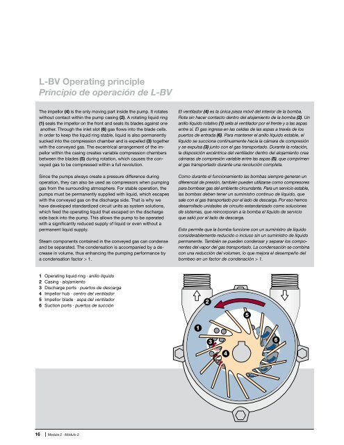
The impellor (4) is the only moving part inside the pump. It rotates<br />
without contact within the pump casing (2). A rotating liquid ring<br />
(1) seals the impellor on the front and seals its blades against one<br />
another. Through the inlet slot (6) gas flows into the blade cells.<br />
In order to keep the liquid ring stable, liquid is also permanently<br />
sucked into the compression chamber and is expelled (3) together<br />
with the conveyed gas. The excentrical arrangement of the impellor<br />
within the casing creates variable compression chambers<br />
between the blades (5) during rotation, which causes the conveyed<br />
gas to be compressed within a full revolution.<br />
Since the pumps always create a pressure difference during<br />
operation, they can also be used as compressors when pumping<br />
gas from the surrounding atmosphere. For stable operation, the<br />
pumps must be permanently supplied with liquid, which escapes<br />
with the conveyed gas on the discharge side. That is why we<br />
have developed standardized circuit units as system solutions,<br />
which feed the operating liquid that escaped on the discharge<br />
side back into the pump. This allows the pump to be operated<br />
with a significantly reduced supply of liquid or even without a<br />
permanent liquid supply.<br />
Steam components contained in the conveyed gas can condense<br />
and be separated. The condensation is accompanied by a decrease<br />
in volume, thus enhancing the pumping performance by<br />
a condensation factor > 1.<br />
1 Operating liquid ring · anillo líquido<br />
2 Casing · alojamiento<br />
3 Discharge ports · puertos de descarga<br />
4 Impellor hub · centro <strong>del</strong> ventilador<br />
5 Impellor blade · aspa <strong>del</strong> ventilador<br />
6 Suction ports · puertos de succión<br />
16 | Module 2 · <strong>Módulo</strong> 2<br />
El ventilador (4) es la única pieza móvil <strong>del</strong> interior de la bomba.<br />
Rota sin hacer contacto dentro <strong>del</strong> alojamiento de la bomba (2). Un<br />
anillo líquido rotativo (1) sella al ventilador por el frente y a las aspas<br />
entre sí. El gas ingresa en las celdas de las aspas a través de los<br />
puertos de entrada (6). Para mantener el anillo líquido estable, el<br />
líquido se succiona continuamente hacia la cámara de compresión<br />
y se expulsa (3) junto con el gas transportado. Durante la rotación,<br />
la disposición excéntrica <strong>del</strong> ventilador dentro <strong>del</strong> alojamiento crea<br />
cámaras de compresión variable entre las aspas (5), que comprimen<br />
el gas transportado durante una revolución completa.<br />
Como durante el funcionamiento las bombas siempre generan un<br />
diferencial de presión, también pueden utilizarse como compresores<br />
para bombear gas <strong>del</strong> ambiente circundante. Para un servicio estable,<br />
las bombas deben tener un suministro continuo de líquido, que<br />
sale con el gas transportado por el lado de descarga. Por eso hemos<br />
desarrollado unidades de circuito estandarizado como soluciones<br />
de sistemas, que reincorporan a la bomba el líquido de servicio<br />
que salió por el lado de descarga.<br />
Esto permite que la bomba funcione con un suministro de líquido<br />
considerablemente reducido o incluso sin un suministro de líquido<br />
permanente. También se pueden condensar y separar los componentes<br />
<strong>del</strong> vapor <strong>del</strong> gas transportado. La condensación se combina<br />
con una reducción <strong>del</strong> volumen, lo que mejora el desempeño <strong>del</strong><br />
bombeo en un factor de condenación > 1.