e-Book PDF - Universidad de La Punta (ULP)
e-Book PDF - Universidad de La Punta (ULP)
e-Book PDF - Universidad de La Punta (ULP)

You also want an ePaper? Increase the reach of your titles
YUMPU automatically turns print PDFs into web optimized ePapers that Google loves.
»<br />
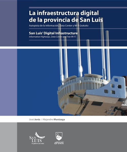
<strong>La</strong> infraestructura digital<br />
<strong>de</strong> la provincia <strong>de</strong> San Luis<br />
Autopista <strong>de</strong> la Información, Data Center y Wi-fi Gratuito<br />
Digital Infrastructure in the Province<br />
of San Luis<br />
Information Highway, Data Center and Free WiFi<br />
José Jerez / Alejandro Munizaga
Jerez, José<br />
<strong>La</strong> infraestructura digital <strong>de</strong> la provincia <strong>de</strong> San Luis : autopista <strong>de</strong> la informacion, data<br />
center, wi fi gratutito / Jose Jerez y Alejandro Munizaga. - 1a ed. - <strong>La</strong> <strong>Punta</strong> : <strong>Universidad</strong><br />
<strong>de</strong> <strong>La</strong> <strong>Punta</strong>, 2010.<br />
E<strong>Book</strong>.<br />
ISBN 978-987-25828-2-1<br />
1. Informática. I. Munizaga, Alejandro II. Título<br />
CDD 005.3<br />
Fecha <strong>de</strong> catalogación: 20/04/2010<br />
Coordinación General<br />
Nestor Arellano<br />
Edición<br />
Darío Cal<strong>de</strong>rón<br />
Diseño<br />
Rocío Juárez<br />
Fotografía<br />
Jorge Andiñach, Archivo <strong>ULP</strong><br />
Traducción<br />
Lucía Zuppa<br />
Diseño <strong>de</strong> tapa<br />
Diego González<br />
Colaboración<br />
Mario Alcaraz<br />
1ª edición<br />
ISBN: 978-987-25828-2-1<br />
© <strong>Universidad</strong> <strong>de</strong> <strong>La</strong> <strong>Punta</strong>, 2010<br />
Queda hecho el <strong>de</strong>pósito que establece la Ley 11.723<br />
Libro <strong>de</strong> edición argentina<br />
No se permite la reproducción parcial o total, el almacenamiento, el alquiler, la<br />
transmisión o la transformación <strong>de</strong> este libro, en cualquier forma o por cualquier medio,<br />
sea electrónico o mecánico, mediante fotocopias, digitalización u otros métodos sin el<br />
permiso previo y escrito <strong>de</strong>l editor. Su infracción está penada por las leyes 11.723 y 25.446
»<br />
<strong>La</strong> infraestructura digital<br />
<strong>de</strong> la provincia <strong>de</strong> San Luis<br />
Autopista <strong>de</strong> la Información, Data Center y Wi-fi Gratuito<br />
Digital Infrastructure in the Province<br />
of San Luis<br />
Information Highway, Data Center and Free WiFi
»<br />
Prólogo<br />
San Luis Digital:<br />
trazando el camino hacia el futuro<br />
El conocimiento pulsó el click <strong>de</strong> una nueva revolución para la humanidad y en<br />
nuestro planeta se viven tiempos exponenciales. <strong>La</strong>s innovaciones, cada vez<br />
más frecuentes, reconfiguran todo lo conocido y las socieda<strong>de</strong>s las adoptan a<br />
mayor velocidad.<br />
Atravesamos una tormenta perfecta que afecta todos los aspectos <strong>de</strong> la vida<br />
cotidiana. Y ante su inexorabilidad es necesario prestar atención a los cuatro<br />
factores que la componen: la revolución tecnológica, la revolución económica,<br />
la revolución social; y la participación <strong>de</strong> la generación <strong>de</strong> nativos digitales y<br />
jóvenes, que sientan un prece<strong>de</strong>nte histórico: por primera vez, ellos saben más<br />
<strong>de</strong> un tema que sus padres.<br />
El futuro no se pue<strong>de</strong> pre<strong>de</strong>cir, pero se pue<strong>de</strong> participar en su invención en forma<br />
colaborativa, con todos los integrantes <strong>de</strong> una sociedad formada, capacitada,<br />
interesada, que disponga <strong>de</strong>l conocimiento para generar innovaciones que<br />
optimicen la productividad y el <strong>de</strong>sarrollo económico.<br />
| 5<br />
San Luis Digital: tracing the road to the future<br />
Knowledge clicked on a new revolution for humanity and our planet is living exponential<br />
times. Innovations are more and more frequent and reconfigure everything that is known and<br />
societies adopt them at a faster rate.<br />
We are going through a perfect storm that affects all aspects of daily life. Facing its inevitability,<br />
it is necessary to pay attention to the four factors that make it up: technological revolution,<br />
economic revolution, social revolution and the participation of digital natives and youngsters<br />
who establish a historical prece<strong>de</strong>nt: for the first time they know more about a topic than their<br />
own parents.<br />
Future cannot be predicted, but we can participate in its invention in a collaborative way, with<br />
all the members of a society, trained, interested and that owns the knowledge to generate<br />
innovations that will optimize the productivity and economic <strong>de</strong>velopment.<br />
We want our inhabitants to take advantage of the possibilities of this storm level 6. We have<br />
therefore, planned and executed, systematically and coherently a 20-years plan, San Luis Digital.
Queremos que quienes habitan nuestro suelo puedan<br />
aprovechar las posibilida<strong>de</strong>s <strong>de</strong> esta tormenta <strong>de</strong> categoría<br />
6. Para esto hemos planificado y ejecutamos, en forma<br />
sistemática y coherente, un plan a 20 años, San Luis Digital.<br />
Nuestra agenda digital se estructura en seis ejes:<br />
Infraestructura, Educativo, Tecnológico, Productivo, Marco<br />
Legal y Gobierno Electrónico.<br />
Hoy tenemos más <strong>de</strong> 235 iniciativas para lograr:<br />
• Exportar más productos con contenido tecnológico.<br />
• Generar una red <strong>de</strong>nsa <strong>de</strong> usuarios <strong>de</strong> Internet<br />
—inclusión digital <strong>de</strong> toda la población—.<br />
• Contar con más profesionales en ciencia e ingenierías<br />
• Y, sobre todo, tener una base más amplia <strong>de</strong> trabajadores<br />
con educación secundaria completa y con mejores<br />
habilida<strong>de</strong>s en matemática, lectura, escritura, ciencia y<br />
tecnologías <strong>de</strong> la información y la comunicación (Tics).<br />
Algunas cifras testimonian elocuentemente el grado <strong>de</strong><br />
avance <strong>de</strong> San Luis en materia tecnológica y educativa<br />
—políticas clave <strong>de</strong> cara al futuro—.<br />
• Todas las localida<strong>de</strong>s con más <strong>de</strong> veinte habitantes tienen<br />
internet <strong>de</strong> banda ancha gratuita a través <strong>de</strong> Wi-Fi.<br />
• El 70% <strong>de</strong> los hogares sanluiseños cuentan con al menos<br />
una computadora.<br />
• <strong>La</strong> penetración <strong>de</strong> Internet es <strong>de</strong>l 74,2%, la más alta <strong>de</strong>l<br />
país, por encima <strong>de</strong> la media nacional que es <strong>de</strong>l 50,3%.<br />
En lo que respecta al sector educativo, las acciones abarcan<br />
a docentes y alumnos.<br />
• El 85% <strong>de</strong> los educadores <strong>de</strong>l sistema educativo<br />
provincial han sido formados en las nuevas tecnologías,<br />
matemática, astronomía, y geotecnologías.<br />
• El 50% <strong>de</strong> las escuelas rurales tienen planes <strong>de</strong><br />
mejoramiento <strong>de</strong> la enseñanza en las disciplinas<br />
estratégicas: matemática, lengua, ciencia y tics.<br />
• Contamos con 42 Centros <strong>de</strong> Inclusión Digital (CID),<br />
distribuidos en todo el territorio, que permiten formar<br />
a las comunida<strong>de</strong>s en el uso <strong>de</strong> las nuevas tecnologías<br />
para mejorar su calidad <strong>de</strong> vida. Los mayores <strong>de</strong> 16<br />
años pue<strong>de</strong>n asistir a estos centros para completar su<br />
escolaridad primaria y secundaria. Durante el 2009 la<br />
asistencia a estos centros fue masiva.<br />
6 |<br />
Our digital agenda is structured into six cores: Infrastructure,<br />
Educational, Technological, Productive, Legal Framework and Digital<br />
Government.<br />
We currently have 235 initiatives to be fulfilled:<br />
• To export more products of technological content<br />
• To generate a <strong>de</strong>nser net of Internet’s users- digital inclusion of the<br />
population-.<br />
• To have more professionals in the area of sciences and engineering.<br />
• And, above all, to have a broa<strong>de</strong>r workers’ data base with complete<br />
higher education and with the best skills in mathematics,<br />
reading, writing, science and information and communication<br />
technologies (ICTs).<br />
Some figures expressively show the progress’ <strong>de</strong>gree of San Luis as far as<br />
technology and education are concerned- key policies facing the future-.<br />
• Every town with more than 20 inhabitants has broad band wireless<br />
internet connection.<br />
• 70% of homes in San Luis have at least one computer<br />
• Internet Penetration rate is 74,2% the highest of the country, above<br />
national average which is 50,3%.<br />
As for the educational sector, actions inclu<strong>de</strong> teachers and stu<strong>de</strong>nts.<br />
• 85% of teachers of the provincial educational system have been<br />
trained in new technologies, mathematics, astronomy and<br />
geotechnologies.<br />
• 50% of rural schools have improvement plans for teaching in strategic<br />
disciplines such as mathematics, language, science and ICTs.<br />
• We have 42 Digital Inclusion Centers (DIC) located across the<br />
province and which allow training the communities in the use of<br />
new technologies to improve their life quality. Youngster over 16<br />
years of age can attend these centers to fulfill their compulsory<br />
schooling. During 2009 attendance to these centers was massive.<br />
• Todos los Chicos en la Red (All kids online) is the plan through<br />
which stu<strong>de</strong>nts from first to sixth gra<strong>de</strong> and their teachers, from<br />
30 localities received a computer each. Its objective is to improve<br />
educational quality. In this way, kids in San Luis study with a<br />
computer with an educational software and free wi-fi connectivity<br />
not only at school but also at home and with teachers that inclu<strong>de</strong><br />
the ICTs in their pedagogical targets.<br />
• Stu<strong>de</strong>nts involved in this plan are also engaged in the environmental,<br />
digital and collaborative initiative Balance Cero (Zero<br />
Balance) that calculates emissions of carbon dioxi<strong>de</strong> produced to
• Todos los Chicos en la Red es el plan por el cual todos<br />
los alumnos <strong>de</strong> primero a sexto grado, <strong>de</strong> treinta<br />
localida<strong>de</strong>s, recibieron una computadora, al igual que<br />
sus maestros. Tiene como objetivo mejorar la calidad<br />
educativa. Alcanza al 14% <strong>de</strong> los estudiantes <strong>de</strong><br />
primaria. De este modo, los niños <strong>de</strong> San Luis estudian<br />
con una computadora, con software educativo y<br />
conectividad a internet tanto en la escuela como en<br />
sus hogares, con docentes que incluyen Tics en sus<br />
prácticas pedagógicas.<br />
• Con los estudiantes <strong>de</strong> este plan se implementa la<br />
propuesta colaborativa medioambiental y digital<br />
Balance Cero, que consiste en calcular el dióxido <strong>de</strong><br />
carbono emitido producto <strong>de</strong> la generación <strong>de</strong> energía<br />
eléctrica que se consume en los hogares. Determinada<br />
la cantidad dióxido <strong>de</strong> carbono se calcula la cantidad<br />
<strong>de</strong> árboles necesarios para capturar ese gas y lograr el<br />
balance entre emisión y captura. Con esta iniciativa,<br />
13 localida<strong>de</strong>s izaron la ban<strong>de</strong>ra <strong>de</strong> balance cero, y en<br />
otras 17 se está plantando. Este año se sumarán como<br />
parte <strong>de</strong> Balance Cero, acciones <strong>de</strong> compensación para<br />
el transporte, la calefacción y los residuos.<br />
• Para alentar el esfuerzo y el estudio todos los años se<br />
realizan las Olimpíadas Sanluiseñas <strong>de</strong>l Conocimiento,<br />
dirigidas a estudiantes <strong>de</strong> primaria y secundaria.<br />
Se compite en forma virtual resolviendo tareas en<br />
la plataforma digital <strong>de</strong> aprendizaje (e-learning) <strong>de</strong><br />
la <strong>Universidad</strong>. Los ganadores reciben importantes<br />
premios. En su edición <strong>de</strong> 2009, los ganadores <strong>de</strong>l<br />
secundario viajaron a Italia a conocer los lugares don<strong>de</strong><br />
Galileo Galilei estudió y enseñó.<br />
• También alentamos la lectura por su crucial importancia<br />
en el <strong>de</strong>sarrollo <strong>de</strong> habilida<strong>de</strong>s intelectuales. Como es<br />
sabido, el pensamiento se estructura con palabras y<br />
la capacidad lingüística hace la diferencia a la hora <strong>de</strong><br />
interpretar y compren<strong>de</strong>r el mundo. Por ello, <strong>de</strong>sarrollamos<br />
el plan <strong>de</strong> lectura Contextos en instituciones educativas<br />
y centros <strong>de</strong> salud. Actualmente, se trabaja con chicos<br />
<strong>de</strong> nivel inicial y hasta segundo grado <strong>de</strong>l primario, en<br />
espacios <strong>de</strong> lectura con bibliografía especializada y<br />
personal que lee para introducir a los pequeños en el<br />
mundo <strong>de</strong> las letras. Con esta propuesta se ha llegado al<br />
50% <strong>de</strong> los niños <strong>de</strong> nivel inicial.<br />
• Con un enfoque centrado en amigar a los jóvenes con<br />
el mundo <strong>de</strong> la programación informática, e interesarlos<br />
| 7<br />
generate electric energy consumed in houses. Once the amount<br />
of carbon dioxi<strong>de</strong> is <strong>de</strong>termined, kids calculate the amount of<br />
trees nee<strong>de</strong>d to capture the gas and reach a balance between<br />
emissions and capture. There are 13 towns so far that have raised<br />
the Zero Balance’s flag and other 17 towns are planting trees. As<br />
part of the Zero Balance project, this year, new activities will be<br />
ad<strong>de</strong>d as for compensations for transport, heating and waste.<br />
• So as to foster effort and study in kids, every year, we carry out San<br />
Luis Knowledge Olympiads address to primary and secondary<br />
school stu<strong>de</strong>nts. Competition is carried out online through the<br />
solution of problems on the digital learning platform (e-learning)<br />
of the University. In its 2009 edition, winners of secondary school<br />
traveled to Italy to visit the places where Galileo Galilei studied<br />
and taught.<br />
• We also encourage reading due to its crucial importance in the<br />
<strong>de</strong>velopment of intellectual activities. It is known that thinking is<br />
structured with words and the linguistic ability makes a difference<br />
when it comes to interpret and un<strong>de</strong>rstand the world. This is why<br />
we <strong>de</strong>velop the plan Contextos (Contexts) in educational institutions<br />
and health care centers. We are currently working with kids<br />
from kin<strong>de</strong>rgarten to second gra<strong>de</strong> of primary school, in special<br />
spots with specialized bibliography and staff who is in charge of<br />
reading so as to introduce kids into the world of letters. We have<br />
reached 50% of kin<strong>de</strong>rgarten’s kids with this plan.<br />
• Focusing in reconciling youngsters with the world of informatics<br />
programming, and so as to get them interested in technological<br />
<strong>de</strong>grees, we organize the Gaming.Net contest together with Microsoft.<br />
In 2009, this contest had 604 youngsters enrolled from 57<br />
schools in 23 different towns. With the same objective, this year we<br />
implement Robot Soccer which implies the use of programming<br />
tools for the <strong>de</strong>velopment of the mobile autonomous robotic.<br />
• In or<strong>de</strong>r to awaken the locals’ interest in science we created <strong>La</strong><br />
<strong>Punta</strong> Astronomical Park (PALP for its name in Spanish). This is a<br />
place for scientific spreading and is ma<strong>de</strong> up of two planetariums, a<br />
fixed one and a traveling one, one observatory with last-generation<br />
<strong>de</strong>vices and the Interactive Center of Science with twelve modules<br />
where different scientific notions are explained. There is also a<br />
naked-eye observatory where we find observational <strong>de</strong>vices used<br />
by different civilizations in the past. 40% of the local population<br />
have visited the PALP and participated in its activities.
por carreras tecnológicas, se organiza el certamen<br />
Gaming.NET junto con Microsoft. En su edición 2009 este<br />
concurso <strong>de</strong> programación contó con 604 inscriptos,<br />
provenientes <strong>de</strong> 57 escuelas, <strong>de</strong> 23 localida<strong>de</strong>s. Con el<br />
mismo objetivo, este año se aña<strong>de</strong> Fútbol Robot, que<br />
implica el uso <strong>de</strong> herramientas <strong>de</strong> programación para<br />
el <strong>de</strong>sempeño en la robótica autónoma móvil.<br />
• Para <strong>de</strong>spertar el interés <strong>de</strong> los puntanos por la<br />
ciencia creamos el Parque Astronómico <strong>La</strong> <strong>Punta</strong><br />
(PALP). Este espacio <strong>de</strong> divulgación científica está<br />
compuesto por dos planetarios, uno fijo y otro<br />
itinerante, un observatorio con dispositivos <strong>de</strong> última<br />
generación, y el Centro Interactivo <strong>de</strong> Ciencias, con<br />
doce módulos don<strong>de</strong> se explican diferentes nociones<br />
científicas. Se aña<strong>de</strong> un observatorio a ojo <strong>de</strong>snudo<br />
conformado por instrumentos <strong>de</strong> observación<br />
utilizados por diferentes pueblos en la antigüedad. El<br />
40% <strong>de</strong> la población sanluiseña ha visitado el PALP y<br />
participado <strong>de</strong> sus propuestas.<br />
Estudios neurocientíficos han <strong>de</strong>mostrado el beneficio<br />
<strong>de</strong> algunos juegos para conseguir un mejor coeficiente<br />
intelectual y una mayor velocidad <strong>de</strong> procesamiento<br />
cerebral. En cinco localida<strong>de</strong>s se ha comenzado con talleres<br />
que incorporan estos juegos específicos, complementados<br />
con arte y música para incentivar en los chicos la expresión<br />
creativa, artística y sensorial.<br />
Estas acciones están dirigidas a preparar a las nuevas<br />
generaciones sanluiseñas en las habilida<strong>de</strong>s que necesitarán<br />
para afrontar el mundo <strong>de</strong>l mañana. Para estar preparados<br />
ante las nuevas ten<strong>de</strong>ncias es importante <strong>de</strong>sarrollar: el<br />
diseño (la forma sobre la función), la narración, la sinfonía<br />
(multicapacidad), la empatía (entendimiento <strong>de</strong>l otro),<br />
el sentido (por sobre la acumulación) y el juego, que<br />
marcarán las pautas <strong>de</strong>l crecimiento socio-económico para<br />
los próximos 50 años.<br />
Nuestra agenda también busca que se radiquen en la<br />
provincia empresas tecnológicas. Con ese fin creamos por<br />
ley el Parque Informático <strong>La</strong> <strong>Punta</strong> (PILP), que actualmente<br />
cuenta con 13 firmas <strong>de</strong> relevancia nacional e internacional.<br />
<strong>La</strong> tecnópolis puntana se emplaza en el campus <strong>de</strong> la <strong>ULP</strong><br />
don<strong>de</strong> confluyen el Estado, la aca<strong>de</strong>mia y la industria.<br />
8 |<br />
Neuroscientific studies have shown the benefit of some games to<br />
achieve a better IQ and a higher speed in brain processing. In five<br />
localities we have started workshops where these specific games were<br />
incorporated complemented with art and music to foster creative,<br />
artistic and sensorial expression in kids.<br />
These actions aim at preparing new local generations in the skills<br />
they will need to face tomorrow’s world. So as to be prepared in front<br />
of the new trends, it is important to <strong>de</strong>velop: the <strong>de</strong>sign (the form<br />
over the function), narration, symphony (multi-ability), empathy (the<br />
un<strong>de</strong>rstanding of the other), the sense (over accumulation) and the<br />
game, that will mark the gui<strong>de</strong>lines for socio-economic growth in the<br />
next 50 years.<br />
Our agenda seeks for technological companies to establish in the<br />
province as well. This is why we created, through law, <strong>La</strong> <strong>Punta</strong><br />
Informatics Park (PILP for its name in Spanish) that currently hosts<br />
13 national and international companies. The local technopolis is<br />
located at the University campus where the State, the University and<br />
the industries converge.<br />
As for the digital government, we plan to digitalize the whole<br />
government system to reach better services that allow citizens<br />
to virtually speed up tasks. San Luis stepped forward with the<br />
implementation of the public key infrastructure (PKI) that allows<br />
the digital signature. Its use in State files is already a fact in several<br />
government bodies.<br />
The success of our programs is backed by the above mentioned<br />
percentages. This figures show the achievements and progresses of a<br />
digital agenda that is <strong>de</strong>veloped in an integral manner paying close<br />
attention to the benefits of the information society.<br />
We build a thriving present, thinking about tomorrow. We plan, we<br />
execute and we make the necessary investments because we are<br />
convinced that this is the road to be part of the invention of the future.<br />
Alberto Rodríguez Saá<br />
April 2010
En cuanto al gobierno electrónico se planifica digitalizar<br />
todo el sistema gubernamental para lograr mejores<br />
servicios, que permitan a los ciudadanos agilizar las<br />
gestiones en forma virtual. San Luis dio un paso <strong>de</strong>cisivo<br />
con la implementación <strong>de</strong> la infraestructura <strong>de</strong> clave<br />
pública (PKI) que posibilita la firma digital. Su aplicación en<br />
expedientes <strong>de</strong> organismos <strong>de</strong>l Estado provincial ya es un<br />
hecho en varias reparticiones.<br />
Construimos un presente próspero, siempre pensando en<br />
mañana. Planificamos, ejecutamos y hacemos las inversiones<br />
necesarias, porque estamos convencidos <strong>de</strong> que este el<br />
camino para participar en la invención <strong>de</strong>l futuro.<br />
Alberto Rodríguez Saá, Abril 2010<br />
El éxito <strong>de</strong> nuestros programas se respalda en los porcentajes<br />
citados. Estas cifras muestran los logros y avances <strong>de</strong> una<br />
agenda digital que se <strong>de</strong>sarrolla <strong>de</strong> modo integral, con la<br />
mirada atenta a un mundo que vive tiempos interesantes.<br />
Estamos inmersos en una revolución científico-tecnológica<br />
y se abren gran<strong>de</strong>s oportunida<strong>de</strong>s para todas las socieda<strong>de</strong>s.<br />
Nosotros en San Luis queremos aprovecharlas. Trabajamos<br />
para que los habitantes <strong>de</strong>l territorio puntano mejoren su<br />
calidad <strong>de</strong> vida y disfruten <strong>de</strong> los beneficios <strong>de</strong> la sociedad<br />
<strong>de</strong> la información.<br />
| 9
»<br />
Des<strong>de</strong><br />
1) - Joseph Stiglitz: economista estadouni<strong>de</strong>nse<br />
nacido en 1943. Obtuvo el Premio Nobel <strong>de</strong><br />
Economía 2001 y la Medalla John Bates Clark<br />
en 1979. Cita extraída <strong>de</strong>l libro “Towards a<br />
New Paradigm in Monetary Economics, with<br />
Bruce Greenwald”, Cambridge University<br />
Press-2003.<br />
Introducción<br />
mediados <strong>de</strong>l siglo XX, la<br />
humanidad vive uno <strong>de</strong> los periodos<br />
<strong>de</strong> mayor celeridad en la<br />
generación, transmisión y asimilación<br />
<strong>de</strong>l conocimiento. Esto, junto<br />
con el <strong>de</strong>sarrollo y afianzamiento<br />
<strong>de</strong> las tecnologías, han revolucionado<br />
el planeta. Se trata <strong>de</strong> un<br />
proceso, que atravesamos, conocido<br />
como Revolución Científico-<br />
Tecnológica.<br />
Después <strong>de</strong> la Segunda Guerra Mundial<br />
el resultado <strong>de</strong> la actividad económica<br />
<strong>de</strong> algunos países comenzó<br />
a <strong>de</strong>pen<strong>de</strong>r menos <strong>de</strong> la transformación<br />
<strong>de</strong> objetos en producción y más<br />
<strong>de</strong> la transformación <strong>de</strong> la base intelectual<br />
<strong>de</strong> la producción.<br />
Hoy, po<strong>de</strong>mos <strong>de</strong>cir que la actividad<br />
económica ha variado en<br />
la medida que se incorporaron a<br />
las organizaciones o instituciones<br />
procesos asociados a crear, planear,<br />
difundir, usar y capitalizar el<br />
conocimiento. Esta nueva economía<br />
se ha <strong>de</strong>nominado Economía<br />
<strong>de</strong>l Conocimiento (EC). Según<br />
Joseph Stiglitz 1 , “la EC ha significado<br />
un cambio trascen<strong>de</strong>ntal <strong>de</strong><br />
dimensiones: el <strong>de</strong>splazamiento <strong>de</strong><br />
la producción <strong>de</strong> bienes a la producción<br />
<strong>de</strong> i<strong>de</strong>as”.<br />
<strong>La</strong>s economías <strong>de</strong>l conocimiento<br />
muestran dinamismo y crecimiento<br />
originados por el uso sistemático<br />
<strong>de</strong> la información, la tecnología<br />
y el conocimiento en la creación<br />
| 11<br />
Introduction<br />
Since the mid-twentieth century, mankind is living one the most accelerated<br />
periods in the generation, transmission and assimilation of<br />
knowledge. This fact, together with the <strong>de</strong>velopment and strengthening<br />
of technology, has revolutionized the planet. This process that we<br />
are going through is known as the Scientific-Technological Revolution.<br />
After the Second World War, the economic activity of some countries<br />
started to <strong>de</strong>pend less of the transformation of objects into products<br />
and to <strong>de</strong>pend more on the transformation of the intellectual foundation<br />
of production.<br />
Nowadays we know that economic activity has changed in the measure<br />
that organizations and institutions have incorporated processes<br />
related to the creation, planning, usage, diffusion and capitalization<br />
of knowledge. This new economy has been named Knowledge<br />
Economy (KE). According to Joseph Stiglitz1, “KE has meant a farreaching<br />
shift of dimensions: moving from the production of goods<br />
to the production of i<strong>de</strong>as”.<br />
Knowledge Economies show dynamism and growth, fueled by the<br />
systematic use of information, technology and knowledge in the<br />
creation of value, in real time that is only feasible because of the technological<br />
infrastructure: ‘Internet”. Technological change and innovation<br />
are the engines of this kind of economy. As this Knowledge<br />
Economy is incorporated in a particular region, a steady increase in<br />
economic <strong>de</strong>velopment is the result and consequently, an increase in<br />
the welfare of society as a whole.<br />
1) -Joseph Stiglitz: American economist born in 1943. He won the Nobel Prize in economics in 2001 and the John Bates Clark medal in 1979. Excerpt from the book “Towards a New<br />
Paradigm in Monetary Economics, with Bruce Greenwald”, Cambridge University Press-2003.
<strong>de</strong> valor, en tiempo real, y con trabajo<br />
en red lo que sólo es factible<br />
gracias a la infraestructura tecnológica:<br />
‘Internet’. Los cambios<br />
tecnológicos y la innovación son<br />
los motores <strong>de</strong> esta economía.<br />
A medida que se incorpora esta<br />
Economía <strong>de</strong>l Conocimiento a una<br />
región particular, se da un mayor<br />
<strong>de</strong>sarrollo económico sostenido y,<br />
por en<strong>de</strong>, colabora con el bienestar<br />
<strong>de</strong> toda la sociedad.<br />
Todos estos cambios socio-económicos<br />
y productivos se enmarcan<br />
en otro proceso que se vive<br />
globalmente <strong>de</strong>nominado Sociedad<br />
<strong>de</strong> la Información (SI). En este<br />
proceso, las socieda<strong>de</strong>s buscan<br />
<strong>de</strong>sarrollar sus mejores potenciales,<br />
mediante la generación e<br />
intercambio <strong>de</strong> la información. <strong>La</strong><br />
SI se caracteriza por basarse en el<br />
conocimiento y en los esfuerzos<br />
por convertir la información en<br />
conocimiento. Cuanto mayor es la<br />
cantidad <strong>de</strong> información generada<br />
por una sociedad, mayor es la<br />
necesidad <strong>de</strong> convertirla en conocimiento.<br />
En la actualidad, a través <strong>de</strong> internet,<br />
la información <strong>de</strong> una sociedad<br />
se genera, transmite y procesa<br />
<strong>de</strong> manera prácticamente instantánea,<br />
sin distinciones geográficas.<br />
Para beneficiarse <strong>de</strong> las oportunida<strong>de</strong>s<br />
<strong>de</strong> la SI, la comunidad <strong>de</strong>be<br />
estar preparada para las evoluciones<br />
económicas, sociales, culturales<br />
y tecnológicas.<br />
Al mismo tiempo, para participar<br />
<strong>de</strong> estas nuevas formas <strong>de</strong> <strong>de</strong>sarrollo<br />
es necesario que la población<br />
esté incluida digitalmente, lo<br />
cual, implica la disminución <strong>de</strong> la<br />
brecha digital. Cuando se habla <strong>de</strong><br />
brecha digital se hace referencia<br />
a la diferencia entre las personas,<br />
comunida<strong>de</strong>s, países y regiones<br />
que usan las nuevas tecnologías<br />
en su vida diaria, y aquellos que<br />
no tienen acceso o no saben cómo<br />
sacarles provecho.<br />
Existen tres pilares, inexorables,<br />
para lograr la inclusión digital:<br />
1) Computadoras y Equipamientos<br />
<strong>de</strong> Red (hardware)<br />
2) Conectividad<br />
3) Formación y Capacitación en<br />
nuevas tecnologías<br />
En este libro <strong>de</strong>sarrollaremos, en especial,<br />
uno <strong>de</strong> ellos: la conectividad.<br />
Definimos “conectividad” como la<br />
capacidad que tiene un individuo<br />
<strong>de</strong> acce<strong>de</strong>r a la red <strong>de</strong> re<strong>de</strong>s, es <strong>de</strong>cir,<br />
<strong>de</strong> conectarse a internet.<br />
12 |<br />
All these social, economic and productive changes take place in the<br />
framework of yet another global process, known as Information Society<br />
(IS). In this process, societies seek to <strong>de</strong>velop their potentials, by<br />
means of the generation and exchange of information. The Information<br />
Society is characterized by being knowledge-based and by<br />
its effort to transform information into knowledge. The larger the<br />
amount of information generated by a society, the larger is the need<br />
to transform it into knowledge.<br />
Currently, through the internet, a society’s information is generated,<br />
transmitted and processed almost instantaneously, without geographical<br />
boundaries. If a community wants to benefit from the opportunities<br />
that the IS provi<strong>de</strong>s, it has to be prepared for economic, social,<br />
cultural and technological evolution.<br />
At the same time, in or<strong>de</strong>r to participate in this new forms of <strong>de</strong>velopment<br />
it is necessary that the population is digitally inclu<strong>de</strong>d, which<br />
implies the reduction of the digital gap. The digital gap refers to the<br />
differences among the persons, communities, countries and regions<br />
that use the new technologies in their everyday life, and those that<br />
either do not have access to these technologies or do not know how<br />
to take advantage of them.<br />
Three inexorable columns must be present in or<strong>de</strong>r to achieve digital<br />
inclusion<br />
1) Computers and Network Equipment (hardware)<br />
2) Connectivity<br />
3) Formation and Training in the new technologies<br />
In this book we will discuss one of these columns particularly: connectivity.<br />
We <strong>de</strong>fine connectivity as the capacity that an individual has to<br />
access the net of networks, or in other words, to access the internet
En San Luis, el Gobierno <strong>de</strong> la Provincia<br />
ejecuta un plan estratégico<br />
a 20 años <strong>de</strong>nominado San Luis Digital,<br />
que ha incluido a la provincia<br />
en la Sociedad <strong>de</strong> la Información y<br />
fomenta la Economía <strong>de</strong>l Conocimiento,<br />
a través <strong>de</strong>l <strong>de</strong>sarrollo<br />
digital, con el objetivo <strong>de</strong> lograr la<br />
prosperidad <strong>de</strong> los sanluiseños.<br />
En busca <strong>de</strong> ese propósito, el gobierno<br />
provincial contrató en el<br />
año 1998 al Ministerio <strong>de</strong> Industria<br />
<strong>de</strong> Canadá para la elaboración<br />
<strong>de</strong> un plan estratégico. En el año<br />
2000, sobre la base <strong>de</strong>l “Plan Maestro<br />
<strong>de</strong> la Autopista <strong>de</strong> la Información<br />
(AUI)”, se realizó la licitación<br />
pública nacional e internacional<br />
para la construcción <strong>de</strong> una red <strong>de</strong><br />
comunicaciones que permitiera<br />
conectar a todo pueblo con más<br />
<strong>de</strong> 20 habitantes.<br />
En el año 2001 se comienza con la<br />
implementación <strong>de</strong> la AUI, que cubre<br />
hoy todo el territorio sanluiseño.<br />
Durante el 2003 se inauguró el<br />
Data Center y la red, es <strong>de</strong>cir, el cerebro<br />
y los brazos <strong>de</strong> la Autopista.<br />
En principio se conectaron todas<br />
las <strong>de</strong>pen<strong>de</strong>ncias <strong>de</strong>l Estado provincial<br />
(Ejecutivo, Legislativo y Judicial),<br />
municipalida<strong>de</strong>s y organismos<br />
no gubernamentales. Durante<br />
los años 2008 y 2009 se llevó la conexión<br />
a toda la sociedad, con el<br />
servicio <strong>de</strong> Wi-Fi gratuito que llega<br />
a todas las ciuda<strong>de</strong>s y localida<strong>de</strong>s<br />
<strong>de</strong> la provincia. Proveer el acceso a<br />
la red, gratuitamente, a través <strong>de</strong><br />
tecnología Wi-Fi, trajo aparejado<br />
una mayor <strong>de</strong>manda sobre la red<br />
<strong>de</strong> la AUI, lo que obligó a mejorar<br />
la infraestructura inicial.<br />
Antes <strong>de</strong> comenzar con el análisis<br />
<strong>de</strong>tallado <strong>de</strong> la AUI, y <strong>de</strong>l servicio<br />
Wi-Fi, resulta importante subrayar<br />
que la conectividad que se ofrece<br />
con el plan San Luis Digital, no un<br />
fin en sí mismo, sino que se trata <strong>de</strong><br />
una herramienta para cumplir con<br />
los objetivos <strong>de</strong>finidos en la agenda<br />
digital <strong>de</strong>l gobierno puntano.<br />
| 13<br />
In San Luis, the Provincial Government is carrying out a 20-year strategic<br />
plan called San Luis Digital that has inclu<strong>de</strong>d the province in the<br />
realm of the Information Society and promotes Knowledge Economy<br />
by means of digital <strong>de</strong>velopment, with the purpose of increasing the<br />
prosperity of the people of San Luis<br />
In or<strong>de</strong>r to achieve that goal the provincial government hired the<br />
Ministry of industry of Canada for the creation of a strategic plan in<br />
1998. In the year 2000, based on the “Master Plan of the Information<br />
Highway (AUI, for its abbreviation in Spanish)” a national and international<br />
public ten<strong>de</strong>r was put out for the construction of a communication<br />
network that would allow the connection of every town with<br />
more than 20 inhabitants.<br />
In the year 2001 the <strong>de</strong>ployment of AUI began, and today it covers the<br />
totality of the province. In 2003 the Data Center and the Network were<br />
inaugurated: in other words, the brain and the arms of the Highway.<br />
At first, all the buildings of the provincial state (Executive, Legislative<br />
and Judicial powers), municipalities and non-governmental organisms<br />
were connected. Throughout the years 2008 and 2009 the society<br />
as a whole was connected, by means of free WiFi service that<br />
reaches all cities and regions of the province. Free access to the net,<br />
through WiFi technology brought a larger <strong>de</strong>mand upon the AUI network,<br />
thus forcing the improvement of the initial infrastructure.<br />
Before we go into a thorough analysis of the AUI and the WiFi service,<br />
it is important to emphasize that the connectivity offered in San Luis<br />
is not an end in itself, but a tool to achieve the goals that have been<br />
<strong>de</strong>fined in the digital agenda of the Government of the Province of<br />
San Luis.
» <strong>La</strong><br />
Capítulo 1:<br />
Autopista <strong>de</strong> la Información<br />
<strong>La</strong> Autopista <strong>de</strong> la Información es<br />
una red <strong>de</strong> telecomunicaciones <strong>de</strong><br />
banda ancha, que permite la conexión<br />
<strong>de</strong> todas las instituciones y<br />
ciudadanos <strong>de</strong> la Provincia <strong>de</strong> San<br />
Luis, con el objetivo <strong>de</strong> transmitir<br />
información en diferentes formatos<br />
(telefonía, datos, vi<strong>de</strong>os, etc.).<br />
Es <strong>de</strong>cir, la AUI es una plataforma<br />
tecnológica <strong>de</strong> telecomunicaciones<br />
y servicios <strong>de</strong> acceso común<br />
por don<strong>de</strong> circula una gran cantidad<br />
<strong>de</strong> información.<br />
datos pue<strong>de</strong>n pasar <strong>de</strong> una parte<br />
a otra <strong>de</strong> la red, atravesando múltiples<br />
enlaces y varios nodos. Esta<br />
red tiene un Data Center, que es el<br />
centro neurálgico o “cerebro”. En él<br />
se concentra y distribuye la información<br />
y se centraliza el alojamiento<br />
y monitoreo <strong>de</strong> la red, y todos los<br />
sistemas informáticos que utiliza el<br />
Gobierno <strong>de</strong> la Provincia.<br />
<strong>La</strong> Autopista está compuesta por<br />
una red <strong>de</strong> enlaces y nodos or<strong>de</strong>nados<br />
<strong>de</strong> tal manera que permiten<br />
la comunicación a distancia. Los<br />
| 15<br />
Chapter 2:<br />
The Information Highway<br />
The Information Highway is a broadband<br />
telecommunications network that allows<br />
the connection of the totality of institutions<br />
and citizens of the province of San Luis, with<br />
the purpose of transmitting information in<br />
different formats (telephone, data, vi<strong>de</strong>o,<br />
etc.). The AUI is a technological platform for<br />
telecommunications and common services,<br />
through which a very large amount of information<br />
flows.<br />
The Highway is composed by a network of<br />
links and no<strong>de</strong>s set up in such a way that<br />
they allow communication over long distances.<br />
Data can travel from one part of the<br />
network to another, going through multiple<br />
links and several no<strong>de</strong>s. This network has a<br />
Data Center, which is the nerve center or the<br />
“brain”. There, all the information is concentrated<br />
and distributed, and the storage and<br />
the monitoring are centralized, as well as all<br />
the information technology systems used by<br />
the Provincial Government.
16 |
2.1 Data Center: El Cerebro <strong>de</strong> la AUI<br />
El DC se encuentra ubicado en la Ciudad <strong>de</strong> <strong>La</strong> <strong>Punta</strong><br />
(ver figura 1) en instalaciones <strong>de</strong>l gobierno provincial,<br />
<strong>de</strong>dicadas exclusivamente a este fin. El predio es <strong>de</strong><br />
aproximadamente 10.000 metros cuadrados y ha sido<br />
elegido estratégicamente por la cercanía a la capital<br />
provincial, la infraestructura <strong>de</strong> servicios disponibles,<br />
el fácil acceso a la zona, y la posibilidad <strong>de</strong> carga y<br />
<strong>de</strong>scarga <strong>de</strong> equipamiento.<br />
El DC <strong>de</strong> San Luis es <strong>de</strong> clase mundial (world class).<br />
Cuenta con arquitectura antisísmica y aislada térmica e<br />
hidrófugamente, sistemas anti-incendios, control ambiental<br />
constante y fuentes <strong>de</strong> energía duplicadas.<br />
Entre los aspectos más <strong>de</strong>stacados <strong>de</strong> la infraestructura<br />
<strong>de</strong>l Data Center se pue<strong>de</strong>n mencionar:<br />
• Capacidad <strong>de</strong> proveer <strong>de</strong> un rango virtualmente<br />
ilimitado <strong>de</strong> instalaciones, a través <strong>de</strong> servidores<br />
virtuales.<br />
| 17<br />
2.1 Data Center: The brain of the AUI<br />
The DC is located in the City of <strong>La</strong> <strong>Punta</strong> (fig.1) in its own facility, property<br />
of the provincial government. The facility covers approximately<br />
10000 square meters, and has been chosen strategically because of<br />
its proximity to the provincial capital, the infrastructure of available<br />
services, easy access and the possibility of loading and unloading of<br />
equipment.<br />
San Luis’ Data Center is a world class one. The architecture of the facility<br />
is anti-seismic, thermally insulated and waterproof,<br />
Among the most important features the data center’s infrastructure<br />
presents:<br />
• Capability to provi<strong>de</strong> a virtually unlimited amount of facilities,<br />
through the use of virtual servers.<br />
• The global infrastructure is based upon a mo<strong>de</strong>l known as “N+1”.<br />
Using this mo<strong>de</strong>l, the AUI, has been able to satisfy the maxi-
• <strong>La</strong> infraestructura global está basada en<br />
el mo<strong>de</strong>lo conocido como “N+1”. Utilizando<br />
este mo<strong>de</strong>lo, la AUI, ha logrado satisfacer<br />
los requerimientos <strong>de</strong> máxima <strong>de</strong>manda,<br />
para sistemas <strong>de</strong> operación crítica.<br />
El sistema “N+1” permite que, ante la falla <strong>de</strong> uno<br />
<strong>de</strong> los componentes <strong>de</strong> la infraestructura (conexión,<br />
equipamientos <strong>de</strong> networking, sistemas<br />
<strong>de</strong> UPS (uninterruptible power supply) -sistema<br />
eléctrico estabilizado e ininterrumpido-, controladores<br />
<strong>de</strong> Aire Acondicionado, etc.), los restantes<br />
componentes tomaran la carga sin reducción <strong>de</strong><br />
<strong>de</strong>sempeño o seguridad.<br />
• Posee un sistema eléctrico redundante para proveer<br />
a todos los usuarios y sistemas críticos potencia<br />
eléctrica limpia y eficiente. El servicio <strong>de</strong> energía<br />
entrante, que brinda la empresa proveedora<br />
<strong>de</strong> servicio eléctrico, es respaldado y sostenido<br />
por un interruptor automático <strong>de</strong> transferencia<br />
y un grupo electrógeno <strong>de</strong> combustible líquido<br />
para actuar ante un corte <strong>de</strong> servicio o baja <strong>de</strong><br />
voltaje.<br />
• Posee un sistema <strong>de</strong> UPS o energía estabilizada redundante.<br />
En caso <strong>de</strong> una falla, el resto <strong>de</strong> las UPS<br />
pue<strong>de</strong>n adquirir la carga sin exce<strong>de</strong>r su capacidad<br />
nominal. <strong>La</strong>s baterías <strong>de</strong> las UPS son cargadas por<br />
la red pública <strong>de</strong> energía eléctrica o por generadores<br />
<strong>de</strong> energía redundantes que posee el DC.<br />
• Dentro <strong>de</strong> la sala <strong>de</strong> equipos, todas las cargas<br />
eléctricas críticas son alimentadas por sistemas<br />
paralelos redundantes <strong>de</strong> UPS, que se configuran<br />
como puente estático automático con circuitos <strong>de</strong><br />
<strong>de</strong>rivación manuales. Cada módulo <strong>de</strong> UPS tiene<br />
su propio banco <strong>de</strong> baterías con suficiente capacidad<br />
para sostener la red eléctrica por periodos<br />
<strong>de</strong> 15 minutos, suficientes para la entrada en régimen<br />
<strong>de</strong> los generadores eléctricos que requieren<br />
60 segundos para su estabilización.<br />
• Los equipos <strong>de</strong> comunicaciones que se alimentan<br />
a 48 Volt <strong>de</strong> corriente continua son provistos<br />
a través <strong>de</strong> sistemas modulares <strong>de</strong> rectificación<br />
<strong>de</strong> energía y están respaldados por baterías secas<br />
que proveen dicha tensión, capaces <strong>de</strong> soportar la<br />
18 |<br />
mum <strong>de</strong>mand requirements for systems of critical operation.<br />
The “N+1” system allows that in the face of failure of one of the<br />
components of the infrastructure (connection, networking equipment,<br />
UPS systems (uninterruptible power supply) –stabilized<br />
and uninterrupted electrical system, air conditioning controllers,<br />
etc.), the remaining components will carry the load, without<br />
affecting performance nor safety.<br />
• It possesses a redundant electrical system to provi<strong>de</strong> clean and<br />
efficient electrical power to both users and critical systems. The<br />
incoming energy system, supplied by the public electricity service<br />
provi<strong>de</strong>r, is backed up and supported by a transference automatic<br />
switch and a liquid fuel electric generator to act in case of<br />
power shortage or low voltage.<br />
• It possesses a UPS system or redundant stabilized energy. In case<br />
of power failure, the remaining UPS can take over the load without<br />
exceeding its nominal capacity. The batteries of the UPS<br />
are charged by the public power supply or by generators of redundant<br />
energy that are located at the DC.<br />
• In the equipment area, all the critical electrical loads are fed by redundant<br />
parallel UPS systems that are configured as automatic<br />
static bridge with manual <strong>de</strong>rivation circuits. Each UPS unit has<br />
its own battery bank with enough capacity to sustain the electric<br />
network for 15 minute periods, which is time enough for the<br />
electrical generators to take over since they require 60 seconds to<br />
stabilize.<br />
• The communication equipment that requires 48 volts of direct<br />
current are fed by energy rectification modular systems and are<br />
backed up by dry batteries that supply the tension and are capable<br />
of withstanding the maximum load for 4 hours.<br />
• The whole Data Center complies with the ground connection
carga máxima durante 4 horas.<br />
• En todo el Data Center se cumple con los estándares<br />
<strong>de</strong> conexión a tierra o puesta a tierra, especificados<br />
y recomendados por las normas ITU-T<br />
Recomendación K-27 y ETS1.<br />
• Se cuenta con un avanzado sistema <strong>de</strong> <strong>de</strong>tección<br />
temprana <strong>de</strong> incendios, que <strong>de</strong>tecta el<br />
humo en las primeras etapas <strong>de</strong> la combustión<br />
y <strong>de</strong> muy alta sensibilidad, y con un sistema <strong>de</strong><br />
extinción automática por inundación total con<br />
agente limpio <strong>de</strong> acción química: gas heptafluoropropano,<br />
también conocido como FM200.<br />
Éste es específico para extinguir fuegos clase<br />
C sin producir daño inmediato o posterior sobre<br />
componentes eléctricos o electrónicos.<br />
El gas agente cumple con las exigencias impartidas<br />
por la SNAP EPA US <strong>de</strong>l programa <strong>de</strong> control<br />
<strong>de</strong> polución ambiental para los Estados Unidos y<br />
con las exigencias impartidas por la IRAM 3696, en<br />
su draft <strong>de</strong> septiembre <strong>de</strong> 2008.<br />
<strong>La</strong>s zonas <strong>de</strong> cobertura abarcan el pleno <strong>de</strong> piso<br />
técnico y el ambiente.<br />
<strong>La</strong>s baterías <strong>de</strong> cilindros principales y <strong>de</strong> reserva<br />
están dispuestas en una sala contigua al área <strong>de</strong><br />
máxima seguridad (Sala <strong>de</strong> equipos) y están diseñados<br />
para operar en un rango <strong>de</strong> temperatura <strong>de</strong><br />
0°C a 55°C. <strong>La</strong> capacidad <strong>de</strong> carga <strong>de</strong> los mismos<br />
fue diseñada en función <strong>de</strong>l área a proteger.<br />
El sistema está diseñado para que la presión generada<br />
por el gas no afecte los cerramientos <strong>de</strong>l<br />
mismo y su estanquidad.<br />
Ante la or<strong>de</strong>n <strong>de</strong> <strong>de</strong>scarga <strong>de</strong> los cilindros <strong>de</strong> gas,<br />
la misma señal que activa la electro válvula, sea<br />
<strong>de</strong> origen manual o <strong>de</strong>s<strong>de</strong> panel <strong>de</strong> incendio, actúa<br />
sobre las entradas <strong>de</strong> emergencia <strong>de</strong> las UPS,<br />
sobre la paradas <strong>de</strong> emergencias <strong>de</strong>l aire acondicionado<br />
y sobre los con conectores que operan<br />
sobre el circuito <strong>de</strong> iluminación <strong>de</strong>l sector. De<br />
esta manera, se logra un apagado completo <strong>de</strong>l<br />
sistema <strong>de</strong> corriente alterna y corriente continua<br />
(baterías), y fundamentalmente, <strong>de</strong> fácil reinicio a<br />
condiciones normales.<br />
• <strong>La</strong> sala <strong>de</strong> equipos esta climatizada por un sistema<br />
<strong>de</strong> precisión con control <strong>de</strong> humedad. Consiste en<br />
| 19<br />
standards, specified and recommen<strong>de</strong>d by ITU-T Recommendation<br />
norms K-27 and ETS1.<br />
• The DC has an advanced early fire <strong>de</strong>tection system that <strong>de</strong>tects<br />
smoke at the first stages of combustion. It is a very sensitive system,<br />
equipped with a total flood automatic extinction system,<br />
which uses a clean chemical action agent, heptaflouropropane,<br />
also known as FM200. This agent is specific for the extinction<br />
of C class fires without harming the electric or electronic components.<br />
The gaseous agent also complies with the requirements<br />
issued by SNAP EPA US, in regards to the environmental<br />
pollution control program in the United States, as well as the<br />
requirements issued by IRAM 3696, in its September 2008 draft.<br />
The technical floor is covered completely by the fire <strong>de</strong>tection<br />
system. The batteries for the main and back up gas cylin<strong>de</strong>rs<br />
are arranged in a room adjacent to the maximum security area<br />
(equipment room), and have been <strong>de</strong>signed to operate at temperatures<br />
ranging from 0°C to 55°C. The load capacity of the batteries<br />
was <strong>de</strong>signed in accordance to the area to be protected.<br />
The system is <strong>de</strong>signed so that there in gas leakage caused by gas<br />
pressure. When the discharge of the gas cylin<strong>de</strong>rs is activated, the<br />
same signal that activates the electro valve, whether it is triggered<br />
manually or from the fire alarm panel, acts upon the emergency<br />
input of the UPS, the emergency stops of the air conditioning<br />
system, and the connectors that operate the sector’s illumination<br />
circuit. This way, a complete shutoff of the direct and alternating<br />
currents (batteries) takes place, and thus facilitates the re-start at<br />
normal conditions.<br />
• The equipment room is air-conditioned by a precision system that<br />
has humidity control. It is a high-efficiency air-con<strong>de</strong>nsation system<br />
that uses R407 cooling gas (ecologically safe). This is a high<br />
quality system, specifically <strong>de</strong>signed for data center environments,<br />
and its <strong>de</strong>sign minimizes the space usage in the plant (mini-
un sistema <strong>de</strong> alta eficiencia, <strong>de</strong> con<strong>de</strong>nsación por<br />
aire, con gas refrigerante R407c (ecológico).<br />
Este sistema es <strong>de</strong> alta calidad, específicamente,<br />
diseñado para ambientes <strong>de</strong> data center y tiene<br />
un diseño <strong>de</strong> minimización <strong>de</strong> ocupación <strong>de</strong> espacio<br />
en planta (mínimo footprint). Los equipos<br />
toman el aire <strong>de</strong> la sala a refrigerar e insuflan el<br />
aire refrigerado por los pisos técnicos que provee<br />
<strong>de</strong> aire climatizado a los rack que alojan los equipos.<br />
Este sistema está diseñado <strong>de</strong> manera tal, <strong>de</strong><br />
optimizar la extracción <strong>de</strong> calor <strong>de</strong> los equipos <strong>de</strong><br />
comunicaciones.<br />
Los equipos <strong>de</strong> aire acondicionado <strong>de</strong> precisión<br />
<strong>de</strong> con<strong>de</strong>nsación por aire están compuestos por<br />
la unidad evaporadora interior y la unidad con<strong>de</strong>nsadora<br />
exterior.<br />
<strong>La</strong> unidad evaporadora contiene la serpentina <strong>de</strong>l<br />
evaporador, ventilador centrífugo <strong>de</strong> transmisión<br />
directa, compresor <strong>de</strong>l tipo scroll, presostatos <strong>de</strong><br />
alta y baja presión, válvula <strong>de</strong> expansión termostática<br />
con ecualización externa, válvulas <strong>de</strong> servicio,<br />
visor <strong>de</strong> líquido, recibidor <strong>de</strong> líquido con válvula<br />
<strong>de</strong> sobrepresión, filtro secador, tablero eléctrico<br />
y control por microprocesador. Mientras que la<br />
unidad con<strong>de</strong>nsadora externa tiene la serpentina<br />
<strong>de</strong>l con<strong>de</strong>nsador, ventilador axial <strong>de</strong> transmisión<br />
directa y regulador electrónico <strong>de</strong> velocidad para<br />
época invernal. El sistema contiene controles microprocesados<br />
incorporados en la propia máquina.<br />
Este sistema es in<strong>de</strong>pendiente <strong>de</strong>l resto <strong>de</strong>l edificio<br />
con capacidad para aten<strong>de</strong>r la <strong>de</strong>manda máxima<br />
<strong>de</strong> calor sensible proyectada, mediante dos<br />
equipos con redundancia y conmutación semanal.<br />
Los sensores <strong>de</strong> temperatura y humedad están<br />
instalados en el flujo <strong>de</strong> retorno <strong>de</strong>l aire, <strong>de</strong>ntro<br />
<strong>de</strong>l gabinete <strong>de</strong>l evaporador. <strong>La</strong>s condiciones <strong>de</strong><br />
alarma <strong>de</strong>berán activar un indicador audiovisual.<br />
Los equipos <strong>de</strong> precisión son <strong>de</strong> alta performance<br />
y redundantes.<br />
<strong>La</strong>s unida<strong>de</strong>s están alimentadas tanto por la red<br />
eléctrica pública como por los sistemas eléctricos<br />
<strong>de</strong> emergencia con los que cuenta el Data Center.<br />
De esta manera, se logra una temperatura <strong>de</strong> 21°C<br />
+/- 2°C con una humedad relativa <strong>de</strong>l 45%.<br />
20 |<br />
mum footprint). The equipment takes the air from the room to<br />
be cooled and pumps the cooled air through the technical floors<br />
that supply air to the racks that store the equipment. This system<br />
is <strong>de</strong>signed in such a way that it optimizes the extraction of heat<br />
from the communication equipment. The precision air conditioning<br />
units are composed by an internal evaporation unit and an<br />
external con<strong>de</strong>nsation unit. The evaporation unit contains the<br />
evaporation coils, direct transmission centrifugal fan, scroll type<br />
compressor, high and low pressure sensors, thermostatic expansion<br />
valve with external equalization, service valves, liquid control,<br />
and liquid receiver equipped with over-pressure valve, drying filter,<br />
electrical panel and microprocessor control. Whereas the external<br />
con<strong>de</strong>nsation unit has the con<strong>de</strong>nsation coils, direct transmission<br />
axial fan and electronic speed regulation for the winter. The system<br />
contains built-in micro-processed controls. This system is<br />
in<strong>de</strong>pen<strong>de</strong>nt form the rest of the building, and has the capacity<br />
to manage the maximum projected sensitive heat, by means of<br />
two pieces of equipment with redundancy and weekly switching.<br />
The temperature and humidity sensors are set up in the air return<br />
flow, insi<strong>de</strong> the evaporator cabinet. The alarm conditions must<br />
activate an audiovisual indicator. The precision equipment is of<br />
high performance and redundant. The units are fed by the public<br />
power supply as well as the emergency electrical systems available<br />
at the Data Center. This way a temperature of 21°C +/- 2° and<br />
a relative humidity of 45% are maintained.<br />
• The security and integrity of the Data center are maintained by<br />
means of closed circuit surveillance, alarms and security personnel,<br />
24 hours a day, 365 days a year. The cameras are mounted<br />
insi<strong>de</strong> and outsi<strong>de</strong> the building, and monitored from a control<br />
center, the vi<strong>de</strong>o saved in magnetic format. The accesses to the<br />
Data Center are controlled by an access control system that inclu<strong>de</strong>s<br />
proximity cards and biometric technology, <strong>de</strong>pending on<br />
the level that is being accessed. All entries and <strong>de</strong>partures are
• <strong>La</strong> seguridad e integridad <strong>de</strong>l DC es mantenida<br />
por un sistema <strong>de</strong> vigilancia vía circuito cerrado<br />
<strong>de</strong> televisión, alarmas y personal las 24 horas <strong>de</strong>l<br />
día, 365 días <strong>de</strong>l año.<br />
<strong>La</strong>s cámaras están montadas <strong>de</strong>ntro y fuera <strong>de</strong>l<br />
edificio y son monitoreadas <strong>de</strong>s<strong>de</strong> un centro <strong>de</strong><br />
control y guardadas en formatos magnéticos.<br />
Los accesos al Data Center son controlados mediante<br />
un sistema <strong>de</strong> control <strong>de</strong> acceso con tarjetas<br />
<strong>de</strong> proximidad y mediante medios biométricos,<br />
según el nivel al que se está accediendo.<br />
Todos los ingresos y egresos son registrados en el<br />
sistema.<br />
A<strong>de</strong>más, se exigen estrictos procedimientos <strong>de</strong> ingreso<br />
para el personal ajeno a la Institución.<br />
permite la comunicación gratuita <strong>de</strong> más <strong>de</strong> 1.400<br />
internos IP y 2.000 internos convencionales.<br />
• El DC posee una solución <strong>de</strong> servidores con tecnología<br />
Bla<strong>de</strong> (ver figura 2). Esta tecnología <strong>de</strong> servidores<br />
con virtualización, permite obtener notables<br />
mejoras en la performance, mayor disponibilidad<br />
<strong>de</strong> servicios, flexibilidad en la administración, disminución<br />
en el espacio físico, y por en<strong>de</strong>, reducir<br />
costos <strong>de</strong> gestión y mantenimiento.<br />
• El Data Center cuenta con altas medidas <strong>de</strong> seguridad<br />
<strong>de</strong> acceso a los datos mediante dispositivos conocidos<br />
como Firewall´s, colocados estratégicamente<br />
para imposibilitar los accesos no autorizados.<br />
• <strong>La</strong> Autopista <strong>de</strong> la Información posee una plataforma<br />
<strong>de</strong> telefonía <strong>de</strong> última generación, que<br />
| 21<br />
registered in the system. Strict admission procedures are established<br />
for visitors not belonging to the institution.<br />
• The Data Center has high security measures concerning data access,<br />
by means of barriers known as Firewalls, strategically set up<br />
to prevent unauthorized access.<br />
• The Information Highway inclu<strong>de</strong>s a latest-generation telephony<br />
platform, that allows free communication for more than 1400 internal<br />
IP and 2000 conventional internal telephones<br />
• The DC possesses a solution of servers that use Bla<strong>de</strong> technology<br />
(fig. 2). This virtualization server technology allows noticeable<br />
improvements in performance, more availability of services, administration<br />
flexibility, reduction of physical space, and therefore<br />
a reduction in the costs of management and maintenance.<br />
Figura 2: servidores con tecnología Bla<strong>de</strong> / Figure 2: Servers with Bla<strong>de</strong><br />
technology
• El almacenamiento <strong>de</strong> datos<br />
se centraliza en equipos <strong>de</strong><br />
storage <strong>de</strong> última generación<br />
que utilizan tecnologías NAS<br />
y SAN, a<strong>de</strong>más usan como infraestructura<br />
<strong>de</strong> interconexión<br />
fiber cannel e iSCSI.<br />
El DC cuenta con un sistema <strong>de</strong><br />
almacenamiento, en Storage,<br />
<strong>de</strong> 42 Terabytes <strong>de</strong> capacidad y<br />
con capacidad <strong>de</strong> crecimiento<br />
hasta 672 Terabytes (ver figura<br />
3). <strong>La</strong> tecnología utilizada en<br />
estos equipos permite tener<br />
en RAID el sistema operativo<br />
y no sólo el aplicativo correspondiente.<br />
Es <strong>de</strong>cir, que en algunos<br />
casos, los sistemas operativos<br />
<strong>de</strong> los servidores están<br />
en los storages <strong>de</strong> la AUI.<br />
22 |<br />
• Data storage is centralized in latest- generation<br />
storage equipment that uses<br />
NAS and SAN technology: the storage<br />
also uses fiber channel and iSCSI as<br />
interconnecting infrastructure. The DC<br />
is equipped with a storage system of<br />
42 terabytes capacity, and a growth<br />
potential of up to 672 terabytes (fig. 3).<br />
The technology used in this equipment<br />
allows having the operative system in<br />
RAID, and not only the corresponding<br />
application, this is to say, in some cases<br />
the operative systems of the servers are<br />
allocated in the AUI storage units.<br />
• The Data Center has VTL (Virtual Tape<br />
Library) technology available and this<br />
Figura 3: storage <strong>de</strong> la AUI / Figure 3: AUI storage
• Se cuenta con tecnología <strong>de</strong>l tipo VTL (Virtual<br />
Tape Library) que permite realizar toda la política<br />
<strong>de</strong> Backups (ver figura 4). Con esta nueva tecnología<br />
se cuenta con mejor velocidad <strong>de</strong> acceso a la<br />
información, que sumados a los beneficios que<br />
brindan las tecnologías <strong>de</strong> <strong>de</strong>duplicación <strong>de</strong> datos<br />
en cuanto a la compresión <strong>de</strong> los mismos, se<br />
ve incrementada la capacidad <strong>de</strong> Backup, recuperación<br />
<strong>de</strong> datos en un menor tiempo, y realización<br />
simultáneamente <strong>de</strong> varios resguardos, etc.<br />
• El equipamiento encargado <strong>de</strong> mantener todos<br />
los servicios brindados por la Autopista <strong>de</strong> la Información<br />
se encuentra dividido en varias plataformas<br />
tecnológicas, <strong>de</strong> las cuales po<strong>de</strong>mos <strong>de</strong>stacar<br />
dos gran<strong>de</strong>s grupos: Plataforma <strong>de</strong> E-government<br />
y Plataforma <strong>de</strong> Hosting.<br />
Figura 4: VTL <strong>de</strong>l Data Center <strong>de</strong> la AUI. / Figure 4: Data Center’s VTL<br />
<strong>La</strong> primera plataforma tiene a cargo el Sistema Integral<br />
<strong>de</strong> Gestión <strong>de</strong> Gobierno Electrónico (SIGGE), que<br />
está conformado por más <strong>de</strong> veinticinco aplicativos<br />
usados por diferentes entes gubernamentales, entre<br />
ellos: Salud (SISA), Registro Civil (SIRC), Seguridad<br />
| 23<br />
allows carrying out the Backup policy (fig. 4). This new technology<br />
allows for faster information access, which ad<strong>de</strong>d to the<br />
benefits provi<strong>de</strong>d by <strong>de</strong>duplication technology in regards to data<br />
compression, increased backup capacity, data retrieval time and<br />
simultaneous performance of several safeguards, etc.<br />
• The equipment in charge of maintaining all the services provi<strong>de</strong>d<br />
by the Information Highway is divi<strong>de</strong>d in several technological<br />
platforms, among which we can emphasize two<br />
big groups: E-Government Platform and Hosting Platform.<br />
The former is in charge of the Integral System of Electronic<br />
Government Management (SIGGE, by its initials in Spanish),<br />
which is ma<strong>de</strong> up by more than twenty-five systems used by<br />
different governmental entities, among others: Health (SISA),<br />
Registry (SIRC), Security (SISE), Social Inclusion Plan (SIIS).<br />
The E-Government Platform has a 3-layer architecture. This<br />
means that the application data, the interface as well as the logic<br />
of the mo<strong>de</strong>l do not resi<strong>de</strong> in the same i<strong>de</strong>ntity, but that each has<br />
its own i<strong>de</strong>ntity. These layers are:<br />
- <strong>La</strong>yer 1: Front End. Application Client<br />
- <strong>La</strong>yer 2: Back End. Applications Server<br />
- <strong>La</strong>yer 3: Database. Data Server<br />
The platform involves Microsoft technology for most of the servers<br />
that compose it, but there also Linux-based applications. The databases<br />
are Oracle EE, and Microsoft’s SQL Server.<br />
The second platform has a three layer architecture as well. The hosting<br />
service that belongs to the Government of the Province of San<br />
Luis is supported by the second platform. This service currently hosts<br />
more than one hundred sites. Besi<strong>de</strong>s, comparing it to the commercial<br />
platforms, it is one of the few that can support different webprogramming<br />
technologies.
(SISE), Plan <strong>de</strong> Inclusión (SIIS), entre<br />
otros.<br />
<strong>La</strong> plataforma <strong>de</strong> E-government<br />
<strong>de</strong>sarrolla una arquitectura <strong>de</strong> 3<br />
capas. Esto quiere <strong>de</strong>cir, que tanto<br />
los datos <strong>de</strong> la aplicación, como la<br />
interfaz, como la lógica <strong>de</strong> mo<strong>de</strong>lo<br />
no resi<strong>de</strong>n en la misma i<strong>de</strong>ntidad,<br />
sino que cada capa posee su i<strong>de</strong>ntidad.<br />
Estas capas son:<br />
• Capa 1: Front End. Cliente <strong>de</strong><br />
aplicación<br />
• Capa 2: Back End. Servidor <strong>de</strong><br />
aplicaciones<br />
• Capa 3: Database. Servidor <strong>de</strong><br />
datos<br />
<strong>La</strong> plataforma involucra tecnología<br />
Microsoft, para la mayoría <strong>de</strong><br />
los servidores que la componen,<br />
pero también existen aplicaciones<br />
sobre Linux. <strong>La</strong>s bases <strong>de</strong> datos<br />
son Oracle EE <strong>de</strong> Oracle y SQL Server<br />
<strong>de</strong> Microsoft.<br />
<strong>La</strong> segunda plataforma también<br />
<strong>de</strong>sarrolla una arquitectura en tres<br />
capas. De ella proviene el servicio<br />
<strong>de</strong> hosting perteneciente al Gobierno<br />
<strong>de</strong> la Provincia <strong>de</strong> San Luis.<br />
Este servicio posee actualmente<br />
más <strong>de</strong> cien sitios hosteados.<br />
A<strong>de</strong>más, comparada con la oferta<br />
comercial, es <strong>de</strong> las pocas que soportan<br />
diferentes tecnologías <strong>de</strong><br />
programación web.<br />
<strong>La</strong> AUI ofrece diversas opciones <strong>de</strong><br />
conectividad a los ciudadanos, a<br />
través <strong>de</strong> un diseño <strong>de</strong> comunicaciones<br />
redundantes y efectivo.<br />
Dentro <strong>de</strong>l esquema <strong>de</strong> trabajo <strong>de</strong><br />
la AUI se dispone <strong>de</strong> un Centro <strong>de</strong><br />
Contactos (CC), que está instalado<br />
en el Data Center, con capacidad<br />
para treinta puestos, más un supervisor<br />
y una configuración <strong>de</strong><br />
recursos, y servicios acor<strong>de</strong>s a los<br />
requerimientos <strong>de</strong> los usuarios <strong>de</strong><br />
la AUI. Cada agente <strong>de</strong> este centro<br />
<strong>de</strong> atención cuenta con el equipamiento,<br />
tanto <strong>de</strong> hardware como<br />
<strong>de</strong> software, necesario para su correcto<br />
<strong>de</strong>sempeño.<br />
El Centro <strong>de</strong> Contactos brinda soporte<br />
<strong>de</strong> primer nivel a todos los<br />
usuarios <strong>de</strong> los servicios informáticos<br />
que brinda el Gobierno <strong>de</strong><br />
San Luis, a través <strong>de</strong> la AUI. A<strong>de</strong>más,<br />
colabora con la formación <strong>de</strong><br />
recursos, ya que brinda pasantías<br />
laborales a los alumnos <strong>de</strong> la <strong>Universidad</strong><br />
<strong>de</strong> <strong>La</strong> <strong>Punta</strong> (<strong>ULP</strong>). Esto<br />
significa una ayuda económica y<br />
un paso previo importante para<br />
una pronta inserción laboral, que<br />
24 |<br />
The AUI offers several connectivity options to the citizens, by means of<br />
a redundant and effective communications <strong>de</strong>sign.<br />
Within the AUI’s work diagram there is a Contact Center (CC), allocated<br />
in the Data Center, with a capacity for 30 positions, a supervisor,<br />
a resource configuration, and services in accordance to the requirements<br />
of the AUI users. Each agent at this attention center has the<br />
hardware and the software nee<strong>de</strong>d for appropriate performance.<br />
The Contact Center provi<strong>de</strong>s first level support to all users of the services<br />
offered by the Government of San Luis, through the AUI. It also<br />
contributes with the formation of human resources, by offering internships<br />
to the stu<strong>de</strong>nts of <strong>Universidad</strong> <strong>de</strong> la <strong>Punta</strong> (<strong>ULP</strong>). This implies<br />
financial support and important experience for the stu<strong>de</strong>nts’ insertion<br />
in the work market, including the possibility of working at the Information<br />
Highway’s Data center itself. Through the CC, the Highway<br />
provi<strong>de</strong>s quick support for the users’ queries, and at the same time it<br />
receives the feedback from the users’ opinions, which allows improving<br />
the services if necessary.<br />
Working as support at a second level, there exists an area called Monitoring,<br />
which is in charge of integrating all the alarms, operations,<br />
elements and activities of the AUI net. This way, it is possible to eliminate<br />
problems before they occur. This area uses analysis tools and<br />
monitoring of network, servers and systems, in real time that allow<br />
preventing problems and improving the efficiency of the service.<br />
The Data Center also has a Network Operation Center (NOC) where<br />
the administration of each service is carried out, as well as the administration<br />
of the network as a whole. This area fulfills the third level<br />
support tasks.
colabora en la incorporación <strong>de</strong><br />
conocimientos y posibilita, en<br />
ciertas ocasiones, una carrera laboral<br />
<strong>de</strong>ntro <strong>de</strong>l DC <strong>de</strong> la AUI. A<br />
través <strong>de</strong>l CC, la Autopista brinda<br />
rápidas respuestas a los usuarios<br />
y, al mismo tiempo, sirve como<br />
retroalimentación, ya que a través<br />
<strong>de</strong>l mismo se logra obtener la percepción<br />
<strong>de</strong>l usuario en referencia<br />
a los servicios brindados, para así<br />
po<strong>de</strong>r tomar acciones <strong>de</strong> mejora<br />
en caso <strong>de</strong> ser necesarias.<br />
Como soporte <strong>de</strong> segundo nivel,<br />
existe un área <strong>de</strong>nominada Monitoreo,<br />
que se encarga <strong>de</strong> integrar<br />
todas las alarmas, operaciones,<br />
elementos y las activida<strong>de</strong>s <strong>de</strong> red<br />
<strong>de</strong> la AUI. De este modo, es posible<br />
eliminar los probables inconvenientes<br />
antes <strong>de</strong> que sucedan.<br />
Este área utiliza herramientas <strong>de</strong><br />
análisis y monitoreo <strong>de</strong> re<strong>de</strong>s, servidores<br />
y aplicativos, en tiempo<br />
real, que permiten la previsión <strong>de</strong><br />
problemas y la mejora en la eficiencia<br />
<strong>de</strong> los servicios.<br />
También, el DC cuenta con un<br />
NOC (Network Operation Center)<br />
o Centro <strong>de</strong> Operaciones <strong>de</strong> la Red<br />
en don<strong>de</strong> se realizan la administración<br />
<strong>de</strong> cada servicio, y <strong>de</strong> la red<br />
en su totalidad. Esta área cumple<br />
las funciones <strong>de</strong> soporte <strong>de</strong> tercer<br />
nivel.<br />
Resulta importante <strong>de</strong>stacar que<br />
el Data Center <strong>de</strong> la AUI utiliza estándares<br />
abiertos para sus plataformas<br />
tecnológicas, esto asegura<br />
la interoperabilidad entre distintos<br />
fabricantes <strong>de</strong> equipamientos. <strong>La</strong>s<br />
diferentes funcionalida<strong>de</strong>s, base<br />
<strong>de</strong> datos y lógica <strong>de</strong> negocios, son<br />
distribuidas en ‘capas’ separadas<br />
para permitir futuros crecimientos<br />
y upgra<strong>de</strong>s, <strong>de</strong> manera rápida y<br />
sencilla, que aseguran la alta disponibilidad<br />
<strong>de</strong>l sistema.<br />
Lo expresado asegura que el Data<br />
Center <strong>de</strong> San Luis sea <strong>de</strong> clase<br />
mundial con seguridad física, lógica,<br />
operativa y funcional garantizada,<br />
que permite su operatividad<br />
las 24 horas, los 365 días <strong>de</strong>l año,<br />
con el respaldo <strong>de</strong> un grupo profesional<br />
<strong>de</strong> trabajo.<br />
| 25<br />
It is important to point out that the Data Center of the AUI uses open<br />
standards for its technological platforms, ensuring the compatibility<br />
among different equipment manufacturers. The different functionalities,<br />
databases, and business logic are distributed in separated ‘layers’<br />
in or<strong>de</strong>r to allow future expansion and upgra<strong>de</strong>s, in a quick and simple<br />
manner, that ensure the system high availability.<br />
For all these reasons, the Data Center in San Luis is a world class facility,<br />
with guaranteed physical, logical, operational and functional<br />
security that allows its operation 24 hours a day, 365 days a year, supported<br />
by a professional work team.
2.2 Infraestructura <strong>de</strong> Red: Los brazos <strong>de</strong> la AUI<br />
<strong>La</strong> Autopista <strong>de</strong> la Información proporciona conectividad<br />
a todas las localida<strong>de</strong>s <strong>de</strong> la Provincia <strong>de</strong> San<br />
Luis, con más <strong>de</strong> veinte habitantes. Para ello utiliza<br />
una red IP, que es la más gran<strong>de</strong> red gubernamental<br />
<strong>de</strong> la República Argentina.<br />
<strong>La</strong> red IP <strong>de</strong> banda ancha, <strong>de</strong> la AUI, es <strong>de</strong> tecnología<br />
híbrida ya que utiliza enlaces <strong>de</strong> fibra óptica, radio<br />
enlaces y enlaces satelitales. Esta red está compuesta<br />
por un po<strong>de</strong>roso backbone principal en forma <strong>de</strong><br />
anillo y una capa <strong>de</strong> agregación, y última milla, con<br />
topología estrella. También, se dispone en la ciudad<br />
capital y Villa Merce<strong>de</strong>s <strong>de</strong> una infraestructura <strong>de</strong> red<br />
metropolitana <strong>de</strong> fibra óptica que se conectan al backbone<br />
principal.<br />
2.2.1 Backbone IP: <strong>La</strong> Columna vertebral<br />
El backbone <strong>de</strong> la red IP, es <strong>de</strong>cir la columna vertebral<br />
<strong>de</strong> la red, está formado por un conjunto <strong>de</strong> nodos y<br />
enlaces que recorren las principales ciuda<strong>de</strong>s <strong>de</strong> San<br />
Luis (ver figura 5).<br />
26 |<br />
2.2 Web Infrastructure: The arms of the AUI<br />
Figura 5: esquema Backbone IP / Figure 5: Backbone IP diagram<br />
The Information Highway provi<strong>de</strong>s connectivity to all localities that<br />
have more than twenty inhabitants in the whole Province of San Luis.<br />
To achieve this, an IP net is used, the largest governmental net in Argentina.<br />
The AUI’s broadband IP net uses hybrid technology since it uses fiber<br />
optic links, radio links and satellite links. This network is composed by<br />
a powerful main backbone, shaped as a ring and an aggregation layer,<br />
last mile with star topology. There is also, in the capital city and in<br />
the city of Villa Merce<strong>de</strong>s, a metropolitan fiber optic net infrastructure<br />
that connects to the main backbone.
El backbone principal está compuesto <strong>de</strong> treinta y<br />
seis nodos ubicados, estratégicamente, con el objeto<br />
<strong>de</strong> conectar <strong>de</strong>s<strong>de</strong> allí todos los nodos secundarios<br />
y <strong>de</strong> estos últimos los enlaces <strong>de</strong> última milla, los <strong>de</strong><br />
acceso al usuario.<br />
2.2.2 Los Shelter´s <strong>de</strong> la AUI<br />
En cada nodo principal se encuentran los equipos <strong>de</strong><br />
comunicaciones necesarios para que la red funcione.<br />
Los mismos están dispuestos en un shelter.<br />
Un shelter es un cerramiento tipo contenedor que<br />
permite alojar equipos electrónicos o <strong>de</strong> telecomunicaciones,<br />
altamente sensibles, en un ambiente controlado<br />
y apto para el correcto funcionamiento (ver<br />
figura 6).<br />
<strong>La</strong>s principales características <strong>de</strong> los shelters instalados<br />
son:<br />
• Están diseñados para servicio en intemperie.<br />
Figura 6: shelter <strong>de</strong> la AUI./ Figure 6: AUI shelter.<br />
• Permiten alojar y proteger el equipamiento <strong>de</strong><br />
telecomunicaciones contra diversos agentes <strong>de</strong>l<br />
medio ambiente tales como: polvo, salpicaduras<br />
<strong>de</strong> agua, con<strong>de</strong>nsaciones externas, vientos, aire<br />
húmedo, lluvia, etc., según las <strong>de</strong>finiciones <strong>de</strong> la<br />
IEC529 en el cuerpo electrónico IP55 y en el cuerpo<br />
<strong>de</strong> energía IP54 (ver figura 7).<br />
| 27<br />
2.2.1 Backbone IP: The Vertebral Spine<br />
The backbone of the IP net, this is to say the vertebral spine of the IP<br />
net, is constituted by a set of no<strong>de</strong>s and links that cover the most important<br />
cities of San Luis. (fig. 5).<br />
The main backbone is composed by thirty-six no<strong>de</strong>s, strategically<br />
located in or<strong>de</strong>r to connect from there all the secondary no<strong>de</strong>s, and<br />
from here the last mile links, those which the user accesses.<br />
2.2.2 The AUI Shelters<br />
The necessary communication equipment to ensure the operation of<br />
the net are located at each main no<strong>de</strong>. This equipment is set up in a<br />
shelter.<br />
A shelter is an enclosed space similar to a container, which allows the<br />
storage of very sensitive electronic or telecommunication equipment,<br />
in a controlled environment for proper operation.<br />
The main features of the shelters that have been set up are:<br />
• They are <strong>de</strong>signed for operation un<strong>de</strong>r harsh weather conditions.<br />
• They can store and protect telecommunications equipment<br />
against several environmental agents such a dust, water, external<br />
con<strong>de</strong>nsation, wind, moist air, rain, etc., according to the <strong>de</strong>finitions<br />
of the IEC529 in sections IP55 and IP54 (figure 7).
• <strong>La</strong>s pare<strong>de</strong>s son metálicas, constituidas por un bastidor<br />
<strong>de</strong> chapa plegada y soldada, protegida por<br />
pintura epoxi <strong>de</strong> altos sólidos, con recubrimiento<br />
aislante y el interior con terminaciones en materiales<br />
plásticos reforzados con fibra <strong>de</strong> vidrio (PRFV).<br />
• Uniones selladas con remaches ciegos o tornillos.<br />
Aplicaciones con tornillería en acero inoxidable.<br />
• Piso especial para una correcta distribución <strong>de</strong><br />
cargas.<br />
• Basamento <strong>de</strong> concreto o estructura galvanizada<br />
metálica.<br />
• Panel con puerta incorporada, <strong>de</strong> PRFV o metálica,<br />
con doble burlete, falleba, bisagras y cerrojos<br />
<strong>de</strong> seguridad y bota-agua.<br />
• Sistema eléctrico con toma corrientes universales<br />
e interruptores y tubería galvanizada con iluminación<br />
interior fluorescente <strong>de</strong> bajo consumo e<br />
iluminación exterior, operado por interruptor <strong>de</strong><br />
28 |<br />
• The walls are ma<strong>de</strong> of metal, ma<strong>de</strong> up by a wel<strong>de</strong>d sheet metal<br />
frame, protected by high-solid epoxy paint, recovered with insulation.<br />
The interior of the walls if finished with fiberglass reinforced<br />
plastic material (PRFV).<br />
• The joints are sealed with stainless steel rivets or screws.<br />
• Special floor for a correct distribution of the loads.<br />
• Concrete foundation or galvanized metal structure<br />
• PRFV or metallic panel with built-in door, double draught exclu<strong>de</strong>r,<br />
hinges, security locks, and water drainage system<br />
• Electrical system with universal outlets and switches, galvanized<br />
piping with fluorescent low-consumption, interior illumination,<br />
and external illumination operated by photocells. The energy sys-<br />
Figura 7: bastidor <strong>de</strong> equipos <strong>de</strong>ntro <strong>de</strong>l shelter. / Figure 7: equipment rack<br />
insi<strong>de</strong> the shelter.
| 29<br />
Figura 8: sistema eléctrico (imagen superior) y banco <strong>de</strong> baterías (imagen inferior) <strong>de</strong>l Shelter. / Figure 8: Shelter’s electrical system (upper view) and battery bank<br />
(lower view).
fotocelda. El sistema <strong>de</strong> energía que alimenta a los<br />
equipos <strong>de</strong> telecomunicaciones es estabilizado con<br />
UPS y cuenta con módulos <strong>de</strong> rectificación para alimentar<br />
a los equipos que requieren 48 Vcc. A<strong>de</strong>más,<br />
cada shelter tiene su banco <strong>de</strong> baterías con su inversor<br />
que permite obtener una autonomía <strong>de</strong> 12 horas,<br />
sin energía <strong>de</strong> la empresa proveedora (ver figura 8).<br />
• Pasamuros: <strong>de</strong> tipo modular con sello <strong>de</strong> compresión.<br />
• Sistema <strong>de</strong> alarma: <strong>de</strong> apertura <strong>de</strong> puerta, fuego,<br />
humedad y alta temperatura.<br />
• Sensores y señales: <strong>de</strong>tectores <strong>de</strong> intrusión, humo<br />
y temperatura.<br />
• Climatización: sistema <strong>de</strong> aire acondicionado <strong>de</strong><br />
precisión con equipos <strong>de</strong> bajo perfil monofásico<br />
(ver figura 9).<br />
30 |<br />
En el predio <strong>de</strong> cada shelter se instaló una torre o<br />
mástil para montar las antenas <strong>de</strong> telecomunicaciones,<br />
que permiten la conexión con otras ciuda<strong>de</strong>s o<br />
localida<strong>de</strong>s (ver figura 10).<br />
tem that feeds the telecommunication equipment is stabilized<br />
with UPS and has rectification module to feed the equipment<br />
that requires 48 Vcc. Each shelter also has its own battery bank<br />
that allows for 12-hour autonomy.<br />
• Bulkhead fittings: modular, with compression seal.<br />
• Alarm system against intru<strong>de</strong>rs, fire, humidity and high temperature.<br />
• Sensors and signals: intru<strong>de</strong>rs, smoke and temperature <strong>de</strong>tectors.<br />
• HVAC (Heating, Ventilating and Air conditioning): precision air conditioning<br />
system with single-phase low profile equipment ( fig. 9)<br />
In the land allotted to the shelter a tower or mast has been installed in<br />
or<strong>de</strong>r to mount the telecommunication antennas that will allow the<br />
connection with other cities or localities. (fig. 10)<br />
Figura 9: sistema <strong>de</strong> aire acondicionado <strong>de</strong> precisión. / Figure 9: Precision air<br />
conditioning system.
Figura 10: mástiles <strong>de</strong> la AUI. / Figure 10: AUI masts.<br />
| 31
Para la instalación <strong>de</strong> esta infraestructura se realizó,<br />
previamente, el relevamiento, cálculo y diseño <strong>de</strong> la<br />
torre ó mástil a montar. <strong>La</strong> altura <strong>de</strong> cada mástil está<br />
<strong>de</strong>terminada por los cálculos <strong>de</strong> enlaces que son necesarios<br />
montar en esa infraestructura. Con los cálculos<br />
<strong>de</strong> enlaces se <strong>de</strong>termina la altura mínima necesaria<br />
para la instalación <strong>de</strong> un vínculo radioeléctrico y,<br />
tomando la máxima altura necesaria para los enlaces<br />
que se quieren instalar -el caso más crítico- se obtiene<br />
la altura mínima <strong>de</strong>l mástil a montar.<br />
Todas las torres y mástiles instalados tienen un sistema<br />
<strong>de</strong> balizamiento diurno y nocturno, un sistema <strong>de</strong><br />
riendas, pararrayos y puesta a tierra y se comunica<br />
con el shelter, a través <strong>de</strong> un sistema <strong>de</strong> acometida <strong>de</strong><br />
cables (ver figura 11).<br />
A<strong>de</strong>más, cada shelter tiene un sistema <strong>de</strong> puesta a tierra<br />
(PAT) normalizado. El principal objetivo que se persigue<br />
con este sistema es proteger a las personas y a los<br />
equipos frente a los efectos <strong>de</strong> las interferencias electromagnéticas<br />
en las frecuencias comprendidas entre C.C.<br />
y la parte inferior <strong>de</strong> la gama <strong>de</strong> radiofrecuencias.<br />
Figura 11: sistema <strong>de</strong> balizamiento <strong>de</strong> mástil. / Figure 11: Mast beacon system.<br />
<strong>La</strong> PAT <strong>de</strong> cada Shelter está concebida para impedir<br />
o <strong>de</strong>sviar el ingreso <strong>de</strong> la energía electromagnética al<br />
interior, que afectaría al equipamiento instalado.<br />
32 |<br />
Previously, the survey, calculation and <strong>de</strong>sign of the tower or mast<br />
were carried out. The height of each mast is <strong>de</strong>termined by the calculation<br />
of the number of links necessary to mount that infrastructure.<br />
Through the link calculation the minimum height for the installation<br />
of a radioelectric link is <strong>de</strong>termined, and consi<strong>de</strong>ring the maximum<br />
necessary height for the links that are to be installed – the most critical<br />
case – the minimum height of the mast is obtained.<br />
All the towers and masts have a system of diurnal and nocturnal<br />
beacons, a system of reins, a lightning rod and grounding, all communicated<br />
to the shelter ( fig. 11).<br />
Each shelter’s GC is conceived to prevent or to <strong>de</strong>flect electromagnetic<br />
energy from entering the shelter, which would affect the equipment.<br />
A shelter has three grounding networks:<br />
• Shelter grounding<br />
• Mast or Tower grounding<br />
• Lightning Rod grounding<br />
To achieve the equipotentiality of the totality of the installation, necessarily<br />
these three groundings must be interconnected.<br />
Besi<strong>de</strong>s, each shelter has a normalized ground connection system<br />
(GC). The main purpose of this is to protect people and equipment<br />
from the effects of the electromagnetic interferences in the frequencies<br />
comprised between C.C. and the lower part of the radiofrequency<br />
range.
Un shelter cuenta con tres tomas o re<strong>de</strong>s <strong>de</strong> tierra:<br />
• Puesta a tierra <strong>de</strong>l shelter<br />
• Puesta a tierra <strong>de</strong>l mástil o torre<br />
• Puesta <strong>de</strong> tierra <strong>de</strong> pararrayos<br />
Para lograr la equipotencialidad <strong>de</strong>l conjunto <strong>de</strong> la<br />
instalación, necesariamente estas tres tomas <strong>de</strong> tierra<br />
<strong>de</strong>berán estar interconectadas.<br />
Puesta a tierra <strong>de</strong>l shelter<br />
<strong>La</strong> regla básica que utilizó la Autopista <strong>de</strong> la Información<br />
para el sistema <strong>de</strong> puesta a tierra <strong>de</strong> sus shelters<br />
fue la implementación <strong>de</strong> un anillo perimetral. El anillo<br />
está formado por un conductor <strong>de</strong> cobre <strong>de</strong>snudo<br />
<strong>de</strong> 50 mm2 <strong>de</strong> sección, que ro<strong>de</strong>a perimetralmente al<br />
shelter (ver figura 12).<br />
Este conductor enterrado es continuo, sin ningún<br />
tipo <strong>de</strong> empalme y con entradas directas a la placa <strong>de</strong><br />
tierra interna <strong>de</strong>l edificio. El anillo perimetral está enterrado<br />
a una profundidad <strong>de</strong> 0,60 a 0,80 m formando<br />
un anillo cerrado instalado a 1 m, <strong>de</strong> las pare<strong>de</strong>s laterales<br />
<strong>de</strong>l shelter.<br />
| 33<br />
Shelter Grounding<br />
The basic rule the Information Highway used for the grounding system<br />
of its shelters was the implementation of a peripheral ring. The<br />
ring is ma<strong>de</strong> up by a 50-square millimeter section of naked copper<br />
conductor that surrounds the perimeter of the shelter (fig. 12)<br />
This buried conductor is continuous, without any sort of splice and<br />
with direct entry to the internal grounding metal plate of the building.<br />
The peripheral ring is buried at a <strong>de</strong>pth of 0.60 to0.80 meters, forming<br />
a ring installed at 1 meter from the shelter’s si<strong>de</strong> walls.<br />
Figura 12: anillo perimetral <strong>de</strong> PAT. / Figure 12: GC perimeter ring.
El anillo perimetral no presenta<br />
ninguna discontinuidad y al shelter<br />
se ingresa por medio <strong>de</strong> los<br />
extremos <strong>de</strong>l mismo llegando a la<br />
placa <strong>de</strong> tierra por conductos separados.<br />
Estos conductos son <strong>de</strong> PVC rígido<br />
<strong>de</strong> 2” <strong>de</strong> diámetro y espesor<br />
mínimo <strong>de</strong> 3 mm, con curvas <strong>de</strong><br />
un radio mínimo <strong>de</strong> 350 mm (ver<br />
figura 13).<br />
Integradas al anillo perimetral enterrado<br />
y por medio <strong>de</strong> soldadura<br />
cuproaluminotérmica, se instalaron<br />
jabalinas <strong>de</strong> acero-cobre <strong>de</strong> 1,5 m<br />
<strong>de</strong> longitud y 16 mm <strong>de</strong> diámetro,<br />
hincadas en el terreno y distribuidas<br />
a lo largo <strong>de</strong>l dispersor con una<br />
separación mínima <strong>de</strong> dos veces la<br />
longitud <strong>de</strong> la jabalina.<br />
34 |<br />
The perimeter ring does not have any discontinuity,<br />
and the shelter is accessed by the<br />
extremes of the ring, reaching the shelter’s<br />
grounding plate by the ring’s extremes, each<br />
of them using separate ducts.<br />
These ducts are ma<strong>de</strong> of rigid PVC, with a<br />
diameter of 2”, and a minimum thickness of 3<br />
millimeters, whereas the curves have a minimum<br />
radius of 350 millimeters. (fig. 13).<br />
Integrated to the perimeter ring and by<br />
means of copper-aluminum thermal welding,<br />
copper rods were installed (the rods<br />
measure 1.5 m in length and 16 mm in diameter),<br />
buried in the land and distributed<br />
along the disperser with a minimum separation<br />
of twice the length of the rods.<br />
Figura 13: disposición <strong>de</strong> ingreso <strong>de</strong> los conductores. / Figure 13: Disposition of duct entry.
En algunos casos, se colocó en cada punto <strong>de</strong> cambio<br />
<strong>de</strong> dirección o <strong>de</strong> interconexión <strong>de</strong>l anillo perimetral,<br />
una jabalina. Esto se <strong>de</strong>be a que frente al escarpado<br />
pulso <strong>de</strong>l rayo cada interconexión o cambio <strong>de</strong> dirección<br />
vertical u horizontal <strong>de</strong>l anillo perimetral, representa<br />
un incremento <strong>de</strong> impedancia, que se traduce<br />
en un incremento <strong>de</strong> tensión.<br />
Puesta a tierra <strong>de</strong>l Pararrayos<br />
En cada torre ubicada en los shelters se ha instalado<br />
un sistema <strong>de</strong> pararrayos. <strong>La</strong> instalación <strong>de</strong> los pararrayos<br />
<strong>de</strong>be garantizar la protección <strong>de</strong> los shelters<br />
contra <strong>de</strong>scargas atmosféricas directas, no protegiendo<br />
cuando estas <strong>de</strong>scargas son transmitidas a través<br />
<strong>de</strong> la red <strong>de</strong> distribución <strong>de</strong> energía eléctrica.<br />
Una instalación <strong>de</strong> un pararrayos está dividida en tres<br />
partes:<br />
• Estructura <strong>de</strong> recolección<br />
• Estructura <strong>de</strong> <strong>de</strong>scenso<br />
• Estructura <strong>de</strong> flujo (tomas <strong>de</strong> tierras propias)<br />
<strong>La</strong> instalación <strong>de</strong>l pararrayos prevista para canalizar<br />
las <strong>de</strong>scargas directas está preparada para hacer fluir<br />
las corrientes instantáneas a través <strong>de</strong> conductores<br />
<strong>de</strong> baja impedancia (estructura <strong>de</strong> <strong>de</strong>scenso) disponiéndose<br />
<strong>de</strong>l lado más alejado a las instalaciones <strong>de</strong><br />
la AUI (estructura <strong>de</strong> flujo).<br />
De esta manera, se logró que el impacto directo <strong>de</strong><br />
un rayo sobre cualquier componente <strong>de</strong> la instalación<br />
se canalice a<strong>de</strong>cuadamente a tierra, evitando los<br />
fenómenos <strong>de</strong> inducción sobre los cables <strong>de</strong> <strong>de</strong>scenso<br />
<strong>de</strong> antenas.<br />
<strong>La</strong> instalación <strong>de</strong>l pararrayos está acor<strong>de</strong> a la estructura<br />
<strong>de</strong> cada shelter, evaluándose en cada caso las<br />
características relacionadas con él mismo (equipos<br />
asociados).<br />
Para la instalación <strong>de</strong>l sistema <strong>de</strong> pararrayos y su puesta<br />
a tierra se tuvieron en cuenta entre otras cosas:<br />
• Dimensiones <strong>de</strong>l shelter<br />
• Puntos más vulnerables <strong>de</strong> la estructura<br />
• Forma e inclinación <strong>de</strong>l techo<br />
• Altura <strong>de</strong> las antenas<br />
| 35<br />
In some cases a rod was set at each point where the direction changed,<br />
or at the points of interconnection of the perimeter ring. This is<br />
because that in the face of the steep pulse of lightning, each interconnection<br />
point or horizontal or vertical change of direction of the<br />
perimeter ring represents an increment in impedance that translates<br />
in an increment in tension.<br />
Lightning Rod Grounding<br />
At each tower located in the shelters a lightning rod system has been installed.<br />
The lightning rods must guarantee protection against direct atmospheric<br />
discharges; when these discharges are transmitted through<br />
the electrical energy distribution network the rods are not involved.<br />
A lightning rod installation is divi<strong>de</strong>d in three parts<br />
• Recollection Structure<br />
• Descent Structure<br />
• Flow Structure (ground connection)<br />
The lightning rods whose purpose is channeling direct discharges are<br />
set up to make the instantaneous currents flow through low impedance<br />
conductors (<strong>de</strong>scent structure) and disposing of them in the<br />
furthest point to the AUI installations (flow structure).<br />
This way, the direct impact of lightning on any component of the installation<br />
is conducted appropriately to ground, avoiding induction<br />
phenomena on the antenna’s <strong>de</strong>scent cables.<br />
The installation of the lightning rod is ma<strong>de</strong> in accordance to the<br />
structure of each shelter, assessing in each case the particular features<br />
required, consi<strong>de</strong>ring the equipment allocated in that particular<br />
shelter.<br />
For the installation of the lightning rod system and its grounding, the<br />
following aspects were consi<strong>de</strong>red:
• Elementos metálicos existentes a nivel <strong>de</strong> techo:<br />
conductos <strong>de</strong> aire acondicionado, escaleras<br />
<strong>de</strong> cables, etc.<br />
• Disposición <strong>de</strong> cañerías <strong>de</strong> agua, eléctricas,<br />
etc.<br />
• Ubicación <strong>de</strong> los equipos sensibles<br />
<strong>La</strong> toma <strong>de</strong> tierra <strong>de</strong>l pararrayos <strong>de</strong>scansa en una<br />
cámara <strong>de</strong> inspección. <strong>La</strong> misma está vinculada con<br />
un fleje <strong>de</strong> cobre <strong>de</strong> 30 x 2 mm, o con un conductor<br />
<strong>de</strong>snudo <strong>de</strong> 50 mm2 <strong>de</strong> sección a la toma <strong>de</strong> tierra<br />
<strong>de</strong>l shelter.<br />
Puesta a tierra <strong>de</strong>l mástil o torre<br />
Como se expresó anteriormente, en todos los predios<br />
<strong>de</strong> los shelter <strong>de</strong> la AUI hay una torre o mástil, y la misma<br />
<strong>de</strong>be ser protegida a<strong>de</strong>cuadamente, privilegiando<br />
un camino <strong>de</strong> baja resistividad hacia tierra, <strong>de</strong> las<br />
corrientes <strong>de</strong> las <strong>de</strong>scargas atmosféricas y, al mismo<br />
tiempo, asegurar la equipotencialidad.<br />
Todas las torres y mástiles <strong>de</strong> la AUI tienen los mismos<br />
elementos a proteger:<br />
• Antenas<br />
• Cables <strong>de</strong> bajada <strong>de</strong> antenas: guías <strong>de</strong> onda,<br />
cables coaxiles y cables UTP.<br />
• Cables <strong>de</strong> <strong>de</strong>scenso <strong>de</strong> balizamiento<br />
<strong>La</strong> toma a tierra <strong>de</strong> las estructuras metálicas <strong>de</strong> soporte,<br />
(torres o mástiles) tiene por objetivo canalizar<br />
las <strong>de</strong>scargas que pudiesen entrar, no sólo a través<br />
<strong>de</strong> ellas, sino por todo elemento vinculado eléctricamente<br />
a éstas.<br />
Ya que, constructivamente las torres y mástiles, son<br />
diferentes, sus conexiones a tierra también lo son. En<br />
cambio, los <strong>de</strong>scensos <strong>de</strong> antenas y balizas se protegen<br />
<strong>de</strong> la misma manera (in<strong>de</strong>pendientemente <strong>de</strong> su<br />
estructura <strong>de</strong> soporte).<br />
Los mástiles <strong>de</strong> la AUI, que se encuentran en cada<br />
shelter, son estructuras <strong>de</strong> tipo prismático cuyo único<br />
pié <strong>de</strong> apoyo <strong>de</strong>scansa sobre una base <strong>de</strong> hormigón.<br />
36 |<br />
• Dimensions of the shelter<br />
• Most vulnerable points of the structure<br />
• Shape and inclination of the roof<br />
• Height of antennas<br />
• Metallic elements on the roof: air conditioning ducts, cable<br />
lad<strong>de</strong>r, etc.<br />
• Disposition of water and electrical lines, etc.<br />
• Location of sensitive equipment<br />
The lightning rod grounding rests upon an inspection chamber, which<br />
is connected to a 30 by 2 mm copper metal mesh or to a copper 50-<br />
mm2 section conductor connected to the shelter’s grounding.<br />
Mast Grounding<br />
As it was said before, at each AUI shelter there is a mast, and it must<br />
be protected appropriately. The best way to do this is by means of a<br />
low resistivity path to the ground connection that at the same time<br />
ensures equipotentiality.<br />
All towers and masts have the same elements to protect:<br />
• Antennas<br />
• Antenna <strong>de</strong>scent cables: <strong>de</strong> bajada <strong>de</strong> antenas: wave-gui<strong>de</strong>s,<br />
coaxial cables and UTP cables<br />
• Beacon <strong>de</strong>scent cables<br />
The grounding of the support metallic structures (towers or masts)<br />
aim at channeling the discharges that might enter, not only through<br />
them, but through any element electrically linked to them.<br />
Since from a construction standpoint towers and masts are different;<br />
their groundings are different as well. The antenna <strong>de</strong>scents and the<br />
beacons instead, are protected in the same way (in<strong>de</strong>pen<strong>de</strong>ntly of<br />
their supporting structure)<br />
The AUI masts that can be found in every shelter are prismatic struc-
<strong>La</strong> resistencia <strong>de</strong> esta estructura es<br />
conseguida por tensores o riendas<br />
que vinculan mecánicamente<br />
el mástil a diferentes alturas, con<br />
puntos <strong>de</strong> fijación terrestres que<br />
las agrupan llamados anclas o<br />
muertos <strong>de</strong> riendas (ver figura 14).<br />
<strong>La</strong> mayor parte <strong>de</strong> la <strong>de</strong>scarga <strong>de</strong>l<br />
rayo fluirá a través <strong>de</strong> las riendas<br />
provocando el soldado <strong>de</strong> los sistemas<br />
<strong>de</strong> anclaje rienda-muerto.<br />
<strong>La</strong> primera medida consiste en<br />
vincular eléctricamente todas las<br />
riendas que convergen a un mismo<br />
muerto con un conductor a<strong>de</strong>cuado<br />
a cada caso.<br />
| 37<br />
Sobre superficie, las riendas se<br />
interconectan con cable <strong>de</strong> acero<br />
galvanizado <strong>de</strong> un diámetro mínimo<br />
6 mm, unidos entre sí con gratures<br />
whose only footing lays on a concrete<br />
foundation. The resistance of this structure<br />
is achieved by means of tensors or reins that<br />
mechanically connect the mast at different<br />
heights to terrestrial fixation points called<br />
anchors (fig. 14).<br />
Most of the discharge will flow through the<br />
reins causing the welding of the anchorage<br />
systems. The first measure is to link electrically<br />
all the reins that converge on a anchor to<br />
an appropriate conductor for each case.<br />
Figura 14: PAT <strong>de</strong> mástil. / Figura 14: Mast GC.<br />
Above the surface, the reins are interconnected<br />
to galvanized steel cable that has a minimum<br />
diameter of 6 mm, joined by cablepressing<br />
staples. From the lowest rein comes
pas prensacables <strong>de</strong> acero galvanizado. De la rienda más baja parte una<br />
vinculación con cable <strong>de</strong> acero galvanizado hacia el suelo, pero antes <strong>de</strong><br />
su ingreso al terreno, se une con soldadura cuproaluminotérmica a un<br />
cable <strong>de</strong> cobre <strong>de</strong>snudo <strong>de</strong> 50 mm2 que, enterrado a una profundidad<br />
<strong>de</strong> entre 0,60 a 0,80 m, sigue un recorrido paralelo al muerto <strong>de</strong> rienda y<br />
hacia la parte posterior <strong>de</strong>l mismo. Inmediatamente <strong>de</strong>spués <strong>de</strong> éste, se<br />
forma una pata <strong>de</strong> ganso con el mismo conductor y dos jabalinas <strong>de</strong> acero<br />
- cobre soldadas cuproaluminotérmicamente. En todos los muertos<br />
está dispuesta esta toma <strong>de</strong> tierra. Cuando existan dos o más muertos<br />
<strong>de</strong> rienda en un mismo radio, se han vinculado eléctricamente con fleje<br />
<strong>de</strong> cobre <strong>de</strong> 30 x 2 mm.<br />
Para asegurar la equipotencialidad <strong>de</strong> la instalación se interconectaron<br />
las tres tomas <strong>de</strong> tierra (toma a tierra <strong>de</strong>l pararrayos, <strong>de</strong> la torre y la <strong>de</strong>l<br />
shelter).Esta vinculación se realizó en la barra <strong>de</strong> corte ubicada sobre la pata<br />
<strong>de</strong> la torre.<br />
<strong>La</strong> vinculación entre la toma a tierra <strong>de</strong>l edificio y el resto se realizó por<br />
medio <strong>de</strong> fleje <strong>de</strong> 30 x 2 mm (ver figuras 15 y 16).<br />
Figura 15: equipotencialidad <strong>de</strong> todas las PAT. / Figure 15: Equipotentiality of all GC<br />
38 |<br />
1. Fleje <strong>de</strong> cobre <strong>de</strong> 30 x 2 mm utilizado como vinculación<br />
entre toma a tierra <strong>de</strong>l edificio y el resto.<br />
Fleje <strong>de</strong> cobre <strong>de</strong> 30 x 2 mm utilizado como vinculación<br />
entre toma a tierra <strong>de</strong>l edificio y el resto.<br />
2. Vinculación con fleje <strong>de</strong> cobre <strong>de</strong> 30 x 2 mm<br />
entre las patas <strong>de</strong> torre. / Vinculación con fleje<br />
<strong>de</strong> cobre <strong>de</strong> 30 x 2 mm entre las patas <strong>de</strong> torre.<br />
3. Toma a tierra <strong>de</strong> pararrayos (tipo pata <strong>de</strong> ganso).<br />
Toma a tierra <strong>de</strong> pararrayos (tipo pata <strong>de</strong> ganso).<br />
4. Cámara <strong>de</strong> inspección a pie <strong>de</strong> la sala (ver pasamuros).<br />
/ Cámara <strong>de</strong> inspección a pie <strong>de</strong> la<br />
sala (ver pasamuros).
| 39<br />
Figura 16: imágenes <strong>de</strong> la PAT <strong>de</strong> un shelter. / Figure 16: Shelter GC images.<br />
a galvanized steel link directed towards the floor, but before it enters<br />
the land, it is wel<strong>de</strong>d (using copper- aluminum thermal welding) to a<br />
50 mm2 section of naked copper cable, buried at a <strong>de</strong>pth of 0.60 to<br />
0.80 m, then following a parallel path to the o anchors, but towards<br />
its back part. Immediately after this, the same conductor is shaped<br />
into a goose-foot and two steel rods, which are copper-aluminum<br />
thermally wel<strong>de</strong>d. This grounding is disposed at each rein endings.<br />
When there are two or more anchors in a same radius, they have been<br />
electrically linked with 30 by 2 mm copper mesh.<br />
To ensure equipotentiality of the installation the three groundings<br />
were interconnected (lightning rod, tower and shelter groundings).<br />
This connection was carried out at the copper bar located at the footing<br />
of the tower
Toda esta infraestructura <strong>de</strong> cada<br />
shelter principal nos asegura el<br />
alojamiento <strong>de</strong> equipos <strong>de</strong> telecomunicaciones<br />
<strong>de</strong>l tipo “carrier<br />
class” en condiciones óptimas<br />
para garantizar una disponibilidad<br />
<strong>de</strong> servicio a<strong>de</strong>cuada.<br />
Para el backbone principal, cada<br />
shelter se comunica con el shelter<br />
siguiente con un enlace formando<br />
una topología <strong>de</strong> anillo, mientras<br />
que para el ramal que brinda servicio<br />
al sur <strong>de</strong> la provincia se conecta<br />
en forma <strong>de</strong> estrella, pero<br />
con enlaces redundantes <strong>de</strong>l tipo<br />
1 + 1 (ver figura 17).<br />
<strong>La</strong> topología utilizada tiene la ventaja<br />
que ante la salida <strong>de</strong> servicio<br />
<strong>de</strong> algún enlace, no se pier<strong>de</strong> la conexión<br />
ya que la información pue-<br />
40 |<br />
Figura 17: diagrama topológico <strong>de</strong>l backbone. / Figure 17: topological diagram of backbone.
<strong>de</strong> viajar por el enlace restante.<br />
En cada nodo se instalaron los<br />
equipos <strong>de</strong> transmisión necesarios<br />
para establecer cada enlace y<br />
un equipo <strong>de</strong> conmutación y ruteo<br />
<strong>de</strong> paquetes que permite elegir la<br />
mejor ruta <strong>de</strong> <strong>de</strong>stino disponible<br />
en cada momento.<br />
Los equipos <strong>de</strong> conmutación y ruteo<br />
utilizados son <strong>de</strong>l tipo switch<br />
layer 3, estos son los encargados<br />
<strong>de</strong> direccionar los paquetes hacia<br />
el <strong>de</strong>stino solicitado, ya sea en<br />
capa 2, a través <strong>de</strong> los encabezados<br />
<strong>de</strong> frame Ethernet o en capa 3,<br />
a través <strong>de</strong> los encabezados IP (ver<br />
figura 18).<br />
Estos equipos también realizan el<br />
encolado <strong>de</strong> los buffer <strong>de</strong> salida y<br />
son los encargados <strong>de</strong> aplicar las<br />
políticas <strong>de</strong> calidad <strong>de</strong> servicio.<br />
Figura 18: equipos <strong>de</strong> conmutación <strong>de</strong> paquetes: Switch layer 3 / Figure 18: Packet Switching Equipment:<br />
Switch 3-<strong>La</strong>yer<br />
Resultó necesario aplicar calidad<br />
<strong>de</strong> servicio, <strong>de</strong>bido a los diferentes<br />
tipos <strong>de</strong> tráficos que circulan<br />
por la red. Por ejemplo, el tráfico<br />
<strong>de</strong> comunicaciones <strong>de</strong> voz es <strong>de</strong>l<br />
tipo “real time” o en tiempo real, y<br />
este tráfico es muy sensible a los<br />
retardos (<strong>de</strong>lay) y a las variaciones<br />
<strong>de</strong> los retardos (jiter), por lo cual,<br />
este tráfico <strong>de</strong>be ser encolado con<br />
prioridad y <strong>de</strong> manera tal <strong>de</strong> entregar<br />
todos los paquetes en <strong>de</strong>stino<br />
con un <strong>de</strong>lay preestablecido y sin<br />
variaciones <strong>de</strong> retardo.<br />
<strong>La</strong>s políticas <strong>de</strong> calidad <strong>de</strong> servicio<br />
aplicadas en capa 3, fueron implementadas<br />
con el método conocido<br />
como DSCP, por sus siglas en ingles<br />
“Differentiated Services Co<strong>de</strong><br />
Point”. Este método se utilizó para<br />
| 41<br />
The connection of the building grounding and the rest was carried<br />
out by means of 30 by 2 mm copper strapping (fig. 15 and 16).<br />
The entire aforementioned infrastructure at each main shelter ensures<br />
optimum conditions for the storage of carrier class telecommunication<br />
equipment to guarantee an availability of proper service.<br />
For the main backbone, each shelter communicates to the next<br />
through links that conform a ring topology, whereas for the branch<br />
that serves the south of the province, the connection is star shaped,<br />
but the links are 1+1 redundant type (fig. 17).<br />
The topology that was used has the advantage that, in case one of<br />
the links is out of or<strong>de</strong>r, the connection is not lost since the information<br />
can travel through the remaining link.<br />
At each no<strong>de</strong>, the necessary transmission equipment to establish<br />
each link has been installed, as well as packet switching and routing<br />
equipment that allows choosing the best available <strong>de</strong>stination route<br />
at any given time.<br />
The switching and routing equipment is switch-layer three type; this<br />
equipment is responsible for directing the packets towards the requested<br />
<strong>de</strong>stination, whether it is on layer 2, through the heading of<br />
Ethernet frame, or on layer 3 through the IP headings (fig. 18)<br />
This equipment also performs the queuing of the outgoing buffers<br />
and it is in charge of enforcing the quality of service policies.<br />
Applying quality of service turned out to be a necessity, due to the different<br />
kinds of traffic that travel through the network. For example,<br />
voice-communication traffic is in real time, and that kind of communication<br />
is very sensitive to <strong>de</strong>lays and to variations in the <strong>de</strong>lays<br />
(jiter) and therefore this traffic must be queued with priority and in<br />
such a way that all packets are <strong>de</strong>livered with a pre-established <strong>de</strong>lay<br />
without variations.
todo el backbone IP <strong>de</strong> la Autopista<br />
<strong>de</strong> la Información. Consiste en modificar<br />
los bits <strong>de</strong>l segundo byte <strong>de</strong>l<br />
encabezado <strong>de</strong>l paquete IP para<br />
diferenciar los tipos <strong>de</strong> servicios<br />
presentes y colocarlos en colas con<br />
diferentes priorida<strong>de</strong>s. Para esto<br />
último se utilizaron métodos <strong>de</strong><br />
encolado por clase <strong>de</strong> servicio <strong>de</strong>l<br />
tipo CBQ por sus siglas en ingles<br />
“Class Based Queuing”.<br />
En referencia al método utilizado<br />
para brindar calidad <strong>de</strong> servicio<br />
en capa 2, se seleccionó la utilización<br />
<strong>de</strong>l estándar IEEE 802.1p, que<br />
proporciona un mecanismo para<br />
implementar calidad <strong>de</strong> servicio<br />
priorizando tráfico a nivel <strong>de</strong> MAC<br />
(Media Access Control).<br />
Como se expresó anteriormente,<br />
estos equipos son los encargados<br />
<strong>de</strong> realizar el ruteo <strong>de</strong> los paquetes<br />
y para ello se seleccionó e implementó<br />
la técnica <strong>de</strong> ruteo dinámico<br />
utilizando el protocolo OSPF,<br />
por sus siglas en ingles “Open<br />
Shortest Path First”, que es un protocolo<br />
<strong>de</strong> ruteo jerárquico que usa<br />
el algoritmo estado <strong>de</strong> enlace para<br />
calcular la ruta más conveniente.<br />
Este protocolo acepta la utilización<br />
<strong>de</strong> re<strong>de</strong>s con máscara <strong>de</strong> subred<br />
<strong>de</strong> longitud variable (VLSM) y se<br />
configuró para <strong>de</strong>scomponer la<br />
red en áreas o regiones más pequeñas.<br />
Hay un área <strong>de</strong>l backbone<br />
que forma la parte central <strong>de</strong> la red<br />
y es don<strong>de</strong> se conectan las <strong>de</strong>más<br />
áreas. De esta manera, cada nodo<br />
<strong>de</strong> la AUI tiene un área propia y conecta<br />
con el área <strong>de</strong> backbone <strong>de</strong><br />
la red.<br />
En referencia a los equipos <strong>de</strong><br />
transmisión que se utilizan en la<br />
AUI, hay dos tipos: para fibra óptica<br />
y para radio enlaces. Para fibra<br />
óptica se utilizan equipamientos<br />
con tecnología DWDM por sus<br />
siglas en inglés <strong>de</strong> Dense Wavelength<br />
Division Multiplexing. Este<br />
es un método <strong>de</strong> multiplexación,<br />
que permite transmitir por un<br />
mismo medio óptico, diferentes<br />
portadoras utilizando distintas<br />
longitu<strong>de</strong>s <strong>de</strong> onda emitidas por<br />
un láser. Utilizando este método<br />
es posible transmitir diferentes<br />
tipos <strong>de</strong> tráfico, utilizando hasta<br />
40 Gbps con un solo medio óptico<br />
(ver figura 19).<br />
Para la transmisión a través <strong>de</strong> la tecnología<br />
<strong>de</strong> radio enlaces se utilizaron<br />
equipamientos <strong>de</strong> última generación<br />
que permiten la transmisión<br />
<strong>de</strong> hasta 300 Mbps, full duplex.<br />
42 |<br />
The quality of service policies applied on layer 3, were implemented by<br />
means of the DSCP (Differentiated Services Co<strong>de</strong> Point) method. This<br />
method was used for the Information Highway’s entire IP backbone. It<br />
consists in modifying the bits of the second byte in the IP Packet heading<br />
in or<strong>de</strong>r to differentiate the types of services that are present, and<br />
to distribute them in queues with different priority level. For this, CBQ<br />
(Class Based Queuing) methods were used.<br />
As for the method for providing quality of service on layer 2, Standard IEEE<br />
802.1p was selected, which provi<strong>de</strong>s a mechanism to implement quality<br />
of service prioritizing traffic at MAC (Media Access Control) level.<br />
As mentioned above, these pieces of equipment are responsible for<br />
performing the routing of the packet, and for this purpose the technique<br />
of dynamic routing that uses the OSPF (Open Shortest Path<br />
First) protocol was selected and implemented. This is a hierarchical<br />
protocol that uses the state of link algorithm to calculate the most<br />
convenient route.<br />
This protocol accepts the utilization of networks with variable length<br />
subnet masks (VLSM) and was configured to discompose the network<br />
in smaller areas or regions. There is an area of the backbone that constitutes<br />
the central part of the network and it is where the remaining<br />
areas connect. This way, each AUI no<strong>de</strong> has its own area, connected<br />
to the network’s backbone area.<br />
In regards to the transmission equipment that the AUI uses, there are two<br />
types: those for fiber optic and those for radio links. For fiber optic DWDM<br />
(Dense Wavelength Division Multiplexing) technology equipment is<br />
used. This is a multiplexing method that allows transmitting through the<br />
same optic medium different carriers at different wavelengths emitted<br />
by a laser. Using this method it is possible to transmit different kinds of<br />
traffic, using up to 40 Gbps with only one optic medium.<br />
For transmitting through radio link technology, state of the art equipment<br />
was used, which allows transmission of up to full 300Mbps, full duplex.
Figura 19: equipo DWDM <strong>de</strong> la AUI. / Figure 19: AUI DWDM equipment.<br />
| 43
Luego <strong>de</strong> una exhaustiva preselección técnica <strong>de</strong> radio<br />
enlaces <strong>de</strong> primera marca más importantes <strong>de</strong>l<br />
mercado, se seleccionó un equipamiento que supera<br />
con amplitud las prestaciones y facilida<strong>de</strong>s que<br />
brindan los <strong>de</strong>más: radio enlaces Eclipse <strong>de</strong> la marca<br />
Harris-Stratex.<br />
<strong>La</strong> versatilidad <strong>de</strong> estos dispositivos y la gran experiencia<br />
en proyectos <strong>de</strong> envergadura con esta tecnología<br />
ayudaron a la elección. Entre las prestaciones<br />
que vale la pena remarcar, se <strong>de</strong>staca que son radio<br />
enlaces que pue<strong>de</strong>n proveer 300Mbps con una sola<br />
unidad exterior (ODU). Mientras que la mayoría <strong>de</strong> los<br />
radio enlaces <strong>de</strong>l mercado, para po<strong>de</strong>r llegar a dicha<br />
capacidad <strong>de</strong>ben hacerlo mediante dos unida<strong>de</strong>s exteriores<br />
(RAU) y con antenas <strong>de</strong> polarización cruzada.<br />
El hecho <strong>de</strong> implementar la solución con una única<br />
ODU facilita la instalación y puesta en marcha, y por<br />
sobre todas las cosas significa una carga mucho menor<br />
para las estructuras <strong>de</strong> la AUI (ver figura 20).<br />
Estos dispositivos están ampliamente probados y están<br />
homologados por la Comisión Nacional <strong>de</strong> Comu-<br />
44 |<br />
Figura 20: radio enlaces <strong>de</strong>l Backbone principal. / Figure 20: Main backbone’s radio links.
nicaciones (CNC), y se presentan<br />
actualmente como una excelente<br />
opción para aquellas aplicaciones<br />
que necesitan disponer <strong>de</strong> radio<br />
enlaces <strong>de</strong> altas prestaciones y<br />
confiabilidad, situación requerida<br />
por la red AUI.<br />
<strong>La</strong> topología utilizada para el anillo<br />
principal <strong>de</strong>l backbone fue la<br />
instalación <strong>de</strong> estos radio enlaces<br />
<strong>de</strong> última generación en configuración<br />
1+0, ya que el anillo da la<br />
redundancia necesaria, y con capacidad<br />
<strong>de</strong> 2 STM1, es <strong>de</strong>cir 310<br />
Mbps, ocupando en el espectro,<br />
un ancho <strong>de</strong> banda <strong>de</strong> 56 MHz con<br />
modulación <strong>de</strong> 128QAM a nivel <strong>de</strong><br />
RF y la capacidad fue utilizada para<br />
la transmisión <strong>de</strong> señales Gigabit<br />
Ethernet (GE) (ver figura 21).<br />
Cada punto <strong>de</strong>l sistema cuenta con una unidad DAC GE que posee tres<br />
interfaces eléctricas Gigabit Ethernet y una interface óptica monomodo<br />
Gigabit Ethernet, las cuales pue<strong>de</strong>n ser crossconectadas hacia cualquier<br />
interface <strong>de</strong>l radio enlace que componga el nodo o hacia otras interfaces<br />
físicas sin necesidad <strong>de</strong> cruzadas internas.<br />
Teniendo en cuenta que los cinco enlaces <strong>de</strong> la ramificación correspondiente<br />
al sur <strong>de</strong> San Luis, no están en anillo y son enlaces <strong>de</strong> gran distancia,<br />
se <strong>de</strong>cidió la utilización <strong>de</strong> sistemas con diversidad <strong>de</strong> espacio (1+1)<br />
(ver figura 22).<br />
Figura 21: esquema <strong>de</strong> conexión (1+0) <strong>de</strong> radio enlaces <strong>de</strong> nodo principal. / Figure 21: Main No<strong>de</strong> Radio<br />
Link Connection (1 + 0) Diagram<br />
| 45<br />
After an exhaustive technical pre-selection among the most important<br />
companies in the market, Eclipse radio links, ma<strong>de</strong> by Harris-<br />
Stratex were selected. This equipment clearly surpasses its competitors<br />
in performance and features.<br />
The versatility of these <strong>de</strong>vices and the manufacturer’s extensive experience<br />
in projects of this scale helped to arrive to a <strong>de</strong>cision. Among<br />
the features worth mentioning, we emphasize that they are radio links<br />
that can provi<strong>de</strong> 300 Mbps with only one external unit (ODU). The<br />
majority of the market’s radio links must use two external units (RAU)<br />
and cross-polarized antennas to reach that capacity. Implementing<br />
the solution using one ODU eases the installation and start-up, and<br />
moreover it implies a smaller load for the AUI structures (fig. 20).<br />
These <strong>de</strong>vices have been thoroughly tested and they have been<br />
approved by the National Commission of Communications (CNC),<br />
and currently are an excellent option for those applications that require<br />
reliable high performance radio links, which is the case of the<br />
AUI.<br />
The topology used for the backbone’s main ring was the installation<br />
of these latest generation radio links in 1 + 0 configuration, since the<br />
ring provi<strong>de</strong>s the necessary redundancy and with a capacity of 2<br />
STM1 (that is to say 310 Mbps) covering the spectrum, a bandwidth<br />
of 56 MHz with modulation of 128 QAM at RF level, and the capacity<br />
was used for the transmitting of Gigabit Ethernet signals (fig. 21).<br />
Each point of the system has a DAC GE unit that is equipped with<br />
three Gigabit Ethernet electrical interfaces and a single mo<strong>de</strong> Gigabit<br />
Ethernet optical interface, which can be cross-connected to any<br />
interface of the radio link that composes the no<strong>de</strong> or to other physical<br />
interfaces without the need of internal crossing.
2.2.3 Los Nodos Secundarios <strong>de</strong> la AUI<br />
Cada shelter o nodo principal se<br />
conecta con varios nodos secundarios.<br />
Estos nodos secundarios<br />
están ubicados físicamente <strong>de</strong>ntro<br />
<strong>de</strong> edificios gubernamentales,<br />
como escuelas, <strong>de</strong>stacamentos<br />
policiales, centros <strong>de</strong> salud, edificios<br />
legislativos, judiciales y municipales<br />
(ver figura 23).<br />
Es posible clasificar a los nodos<br />
secundarios <strong>de</strong> acuerdo a su tecnología<br />
<strong>de</strong> acceso a la red <strong>de</strong> la<br />
Autopista <strong>de</strong> la Información:<br />
• Nodos secundarios con tecnología<br />
<strong>de</strong> radio enlaces<br />
• Nodos secundarios con tecnología<br />
<strong>de</strong> fibra óptica<br />
<strong>La</strong> AUI tiene 324 nodos secundarios<br />
y cada uno <strong>de</strong> ellos cuenta<br />
con, al menos, un enlace a la AUI,<br />
y <strong>de</strong>s<strong>de</strong> allí se conectan los puntos<br />
<strong>de</strong> presencia con diversas tecnologías:<br />
fibra óptica, radio enlace<br />
punto a punto o radio enlace punto<br />
multipunto (ver figura 24).<br />
En cada nodo secundario hay disponibilidad<br />
<strong>de</strong> energía asegurada<br />
a través <strong>de</strong> UPS, un rack don<strong>de</strong> se<br />
aloja el equipamiento y un mástil,<br />
torre o pe<strong>de</strong>stal, para brindar los<br />
servicios con tecnología inalámbrica.<br />
46 |<br />
Figura 22: esquema <strong>de</strong> conexión 1+1 para los nodos <strong>de</strong>l sur <strong>de</strong> la provincia. / Figure 22: Connection (1 + 1) Diagram, for the south of the Province.
2.2.4 Los puntos <strong>de</strong> presencia <strong>de</strong> la AUI<br />
Cada <strong>de</strong>pen<strong>de</strong>ncia <strong>de</strong>l Estado provincial: Salud, Seguridad,<br />
Educación, edificios <strong>de</strong>l Po<strong>de</strong>r Ejecutivo,<br />
Legislativo y Judicial, <strong>de</strong>pen<strong>de</strong>ncias municipales y organizaciones<br />
no gubernamentales (ONG), son puntos<br />
<strong>de</strong> presencia <strong>de</strong> la Autopista <strong>de</strong> la Información, porque<br />
tienen una conexión a algún nodo secundario y<br />
cuentan con los servicios <strong>de</strong> la AUI.<br />
Cada nodo secundario, a<strong>de</strong>más <strong>de</strong> ser nodo <strong>de</strong> la AUI<br />
por brindar servicio a otros sitios, es un punto <strong>de</strong> presencia,<br />
ya que estos nodos están ubicados en <strong>de</strong>pen<strong>de</strong>ncias<br />
<strong>de</strong>l Estado provincial y toman los servicios <strong>de</strong><br />
la AUI a través <strong>de</strong> una red <strong>de</strong> área local o LAN y los<br />
dispositivos necesarios.<br />
Figura 23: nodo secundario <strong>de</strong> la AUI. / Figure 23: AUI secondary no<strong>de</strong>.<br />
Los puntos <strong>de</strong> presencia (PP) se pue<strong>de</strong>n clasificar según<br />
la tecnología que utilizan: PP con tecnología <strong>de</strong><br />
FO; PP con tecnología <strong>de</strong> radio enlace y PP con tecnología<br />
satelital. En cada uno <strong>de</strong> ellos hay un rack don<strong>de</strong><br />
se alojan los equipos <strong>de</strong> la AUI y energía estabilizada<br />
con UPS.<br />
| 47<br />
Bearing in mind that the 5 links of the branch that correspond to the<br />
south of the province of San Luis are not set up as a ring and that they<br />
have to cover long distances, the use of systems with space diversity<br />
(1 +1) was <strong>de</strong>ci<strong>de</strong>d. (fig. 22).<br />
2.2.3. The AUI Secondary No<strong>de</strong>s<br />
Each shelter or main no<strong>de</strong> is connected to several secondary no<strong>de</strong>s.<br />
These secondary no<strong>de</strong>s are physically located in governmental buildings<br />
such as schools, police stations, health clinics and legislative,<br />
judicial and municipal buildings (fig. 23).<br />
It is possible to classify the secondary no<strong>de</strong>s <strong>de</strong>pending on the type of<br />
network access technology they possess.<br />
• Secondary no<strong>de</strong>s with radio link technology<br />
• Secondary no<strong>de</strong>s with fiber optic technology<br />
The AUI has 324 secondary no<strong>de</strong>s and each one of them has at least<br />
one link to the AUI, and from there the points of presence are connected<br />
with different technologies: fiber optic, radio link, point-to-point<br />
or multipoint radio link (fig. 24).<br />
At each secondary no<strong>de</strong> there is available energy supplied by a UPS, a<br />
rack where the equipment is located and a mast, tower or pe<strong>de</strong>stal, to<br />
provi<strong>de</strong> services using wireless technology.<br />
2.2.4. The AUI Points of Presence<br />
Every branch of the Provincial State such as Health, Security, Education,<br />
the Executive, Legislative and Judicial Powers, municipal buildings<br />
and non-governmental organizations are points of presence of<br />
the Information Highway, because they are connected to a secondary<br />
no<strong>de</strong> and have AUI services available.<br />
Each secondary no<strong>de</strong>, besi<strong>de</strong>s being a AUI no<strong>de</strong> by providing services<br />
to other locations, is a point of presence, since the no<strong>de</strong>s are located in<br />
governmental buildings and use the services of the AUI by means of a<br />
LAN (Local Area Network) and the necessary <strong>de</strong>vices to do so.<br />
The points of presence (PP) can be classified <strong>de</strong>pending on the kind<br />
of technology they use: PP with FO technology; PP with radio link te-
Figura 24: topología <strong>de</strong>scriptiva <strong>de</strong> nodo secundario. / Figure 24: Secondary no<strong>de</strong> <strong>de</strong>scriptive technology.<br />
Todos los PP tienen un parque informático:<br />
PC´s, una red <strong>de</strong> área local;<br />
LAN con tecnología cableada o<br />
por Wi-Fi, y telefonía IP. Todos estos<br />
elementos y servicios son instalados,<br />
administrados y mantenidos<br />
por la AUI.<br />
Existen en la Autopista <strong>de</strong> la Información<br />
135 puntos <strong>de</strong> presencia<br />
con tecnología satelital, en aéreas<br />
rurales y limítrofes <strong>de</strong> la provincia.<br />
Estos PP satelitales tienen un salto<br />
<strong>de</strong> satélite contra un telepuerto<br />
ubicado en la ciudad <strong>de</strong> Buenos Aires.<br />
Y <strong>de</strong>s<strong>de</strong> allí, utilizando re<strong>de</strong>s terrestres,<br />
se comunican con el Data<br />
Center <strong>de</strong> la AUI (ver figura 25).<br />
Para los puntos <strong>de</strong> presencia satelitales<br />
<strong>de</strong> la AUI se utilizan los servicios <strong>de</strong>l<br />
satélite AMC-6 ubicado en la posición<br />
orbital geoestacionaria 72° Oeste.<br />
48 |<br />
chnology and PP with satellite technology.<br />
At each one there is a rack where the equipment<br />
is allocated and stabilized energy provi<strong>de</strong>d<br />
by UPS.<br />
Each PP is equipped with: PCs, a local area network;<br />
wired or Wi-Fi technology LAN and IP telephony.<br />
All these elements and services are installed,<br />
managed and maintained by the AUI.<br />
In the Information Highway there are 135<br />
points of presence with satellite technology,<br />
in rural areas and at the province’s bor<strong>de</strong>rs.<br />
These satellite PP have satellite link to a teleport<br />
located in Buenos Aires. From there,<br />
using terrestrial networks, they communicate<br />
with the AUI’s Data Center (fig. 25)
Figura 25: esquema <strong>de</strong> conexión <strong>de</strong> PP con tecnología satelital./ Figura 25: esquema <strong>de</strong> conexión <strong>de</strong> PP con tecnología satelital.<br />
| 49
<strong>La</strong> instalación en cada punto <strong>de</strong><br />
presencia satelital consiste en una<br />
antena remota tipo VSAT con los<br />
componentes necesarios <strong>de</strong> ODU<br />
(unidad exterior) e IDU (unidad<br />
interior) que se encarga <strong>de</strong> transmitir<br />
y recibir los datos <strong>de</strong>s<strong>de</strong> y hacia<br />
el satélite, y éste se encarga <strong>de</strong><br />
retransmitir la señal <strong>de</strong> RF hacia el<br />
telepuerto (ver figura 26).<br />
<strong>La</strong> IDU es un mo<strong>de</strong>m que contiene<br />
un receptor digital, un mo<strong>de</strong>m, un<br />
router y una interface Ethernet y<br />
se encarga <strong>de</strong> encapsular los paquetes<br />
IP y realizar la modulación<br />
correspondiente para lograr la<br />
transmisión hacia el satélite.<br />
<strong>La</strong> ODU son los componentes electrónicos<br />
y mecánicos que componen<br />
la unidad exterior y que van<br />
montados sobre la antena insta-<br />
50 |<br />
The services of the satellite AMC-6 are used<br />
for the satellite points of presence, located at<br />
the geostationary orbital position 72º west.<br />
The installation of each satellite point of presence<br />
is ma<strong>de</strong> up by a remote VSAT antenna,<br />
with the necessary ODU (external unit) and<br />
IDU (internal unit) components. This antenna<br />
is in charge of transmitting to and receiving<br />
data from the satellite, and the satellite<br />
is responsible for transmitting the RF signal<br />
to the teleport (fig. 26)<br />
The IDU is a mo<strong>de</strong>m that contains a digital<br />
receptor, a mo<strong>de</strong>m, a router and a Ethernet<br />
interface, and it is in charge of encapsulating<br />
the IP packets and performing the corresponding<br />
modulation to achieve the transmitting<br />
to the satellite.<br />
Figura 26: antena ubicada en un PP <strong>de</strong> la AUI./Figure 26: Antenna located at PP of the AUI.
lada en cada punto <strong>de</strong> presencia<br />
satelital.<br />
A<strong>de</strong>más, la AUI cuenta con un móvil<br />
satelital compuesto <strong>de</strong> un vehículo,<br />
especialmente preparado<br />
con los soportes para la antena satelital,<br />
generador <strong>de</strong> energía, UPS<br />
y con cuatro puestos <strong>de</strong> acceso<br />
con notebook, escáner e impresora<br />
(ver figura 27).<br />
Figura 27: móvil satelital <strong>de</strong> la AUI. / Figura 27: móvil satelital <strong>de</strong> la AUI.
2.3 <strong>La</strong> Autopista <strong>de</strong> la Información en números<br />
• 1.303 puntos <strong>de</strong> presencia en toda localidad <strong>de</strong> la<br />
provincia, con más <strong>de</strong> veinte habitantes.<br />
• 10.000 computadoras conforman el parque informático<br />
<strong>de</strong> la AUI.<br />
• 600 Mbps <strong>de</strong> acceso a internet es la capacidad actual<br />
<strong>de</strong> la AUI.<br />
• 1.400 internos <strong>de</strong> telefonía IP y 2000 internos<br />
<strong>de</strong> telefonía convencional forman un parque <strong>de</strong><br />
3.400 internos telefónicos <strong>de</strong> la AUI, que cursan<br />
11.000 llamadas gratuitas diarias.<br />
• 192,5 Km <strong>de</strong> Fibra Óptica propia forma parte <strong>de</strong> la<br />
infraestructura <strong>de</strong> red <strong>de</strong> la AUI.<br />
• 300 Mbps es la capacidad actual <strong>de</strong>l backbone <strong>de</strong><br />
la red en el interior <strong>de</strong> la provincia.<br />
• 400 Mbps es la velocidad <strong>de</strong>l enlace entre las dos<br />
principales ciuda<strong>de</strong>s <strong>de</strong> la provincia (San Luis y Villa<br />
Merce<strong>de</strong>s).<br />
• 3.000 movimientos <strong>de</strong> expedientes diarios y<br />
800.000 expedientes activos maneja el sistema <strong>de</strong><br />
expedientes <strong>de</strong>l gobierno provincial que es alojado,<br />
administrado y mantenido por la AUI.<br />
• 11 servidores <strong>de</strong> antivirus, estratégicamente ubicados,<br />
dan servicio al parque informático.<br />
• 150 servidores físicos y virtuales son utilizados<br />
para brindar los servicios <strong>de</strong> la AUI.<br />
• 170 portales web se alojan en el Data Center con<br />
más <strong>de</strong> 4.000.000 <strong>de</strong> visitas por año.<br />
• 51 sistemas informáticos administrados y mantenidos<br />
por la AUI.<br />
• 372.901 llamadas atendidas por solicitu<strong>de</strong>s y reclamos<br />
durante el año 2009.<br />
• 17.570 cuentas <strong>de</strong> correo electrónico son administradas<br />
por la AUI.<br />
| 53<br />
The ODU are the electronic and mechanical components that constitute<br />
the external unit and that are mounted on the antenna installed<br />
at each satellite point of presence.<br />
Besi<strong>de</strong>s, the AUI has a satellite vehicle, specially prepared with stands<br />
for the satellite antenna, power generator, UPS and for access positions<br />
equipped with a notebook, a scanner and a printer (fig. 27)<br />
2.3.1.1 The Information Highway by the numbers<br />
• 1303 points of presence in every location of the province that has<br />
more than 20 inhabitants<br />
• The information highway is equipped with 10.000 computers.<br />
• The current internet access capacity of the AUI is 600 Mbps.<br />
• 1400 interns of IP telephony and 2000 interns of conventional<br />
telephony make up the AUI park of 3400 telephonic interns,<br />
through which 11000 free calls a day go by.<br />
• 192.5 kms of fiber optic (property of the AUI) are part of the<br />
network’s infrastructure.<br />
• The current capacity of the network’s backbone in the interior of<br />
the province is 300 Mbps.<br />
• The speed of link/connection between the two main cities in the<br />
Province (san Luis and Villa Merce<strong>de</strong>s) is 400Mbps.<br />
• The provincial government´s file system manages 3000 file movements<br />
a day and manages 800,000 active files, all of which are<br />
stored, managed and maintained by the AUI.<br />
• 11 strategically located antivirus servers serve the AUI.<br />
• 150 physical and virtual servers are used to provi<strong>de</strong> the AUI’s services.<br />
• 170 web portals are stored/located in the Data Center, receiving<br />
over 4,000,000 visits a year.<br />
• 51 computer systems are managed and maintained by the AUI<br />
• 372,901 answered calls regarding requests and claims during the<br />
year 2009.<br />
• 17,570 email accounts are managed by the AUI.
» Wi-Fi<br />
Capítulo 2:<br />
para toda la sociedad<br />
A partir <strong>de</strong>l año 2008, el Gobierno<br />
<strong>de</strong> la Provincia <strong>de</strong> San Luis, a través<br />
<strong>de</strong> la <strong>Universidad</strong> <strong>de</strong> <strong>La</strong> <strong>Punta</strong><br />
(<strong>ULP</strong>), <strong>de</strong>sarrolló una iniciativa<br />
para acercar los servicios <strong>de</strong> la Autopista<br />
<strong>de</strong> la Información a toda la<br />
comunidad.<br />
Luego <strong>de</strong> un exhaustivo estudio<br />
tecnológico por parte <strong>de</strong> la <strong>ULP</strong>, se<br />
preseleccionó la tecnología Wi-Fi<br />
como la solución propuesta para<br />
llevar la AUI a toda la ciudadanía.<br />
A este plan se lo <strong>de</strong>nomino “Localida<strong>de</strong>s<br />
Wi-Fi”.<br />
3.1 Tecnología<br />
En marzo <strong>de</strong>l 2008 se realizó un<br />
llamado a licitación pública para<br />
la contratación <strong>de</strong> la provisión e<br />
instalación <strong>de</strong> conectividad inalámbrica<br />
con tecnología Wi-Fi para<br />
doce localida<strong>de</strong>s <strong>de</strong> San Luis. Esta<br />
licitación fue adjudicada a una<br />
empresa que realizó la provisión<br />
e instalación, utilizando como<br />
antena base una especialmente<br />
diseñada para re<strong>de</strong>s Metro Wi-Fi<br />
<strong>de</strong> origen Israelí <strong>de</strong> marca Wavion<br />
(Ver Figura 28).<br />
Figura 28: antena base <strong>de</strong> Wi-Fi. / Figure 28: WiFi<br />
Radio Base Station (RBS)<br />
| 55<br />
Chapter 3<br />
Wi-Fi for the whole society<br />
Starting in the year 2008 the Government<br />
of the Province of San Luis, through <strong>Universidad</strong><br />
<strong>de</strong> la <strong>Punta</strong> (<strong>ULP</strong>), <strong>de</strong>veloped a project<br />
which aimed at bringing the services of the<br />
Information Highway closer to the whole<br />
community.<br />
After exhaustive technological research carried<br />
out by <strong>ULP</strong>, WiFi technology was preselected<br />
as the best way to achieve that goal.<br />
This plan was called “WiFi Localities”.<br />
3.1.1 Technology<br />
In March 2008 a public ten<strong>de</strong>r was put out<br />
for the provision and installation of wireless<br />
connectivity with WiFi technology for 12 localities<br />
in San Luis. It was awar<strong>de</strong>d to a company<br />
that carried out the provision and installation,<br />
using a specially <strong>de</strong>signed antenna<br />
for WiFi Metro networks, created by Wavion,<br />
from Israel. (fig. 28)
El sistema Wavion incorpora la<br />
novedosa tecnología <strong>de</strong> beamforming,<br />
la cual provee un área <strong>de</strong><br />
cobertura ampliada para clientes<br />
estándar wi-fi con una excelente<br />
calidad <strong>de</strong> cobertura.<br />
El mo<strong>de</strong>lo <strong>de</strong> la estación base<br />
Wavion seleccionado fue el<br />
WBS2400 que provee más <strong>de</strong> cuatro<br />
veces el área <strong>de</strong> cobertura y<br />
más <strong>de</strong> dos veces el throughput<br />
<strong>de</strong> los dispositivos que existían<br />
en el mercado al momento <strong>de</strong> la<br />
elección. Este beneficio permitió<br />
disminuir la <strong>de</strong>nsidad <strong>de</strong> acces<br />
point, lo que significó mejorar el<br />
caso <strong>de</strong> negocios con ahorros <strong>de</strong><br />
más <strong>de</strong> 50% en el capital inicial <strong>de</strong><br />
implementación y entre un 30% y<br />
50% en el costo <strong>de</strong> operación.<br />
<strong>La</strong> radio base utiliza el sistema<br />
SDMA por sus siglas en ingles<br />
“Space Division Multiple Access”.<br />
Este sistema permite comunicaciones<br />
simultáneas <strong>de</strong> downlink<br />
con dos usuarios que operan en la<br />
misma frecuencia <strong>de</strong> canal. SDMA<br />
crea dos downlinks a dos usuarios<br />
diferentes simultáneamente,<br />
transmitiendo diferentes datos a<br />
cada uno <strong>de</strong> ellos.<br />
Cada uno <strong>de</strong> <strong>de</strong> los streams <strong>de</strong><br />
datos es direccionado, lo que significa<br />
que cada usuario recibirá<br />
únicamente el stream dirigido a<br />
él. Esto duplica el throughput <strong>de</strong><br />
downlink <strong>de</strong>l cliente y se logra con<br />
el sistema <strong>de</strong> Beamforming.<br />
<strong>La</strong> solución implementada con la<br />
tecnología Wavion está basada<br />
completamente en Beamforming,<br />
tanto para el acceso como para el<br />
backhaul. Esto significa que cada<br />
radio base normalmente provee<br />
más <strong>de</strong>l doble <strong>de</strong> radio <strong>de</strong> cobertura<br />
que un access point estándar.<br />
<strong>La</strong>s radio bases implementan el<br />
sistema MIMO (Multiple In Multiple<br />
Out), lo cual es una ventaja<br />
<strong>de</strong>s<strong>de</strong> el punto <strong>de</strong> vista radioeléctrico.<br />
Y permite, a través <strong>de</strong> un<br />
procesamiento digital <strong>de</strong> la señal,<br />
conseguir equivalencias <strong>de</strong> potencias<br />
y señales sin exce<strong>de</strong>r las<br />
resoluciones vigentes. MIMO es<br />
una arquitectura y no una funcionalidad.<br />
Wavion usa una arquitectura<br />
MIMO para <strong>de</strong>sarrollar el beamforming<br />
<strong>de</strong> forma que funcione con<br />
cualquier dispositivo Wi-Fi estándar.<br />
Es un <strong>de</strong>sarrollo que ofrece las<br />
ventajas <strong>de</strong>scriptas, es totalmente<br />
56 |<br />
The Wavion system adds the new beamforming technology, which<br />
provi<strong>de</strong>s a broa<strong>de</strong>ned coverage area for standard WiFi clients with an<br />
excellent coverage quality.<br />
The Wavion base station mo<strong>de</strong>l selected was the WBS2400 that provi<strong>de</strong>s<br />
more than four times the coverage area and twice the throughput<br />
that was offered by the other <strong>de</strong>vices that existed in the market at the<br />
time. This benefit allowed reducing the access point <strong>de</strong>nsity, which<br />
implied savings of over 50% in the initial implementation capital and<br />
30% to 50% in operation costs.<br />
The base radio uses the SDMA (Space Division Multiple Access) system.<br />
This system allows simultaneous downlink communication with<br />
two users that operate at the same channel frequency. SDMA creates<br />
two downlinks for two different users simultaneously, transmitting<br />
different data to each one of them.<br />
Each of the data streams is directed, which means that each user<br />
will only receive the stream directed towards him. This duplicates the<br />
client’s downlink throughput and is achieved using the Beamforming<br />
system.<br />
The solution implemented by Wavion technology is completely based<br />
on Beamforming, both for the access and for the backhaul. This<br />
means that each radio base normally provi<strong>de</strong>s more than twice the<br />
coverage radius than a standard access point.<br />
The radio bases implement the MIMO (Multiple In Multiple Out) which<br />
is an advantage from the radioelectrical standpoint. And allows,<br />
through digital processing of the signal to obtain power and signal<br />
equivalencies without exceeding the regulations in force. MIMO is an<br />
architecture and not a functionality.<br />
Wavion uses MIMO architecture to <strong>de</strong>velop beamforming in such a<br />
way that it works with any standard WiFi <strong>de</strong>vice. It is a <strong>de</strong>velopment<br />
that offers the aforementioned advantages, it is totally compatible<br />
with any client and even more, does not limit the use of other type of<br />
AP in the AUI network.<br />
The United States’ Fe<strong>de</strong>ral Communication Commission (FCC), with<br />
the purpose of encouraging the use of beamforming systems allows a<br />
standard transmission power, plus antenna gain, in the 2.4 Ghz band,<br />
beyond the 36dBm limit. Wavion technology takes advantage of this
compatible con cualquier cliente, e incluso no limita<br />
a usar otro tipo <strong>de</strong> AP en la red <strong>de</strong> la AUI.<br />
<strong>La</strong> Comisión Fe<strong>de</strong>ral <strong>de</strong> Comunicaciones (FCC) <strong>de</strong><br />
EE.UU., con el objetivo <strong>de</strong> fomentar la utilización <strong>de</strong><br />
los sistemas <strong>de</strong> beamforming, permite una potencia<br />
<strong>de</strong> transmisión estándar más una ganancia <strong>de</strong> antena,<br />
en la banda <strong>de</strong> 2.4Ghz, más allá <strong>de</strong>l límite <strong>de</strong> 36dBm.<br />
<strong>La</strong> tecnología Wavion aprovecha las ventajas <strong>de</strong> esta<br />
nueva regulación, entregando 42dBm, que proveen<br />
6dB adicionales <strong>de</strong> PIRE (Potencia isotrópica radiada<br />
efectiva).<br />
Estas radio bases están ampliamente probadas y están<br />
homologados por la Comisión Nacional <strong>de</strong> Comunicaciones<br />
(CNC) y se presentan como una excelente<br />
opción para aquellas aplicaciones confiables <strong>de</strong><br />
Metro Wi-Fi.<br />
3.2 Relevamiento e ingeniería<br />
Luego <strong>de</strong> esta primera experiencia con doce localida<strong>de</strong>s,<br />
se estableció un plan <strong>de</strong> trabajo para implementar<br />
el servicio, con mano <strong>de</strong> obra <strong>de</strong> la <strong>Universidad</strong> <strong>de</strong><br />
<strong>La</strong> <strong>Punta</strong>, en las 72 localida<strong>de</strong>s restantes <strong>de</strong> la provincia.<br />
Para ello, en una primera instancia fue necesario<br />
realizar un relevamiento <strong>de</strong> cada localidad y una ingeniería<br />
<strong>de</strong> la solución a implementar.<br />
Para realizar el relevamiento se utilizaron medios cartográficos<br />
y se verificó en la zona, teniendo en cuenta<br />
las siguientes situaciones:<br />
• Mapa manzanero <strong>de</strong> la localidad<br />
• Obstáculos <strong>de</strong> la zona (edificios, arboledas,<br />
etc.)<br />
• Estudio <strong>de</strong> ocupación <strong>de</strong>l espectro<br />
• Estudio para <strong>de</strong>terminar altura <strong>de</strong>seable <strong>de</strong> las<br />
estaciones bases<br />
• Cantidad <strong>de</strong> habitantes y ubicación geográfica<br />
<strong>de</strong> los mismos<br />
| 57<br />
new regulation, <strong>de</strong>livering 42 dBm, which provi<strong>de</strong> an extra 6 dB of<br />
PIRE (Radiated Effective Isotropic Power).<br />
This radio bases have been wi<strong>de</strong>ly tested and have been approved by<br />
the National Commission of Communication (CNC) and are an excellent<br />
option for those Metro WiFi reliable applications.<br />
3.1.2 Survey and Engineering<br />
After this experience with twelve localities, a plan to implement the<br />
service in the remaining 72 localities was established, using the <strong>ULP</strong><br />
manpower. For this, it was necessary to carry out a survey of each locality<br />
and the engineering of the solution.<br />
To carry out the survey, cartographical methods were used and after<br />
verified in each zone, keeping in mind the following situations<br />
• street map of the locality<br />
• The area’s obstacles (buildings, trees, etc.)<br />
• Study of spectrum occupation<br />
• Study to <strong>de</strong>termine the <strong>de</strong>sired height of the base stations<br />
• Population and geographical location of inhabitants<br />
During the survey measurements were ma<strong>de</strong> that established the<br />
areas to be illuminated (fig. 29)<br />
After the <strong>de</strong>tailed survey was carried out, it was the turn of engineering,<br />
<strong>de</strong>termining<br />
• Location of base stations<br />
• Height of base stations<br />
• Coverage map<br />
• Necessary support for implementation<br />
• Planning of frequencies for all station to be installed<br />
• Interconnection points with Information Highway<br />
• Backhaul Network, this is interconnection methods so that the<br />
radio base stations could reach the interconnection with the AUI<br />
• IP directing assigned to each station<br />
• Network services (DNS, DHCP, etc.) to be used by each station<br />
• Necessary material for implementation
Durante el relevamiento se realizaron mediciones con el equipamiento<br />
apropiado que <strong>de</strong>terminaron las áreas a iluminar (ver figura 29).<br />
Luego <strong>de</strong> contar con el <strong>de</strong>tallado relevamiento se efectuó la ingeniería<br />
<strong>de</strong> <strong>de</strong>talle, don<strong>de</strong> se <strong>de</strong>terminó:<br />
• Ubicación <strong>de</strong> las estaciones bases<br />
• Altura <strong>de</strong> las estaciones bases<br />
• Mapa <strong>de</strong> cobertura<br />
• Soportes necesarios para la implementación<br />
• Planeamiento <strong>de</strong> frecuencias para todas las estaciones a instalar<br />
• Puntos <strong>de</strong> interconexión con la red <strong>de</strong> la Autopista <strong>de</strong> la Información<br />
• Red <strong>de</strong> backhaul, es <strong>de</strong>cir métodos <strong>de</strong> interconexión <strong>de</strong> las antenas<br />
bases para llegar a la interconexión con la AUI<br />
• Direccionamientos IP asignados a cada estación<br />
• Servicios <strong>de</strong> red (DNS, DHCP, etc) a utilizar por cada estación<br />
• Materiales necesarios para la implementación<br />
Figura 29: Esquema <strong>de</strong> ubicación <strong>de</strong> antenas base en la ciudad <strong>de</strong> Justo Daract. / Figure 29: Diagram of location of radio base stations in the city of Justo Daract.<br />
58 |
<strong>La</strong> ocupación actual <strong>de</strong>l espectro <strong>de</strong>termina las condiciones<br />
en que el sistema <strong>de</strong> estaciones base Wavion<br />
pue<strong>de</strong> operar. De los canales <strong>de</strong> la banda se evalúan<br />
dos parámetros: la ocupación relativa medida en porcentaje<br />
<strong>de</strong> actividad en un intervalo <strong>de</strong> tiempo, y el<br />
nivel <strong>de</strong> ruido <strong>de</strong> canal. Estos datos <strong>de</strong>terminan el<br />
alcance y el ancho <strong>de</strong> banda disponible en cada estación.<br />
En líneas generales, y en función <strong>de</strong> la experiencia obtenida,<br />
las alturas <strong>de</strong> las antenas se instalan en cada<br />
zona como mínimo a una altura igual o superior a los<br />
obstáculos circundantes para garantizar que se realice<br />
la propagación en condiciones <strong>de</strong> “línea <strong>de</strong> vista<br />
<strong>de</strong>spejada” (ver figura 30). Este requisito condicionará<br />
tanto la altura <strong>de</strong> antena como la selección <strong>de</strong> los sitios<br />
que se elijan para la ubicación <strong>de</strong> las nuevas estaciones<br />
en la localidad.<br />
Con estas premisas se elabora un planeamiento inicial<br />
que <strong>de</strong>be ser contrastado en campo con una a<strong>de</strong>cuada<br />
selección <strong>de</strong> sitios que cumplan las condiciones<br />
<strong>de</strong>l párrafo anterior y que posibiliten una instalación<br />
| 59<br />
The current occupation of the spectrum <strong>de</strong>termines the conditions in<br />
which the Wavion radio base stations can operate. Two parameters<br />
are evaluated for the band channels: the relative occupation measured<br />
as a percentage of activity during a time interval, and the level of<br />
noise of the channel. These measures <strong>de</strong>termine the available reach<br />
and bandwidth at each station.<br />
In general, and based in the experience gathered, the height of the<br />
antennas that were installed was at least the same or higher than the<br />
height of the surrounding obstacles in or<strong>de</strong>r to guarantee the propagation<br />
in “line of sight” conditions (fig. 30) This requisite will condition<br />
both the height of the antenna and the choice of locations where the<br />
new stations will be installed.<br />
Using these gui<strong>de</strong>lines an initial plan was drawn. It had to be contrasted<br />
on the field with an a<strong>de</strong>quate selection of places that fulfilled the<br />
conditions mentioned in the previous paragraph and that allowed an<br />
installation in accordance to the norms of good engineering.<br />
Figura 30: instalación <strong>de</strong> estación base en poste y en mástil. / Figure 30:<br />
Installation of RBS in pole and mast.
<strong>de</strong> acuerdo a las normas <strong>de</strong> la buena ingeniería.<br />
Existen algunas zonas que no cuentan con puntos <strong>de</strong><br />
presencia AUI, por lo que la conectividad <strong>de</strong> las estaciones<br />
que cubran estas áreas <strong>de</strong>be ser inalámbrica<br />
(backhaul).<br />
Se implementó el backhaul inalámbrico con enlaces<br />
“punto-a-multipunto” (PMP) o “punto-a-punto” (PtP)<br />
en las bandas <strong>de</strong> 5.8 GHz o 5.4 GHz.<br />
<strong>La</strong> conectividad inalámbrica convergiendo al punto<br />
AUI más cercano cumple las condiciones <strong>de</strong> “línea <strong>de</strong><br />
vista <strong>de</strong>spejada”. A<strong>de</strong>más se han tenido en cuenta el<br />
ancho <strong>de</strong> banda <strong>de</strong>l tráfico AUI que insumirá cada estación<br />
conectada.<br />
3.3 Implementación<br />
Una vez que se finalizó con el relevamiento y la provisión<br />
<strong>de</strong> los elementos y equipamientos a utilizar, se<br />
procedió a realizar la implementación <strong>de</strong> cada localidad<br />
para lograr la cobertura Wi-Fi y brindar el servicio<br />
<strong>de</strong> internet libre y gratuito a toda la comunidad.<br />
Para ello se respeta estrictamente la solución <strong>de</strong> ingeniería<br />
proyectada, y se instalan las estaciones base,<br />
los enlaces y la interconexión con la Autopista <strong>de</strong> la<br />
Información.<br />
Se configura todo el sistema <strong>de</strong> acuerdo a lo planificado,<br />
incluyendo los servicios que serán brindados<br />
<strong>de</strong>s<strong>de</strong> el Data Center <strong>de</strong> la AUI (ver figura 31).<br />
60 |<br />
There are areas that did not have AUI points of presence, reason by<br />
which the connectivity of the stations that cover those areas had to<br />
be wireless (Backhaul).<br />
Wireless backhaul with “point-to-multipoint” (PMP) or Point-to-Point<br />
(PtP) links was implemented, in the 5.8 GHz or 5.4 GHz bands.<br />
Wireless connectivity converging to the nearest AUI point fulfills the<br />
“line of sight” conditions. Also, the bandwidth of AUI traffic that each<br />
station will consume was consi<strong>de</strong>red.<br />
3.3 Implementation<br />
Once the survey was finished and the necessary materials and equipment<br />
were acquired, the implementation began in each locality in<br />
or<strong>de</strong>r to have WiFi coverage and free internet service for the whole<br />
province.<br />
For this, the engineering solution was strictly respected and the base<br />
stations, the links and the interconnection with the Information<br />
Highway were installed.<br />
The system was configured according to plan, including the services<br />
that would be provi<strong>de</strong>d from the AUI’s Data Center (fig. 31).<br />
3.4 Fine Tuning<br />
Each station was analyzed individually, lowering the transmission<br />
power to the minimum so that the intra-system interference, created<br />
by other base stations, was not computed.<br />
The coverage was measured in site, which allowed adjusting the planning,<br />
adding stations of reduced heights in or<strong>de</strong>r to achieve “micro<br />
cell” penetration, with reduced reach over the shadows of the initial<br />
coverage. This means that the channel assignation of each station is<br />
susceptible to analysis as new sites are ad<strong>de</strong>d.
Figura 31: esquema lógico <strong>de</strong> conexión <strong>de</strong> la solución Wi-Fi. / Figure 31: Logic diagram of the WiFi solution connection.
3.4 Ajuste Fino (Fine-Tuning)<br />
Cada estación se analizó en forma individual, bajando<br />
la potencia <strong>de</strong> transmisión al mínimo <strong>de</strong> forma <strong>de</strong> no<br />
computar la interferencia intrasistema, generada por<br />
las otras estaciones bases.<br />
<strong>La</strong> cobertura fue medida en sitio, lo que permitió ajustar<br />
el planeamiento agregando estaciones <strong>de</strong> alturas<br />
reducidas para lograr penetración <strong>de</strong>l tipo “microcelda”,<br />
con alcances reducidos sobre las sombras <strong>de</strong><br />
la cobertura inicial. Esto significa que la asignación <strong>de</strong><br />
canales <strong>de</strong> cada estación es susceptible <strong>de</strong> revisión<br />
en la medida que se agreguen nuevos sitios.<br />
<strong>La</strong>s áreas <strong>de</strong> cobertura previstas se han contrastado<br />
con mediciones realizadas en “drive test” en diferentes<br />
sitios <strong>de</strong> cada una <strong>de</strong> las localida<strong>de</strong>s. Para esto se<br />
ha utilizado software apropiado sobre un plano georeferenciado<br />
mostrando la intensidad <strong>de</strong> señal recibida<br />
y el ancho <strong>de</strong> banda transmitido.<br />
Para los “drive test” se han tomado sitios representativos<br />
<strong>de</strong> diferentes zonas <strong>de</strong> las ciuda<strong>de</strong>s. <strong>La</strong>s mediciones<br />
se realizaron en área urbana céntrica y suburbana.<br />
<strong>La</strong> cobertura se probó directamente con la notebook<br />
enlazando a la estación base asociada.<br />
<strong>La</strong> cobertura se probó en exterior y a nivel <strong>de</strong> suelo,<br />
por lo que se espera tener la misma performance<br />
<strong>de</strong>ntro <strong>de</strong> los hogares, en los ambientes que lin<strong>de</strong>n<br />
con el exterior. Se espera que las notebooks que operen<br />
cerca <strong>de</strong> una ventana reciban una buena señal en<br />
el rango <strong>de</strong> distancias hasta los 250 m <strong>de</strong> la estación.<br />
<strong>La</strong>s coberturas circulares previstas pue<strong>de</strong>n tener<br />
formas diferentes en función <strong>de</strong> las obstrucciones<br />
alre<strong>de</strong>dor <strong>de</strong> la estación. <strong>La</strong> separación entre las estaciones<br />
instaladas es tal que en las áreas a distancias<br />
mayores a los 400 m se solapan coberturas <strong>de</strong> estaciones<br />
adyacentes, por lo que pue<strong>de</strong>n lograrse línea<br />
<strong>de</strong> vista <strong>de</strong>spejada con uno u otro equipo.<br />
62 |<br />
The foreseen coverage areas have been contrasted with “drive test”<br />
measurements, at different sites of each of the localities. To do<br />
so, appropriate software was used on a geo-referenced plan that<br />
showed the signal intensity that was received and the bandwidth<br />
transmitted.<br />
For the “drive test” representative places of different zones of the cities<br />
were consi<strong>de</strong>red. The measurements were ma<strong>de</strong> in urban and suburban<br />
areas. The coverage was tested directly using the computer linked<br />
to the associated base station.<br />
The coverage was tested outdoors and at ground level, reason by<br />
which the same performance is expected at homes, and in open environments.<br />
It was expected that notebooks that worked near a window<br />
would receive a good signal in a range of up to 250 m from the station.<br />
The planned circular coverage may have different shapes <strong>de</strong>pending<br />
on the obstructions surrounding the station. The separation among<br />
the installed stations is such that in areas that are at a distance larger<br />
than 400 m, adjacent stations coverage overlaps, and “line of sight” is<br />
obtained with one <strong>de</strong>vice or the other.<br />
Elevated level coverage evaluations were performed, complementing the<br />
ground level ones, in or<strong>de</strong>r to adjust the coverage requirements if necessary.<br />
In those cases where there are shadow areas, two strategies can be<br />
used:<br />
1. In the case there is a strategic interest building (school, library,<br />
public offices) that were left out of the coverage area, a CPE or<br />
a WiFi receptor antenna could be set un in the outsi<strong>de</strong>, and then<br />
perform the wired LAN access to the <strong>de</strong>vice.
Se realizaron evaluaciones <strong>de</strong> cobertura a niveles elevados,<br />
complementarios a los <strong>de</strong> nivel <strong>de</strong> suelo, a fin<br />
<strong>de</strong> ajustar los requerimientos <strong>de</strong> cobertura según sus<br />
resultados.<br />
Para los casos don<strong>de</strong> se encuentran zonas <strong>de</strong> sombra<br />
se pue<strong>de</strong> apelar a dos estrategias:<br />
1. En caso que hubiera un edificio <strong>de</strong> interés estratégico<br />
(escuela, biblioteca, repartición pública) que<br />
quedara fuera <strong>de</strong>l área <strong>de</strong> cobertura se pue<strong>de</strong> colocar<br />
un CPE o antena receptora <strong>de</strong> Wi-Fi en el exterior<br />
y realizar el acceso LAN cableado al mismo.<br />
2. En caso <strong>de</strong> querer “iluminar” una zona sombreada<br />
se pue<strong>de</strong>n colocar estaciones bases adicionales a<br />
alturas bajas, generando “microceldas” <strong>de</strong> coberturas<br />
muy acotadas. <strong>La</strong>s estaciones <strong>de</strong> la microcelda<br />
no tendrán línea <strong>de</strong> vista <strong>de</strong>spejada hacia<br />
los dispositivos <strong>de</strong> cobertura general por tener<br />
alturas menores, por lo que no comprometen el<br />
planeamiento <strong>de</strong> frecuencias. Resultó aconsejable<br />
optar por esta solución en zonas alejadas <strong>de</strong>l centro<br />
<strong>de</strong> la ciudad porque el efecto resultante será<br />
en general un aumento <strong>de</strong>l ruido en la banda.<br />
<strong>La</strong> opción por cualquiera <strong>de</strong> estas alternativas ha sido<br />
evaluada en cada caso particular. Para cualquiera <strong>de</strong><br />
las dos soluciones es necesario tener en cuenta la previsión<br />
<strong>de</strong> usuarios simultáneos conectados. <strong>La</strong> cobertura<br />
es un problema <strong>de</strong> propagación radioeléctrica<br />
que está estrechamente asociado a los recursos <strong>de</strong>l<br />
sistema, en particular el ancho <strong>de</strong> banda disponible<br />
para cada usuario.<br />
En las zonas <strong>de</strong> “sombra” se realizó la instalación <strong>de</strong><br />
estaciones en los postes <strong>de</strong> energía o <strong>de</strong> iluminación.<br />
<strong>La</strong> altura <strong>de</strong> los mismos es inferior a los 8 m sobre el<br />
nivel <strong>de</strong>l terreno, por lo que el radio <strong>de</strong> cobertura <strong>de</strong><br />
estas estaciones es más limitado que el observado en<br />
los dispositivos <strong>de</strong> sitios con interconexión a la AUI.<br />
Para esta cobertura <strong>de</strong> “microceldas” <strong>de</strong>be coordinarse<br />
el planeamiento <strong>de</strong> frecuencias con las estaciones<br />
más elevadas. Al tener menores alturas se espera que<br />
| 63<br />
2. If the case of illuminating a shadow area, additional radio base<br />
stations can be set up at low heights, creating microcells of very limited<br />
coverage. The microcell stations will not have “line of sight” in<br />
relation to the general coverage <strong>de</strong>vices since they will be at a lower<br />
level, thus not compromising the frequency planning. This solution<br />
was advisable in areas that were far from the city center because the<br />
resulting effect in general will be an increase in band noise.<br />
Opting for either of these alternatives has been evaluated for each<br />
particular case. For either one of the two solutions it is necessary to<br />
keep in mind the amount of users connected simultaneously. Coverage<br />
is a problem of radioelectrical propagation that is closely associated<br />
to the system’s resources, particularly to the bandwidth available<br />
for each user.<br />
by which the coverage radius of these stations is more limited than that<br />
observed on <strong>de</strong>vices placed in site interconnected to the AUI.<br />
For this microcell coverage, the planning of frequencies with the most<br />
elevated stations must be coordinated. Being at lower heights, they<br />
are expected to be less sensitive to the interference of spurious signals<br />
as well as those from more elevated stations.<br />
The frequency plan’s performance that was proposed and implemented<br />
is evaluated periodically, over time. The frequencies assigned to<br />
each station may be changed <strong>de</strong>pending on the assignation of resources<br />
of the spectrum (frequency and bandwidth used) as more<br />
users connect to the system. In the same way, they may be modified<br />
if more intermediate stations are ad<strong>de</strong>d. The behavior of the system<br />
is monitored and <strong>de</strong>pending on the observed results adjustments are<br />
ma<strong>de</strong> to optimize the performance in terms of spectrum usage.<br />
In the shadow areas the installation of stations was done on power or<br />
lighting poles. Their height is inferior to 8 m above ground level, reason
sean menos sensibles a la interferencia <strong>de</strong> señales<br />
espurias <strong>de</strong> terceros y también <strong>de</strong> las estaciones más<br />
altas.<br />
El plan <strong>de</strong> frecuencias propuesto e implementado es<br />
evaluado periódicamente en cuanto a su performance,<br />
en el transcurso <strong>de</strong>l tiempo. <strong>La</strong>s frecuencias asignadas<br />
a cada estación pue<strong>de</strong>n cambiarse en función<br />
<strong>de</strong> la asignación <strong>de</strong> recursos <strong>de</strong>l espectro (frecuencias<br />
y ancho <strong>de</strong> banda utilizado) a medida que más<br />
usuarios se conectan al sistema. Igualmente, pue<strong>de</strong><br />
modificarse si se agregaran nuevas estaciones intermedias.<br />
Se monitorea el comportamiento <strong>de</strong>l sistema<br />
y en función <strong>de</strong> los resultados observados se hacen<br />
ajustes para optimizar la performance en términos <strong>de</strong><br />
uso <strong>de</strong>l espectro.<br />
3.5 WI-MAX<br />
A medida que se fue llevando conectividad Wi-Fi a las<br />
localida<strong>de</strong>s, se fue observando un crecimiento importante<br />
en la cantidad <strong>de</strong> usuarios conectados a la red.<br />
Adicionalmente se implementaron otras iniciativas<br />
<strong>de</strong>l plan San Luis digital. Por ejemplo:<br />
• <strong>La</strong> venta <strong>de</strong> computadoras a los empleados <strong>de</strong> la<br />
administración pública en cuotas, con la <strong>de</strong>volución<br />
<strong>de</strong>l 50% <strong>de</strong> su valor en crédito fiscal.<br />
• <strong>La</strong> venta <strong>de</strong> hardware <strong>de</strong> conexión hogareña, con una<br />
<strong>de</strong>volución <strong>de</strong>l 100% <strong>de</strong> su valor en crédito fiscal.<br />
Todas las iniciativas y los esfuerzos <strong>de</strong>l Gobierno <strong>de</strong><br />
la Provincia por la inclusión digital <strong>de</strong> la ciudadanía<br />
permitieron disminuir la brecha digital, en busca <strong>de</strong><br />
lograr un <strong>de</strong>sarrollo digital y la prosperidad <strong>de</strong> los habitantes<br />
<strong>de</strong> la provincia y su economía.<br />
Esto trajo como resultado una masiva conexión <strong>de</strong><br />
la población sanluiseña a la red Wi-Fi y por en<strong>de</strong> fue<br />
necesario establecer mejoras en las zonas <strong>de</strong> mayor<br />
<strong>de</strong>manda <strong>de</strong> usuarios.<br />
Para cada caso en particular se estudiaron dos posibles<br />
soluciones:<br />
1. Ampliación <strong>de</strong> antenas Wi-Fi para permitir <strong>de</strong>scongestionar<br />
una antena con gran<strong>de</strong>s cantida<strong>de</strong>s<br />
<strong>de</strong> usuarios promedio.<br />
64 |<br />
3.5 WI-MAX<br />
As WiFi connectivity was being taken to the different locations, a significant<br />
increase in the amount of users connected to the network<br />
was observed. Other initiatives of the San Luis Digital plan were implemented.<br />
For instance:<br />
• The sale of computers to the employees of the public administration<br />
in installments, with a refund of 50% of the value in fiscal<br />
credit.<br />
• The sale of home-connection hardware, with a refund of 100% of<br />
its value in fiscal credit.<br />
All the Government of the Province initiatives and effort to achieve the<br />
digital inclusion of the citizens allowed diminishing the digital gap,<br />
tending to achieve digital <strong>de</strong>velopment and prosperity for the community<br />
and its economy.<br />
This brought as a consequence that the population of San Luis connected<br />
massively to the WiFi network, and therefore it was necessary<br />
to improve service in those areas were the <strong>de</strong>mand was the largest.<br />
For each particular case two possible solutions were evaluated:<br />
1. Increase the number WiFi antennas to <strong>de</strong>congest antennas with<br />
a large average number of users.<br />
2. Utilization, in the backhaul, of a technology that allows users to have<br />
broa<strong>de</strong>r bandwidth and improve the availability of the service.<br />
Depending on the case, one of these solutions (or a combination of<br />
both) could be implemented. In regards to the second solution, after<br />
careful analysis it was <strong>de</strong>ci<strong>de</strong>d to use pseudo WiMax technology that<br />
operates on non-licensed bands. The selected solution is a Point-to-<br />
Multipoint type that uses OFDM (Orthogonal Frequency Division<br />
Multiplexing) technology, ma<strong>de</strong> by Alvarion.
Figura 32: equipos Wi-Max utilizados. / Figure 32: WiMax Equipment used.<br />
2. Utilización, en el backhaul, <strong>de</strong> una tecnología que<br />
permita mayor ancho <strong>de</strong> banda para los usuarios<br />
y mejorar la disponibilidad <strong>de</strong>l servicio.<br />
Según el caso se podía implementar alguna <strong>de</strong> ellas<br />
o la combinación <strong>de</strong> ambas. Para el punto 2, luego<br />
<strong>de</strong> un <strong>de</strong>tallado análisis, se <strong>de</strong>cidió la utilización <strong>de</strong><br />
tecnología seudo Wi-Max que trabaja en bandas no<br />
licenciadas. <strong>La</strong> solución seleccionada es <strong>de</strong>l tipo Punto<br />
– Multipunto, que utiliza tecnología OFDM por sus<br />
siglas en ingles <strong>de</strong> “Orthogonal frequency-division<br />
multiplexing” <strong>de</strong>l fabricante Alvarion.<br />
<strong>La</strong> solución consiste en un sistema <strong>de</strong> acceso basado<br />
en tecnología IP que soporta servicios inalámbricos<br />
<strong>de</strong> vi<strong>de</strong>o, voz y datos. Implementa conexiones punto<br />
a multipunto en una arquitectura <strong>de</strong> conmutación <strong>de</strong><br />
paquetes.<br />
El sistema tiene una estructura celular, lo que permite<br />
el <strong>de</strong>sarrollo <strong>de</strong> re<strong>de</strong>s <strong>de</strong> distintos tamaños y<br />
fácilmente ampliables. Una mínima configuración<br />
unicelular, compuesta por una única unidad <strong>de</strong> acceso<br />
(AU-SA), pue<strong>de</strong> dar servicio a varias antenas bases,<br />
con una módica <strong>de</strong>manda <strong>de</strong> ancho <strong>de</strong> banda, así<br />
| 65<br />
The solution consists in an access system based in IP technology that<br />
supports wireless services of vi<strong>de</strong>o, voice and data. It implements point-to-multipoint<br />
connections in an architecture of packet switching.<br />
The system has a cellular structure, which allows the <strong>de</strong>velopment of<br />
networks of different sizes and easy expansion. A minimum unicellular<br />
configuration, ma<strong>de</strong> up by a unique unit of access (AU-SA) can<br />
provi<strong>de</strong> service to several radio base stations, with a mo<strong>de</strong>st <strong>de</strong>mand<br />
of bandwidth, as well as an Access Unit (AU-BST) can implement larger<br />
networks, with several cells capable of obtaining better coverage<br />
and broa<strong>de</strong>r bandwidth in <strong>de</strong>nsely populated areas, putting together<br />
up to 6 access units in one chassis.<br />
The equipment that was used can be divi<strong>de</strong>d in AU (access units) and<br />
SU (subscribers) (fig. 32). The AU may have two different chassis units,<br />
one mo<strong>de</strong>l contains several radio cells for rack mounting, which occupy<br />
three rack units (AU-BST), and the other has individual modules<br />
of a sector (AU-SA).<br />
Three versions of SU units were installed SU-3, SU-6 and SU-54, which<br />
differentiate from each other by the maximum throughput capacity<br />
they can reach. The SU support throughput upgra<strong>de</strong>, with an additional<br />
software license, provi<strong>de</strong>s flexibility to the implementations and<br />
the possibility to grow, <strong>de</strong>pending on the users’ <strong>de</strong>mand, without the<br />
need of changing the installed hardware.<br />
In regards to the antennas, several mo<strong>de</strong>ls exist that can connect to<br />
the system, and were used <strong>de</strong>pending on the application (fig. 33).<br />
The antennas are classified basically by their gain and main radiation<br />
angle, varying from omni-directional antennas that broadcast<br />
in 360º to unidirectional antennas with a radiation angle of 4.5º, passing<br />
through 30, 60, 90 and 120 <strong>de</strong>grees.
como también una Unidad <strong>de</strong> Acceso (AU-BST) pue<strong>de</strong><br />
implementar re<strong>de</strong>s mayores, con varias celdas capaces<br />
<strong>de</strong> obtener mejor cobertura y mayores anchos<br />
<strong>de</strong> banda en zonas <strong>de</strong>nsamente pobladas, integrando<br />
hasta seis unida<strong>de</strong>s <strong>de</strong> acceso en un solo chasis.<br />
Los equipos utilizados se pue<strong>de</strong>n subdividir en AU<br />
(access units) y SU (subscribers) (ver figura 32). A su<br />
vez, las AU tienen dos variantes en unida<strong>de</strong>s <strong>de</strong> chasis,<br />
que contienen varias celdas <strong>de</strong> radio para montaje<br />
en rack, las cuales ocupan tres unida<strong>de</strong>s <strong>de</strong> rack<br />
(AU-BST) o como módulos individuales <strong>de</strong> un sector<br />
(AU-SA).<br />
<strong>La</strong>s unida<strong>de</strong>s SU se instalaron en tres versiones SU-3,<br />
SU-6 y SU-54, las cuales se diferencian por la capacidad<br />
<strong>de</strong> throughput máximo que pue<strong>de</strong>n alcanzar. <strong>La</strong>s<br />
unida<strong>de</strong>s SU soportan upgra<strong>de</strong> <strong>de</strong> throughput por<br />
software, con una licencia adicional, sin necesidad <strong>de</strong><br />
cambiar el hardware instalado, brindando flexibilidad<br />
en las implementaciones y posibilidad <strong>de</strong> escalar con<br />
la <strong>de</strong>manda <strong>de</strong> los usuarios sin reemplazo <strong>de</strong> hardware.<br />
En relación a las antenas, existen disponibles varios<br />
mo<strong>de</strong>los <strong>de</strong> antenas para acoplara al sistema y se utilizaron<br />
<strong>de</strong>pendiendo <strong>de</strong> la aplicación (ver figura 33).<br />
Estas se clasifican básicamente por su ganancia y ángulo<br />
<strong>de</strong> radiación principal, pudiendo encontrar <strong>de</strong>s<strong>de</strong><br />
antenas omni-direccionales que emiten en 360º,<br />
hasta antenas uni-direccionales con un ángulo <strong>de</strong><br />
radiación <strong>de</strong> 4,5º, pasando por secciones <strong>de</strong> 30, 60,<br />
90 y 120 grados.<br />
Esta solución, que se implementó para las zonas más<br />
<strong>de</strong>nsamente pobladas <strong>de</strong> usuarios <strong>de</strong> la red wi-fi, fue<br />
instalada en el backhaul y trabaja en modo TDD: Time<br />
Division Duplex e implementa modulaciones OFDM<br />
con corrección <strong>de</strong> errores FEC: Forward error correction.<br />
Opera en la banda <strong>de</strong> 5,4 GHz e incorpora control<br />
automático <strong>de</strong> potencia: ATPC y selección dinámica<br />
<strong>de</strong> la frecuencia: DFS, como lo estipula la norma<br />
UIT-R M.1652 para este tipo <strong>de</strong> equipamiento.<br />
El OFDM es una técnica <strong>de</strong> modulación, que permite<br />
minimizar uno <strong>de</strong> los factores más <strong>de</strong>terminantes en<br />
una transmisión radioeléctrica, la interferencia entre<br />
66 |<br />
This solution that was implemented for the most <strong>de</strong>nsely populated<br />
zones of the WiFi network was installed in the backhaul and operates<br />
in TDD (Time Division Duplex) mo<strong>de</strong> and implements OFDM modulations<br />
with forward error correction (FEC). It operates in the 5.4 GHz<br />
band and incorporates automatic power control (ATPC) and dynamic<br />
frequency selection (DFS) as stipulated by norm UIT-R M.1652 for<br />
this kind of equipment.<br />
OFDM is a modulation technique, that allows to minimize one of the<br />
most <strong>de</strong>termining factors in a radioelectrical transmission, the interference<br />
among symbols (ISI), that takes place in the reception due to<br />
the multiple paths of the radioelectrical emissions. It basically consists<br />
in distributing the information among multiple orthogonal carriers<br />
among themselves (the maximum of each one of them equals nil for<br />
the rest) that are simultaneously transmitted. This way, it is possible to<br />
transmit longer symbols that diminish the interference among symbols<br />
and at the same time more information is transmitted by using<br />
several simultaneous carriers. These carriers allow four different modulations,<br />
with two speeds for each on of them: BPSK, QPSK, 16QAM<br />
and 64QAM.<br />
The system implements adaptive modulation techniques, so to adapt<br />
the transmission speed to the link conditions, selecting automatically<br />
the most a<strong>de</strong>quate at every instant. One of the main advantages of<br />
the implemented solution is the possibility of linking without direct<br />
vision (NLOS Non Line of Sight) or with partially obstructed vision<br />
(OLOS Obstructed Line of Sight). It is an important technological leap<br />
that some consi<strong>de</strong>r ol<strong>de</strong>r than WiMax and that was possible to achieve<br />
due to the selected equipment.<br />
The 5.4 GHz band can be used for indoor or outdoors local area networks,<br />
with a power equal or less than 1 W (P.I.R.E.). These systems<br />
must have power control techniques and dynamic frequency selection,<br />
in accordance to the specifications of recommendation UIT-R
símbolos: ISI, que se produce en la recepción <strong>de</strong>bido<br />
al multitrayecto <strong>de</strong> las emisiones radioeléctricas.<br />
Consiste básicamente en distribuir la información<br />
entre múltiples portadoras ortogonales entre sí (el<br />
máximo <strong>de</strong> cada una <strong>de</strong> ellas coinci<strong>de</strong> con el nulo <strong>de</strong>l<br />
resto) que se transmiten simultáneamente. De esta<br />
forma, se consigue transmitir símbolos más largos<br />
que disminuyen la interferencia entre símbolos (ISI) y<br />
a la vez se consigue transmitir más información al utilizar<br />
varias portadoras simultáneas. Estas portadoras<br />
permiten cuatro modulaciones distintas, con dos velocida<strong>de</strong>s<br />
por cada una <strong>de</strong> ellas: BPSK, QPSK 16QAM<br />
y 64QAM.<br />
El sistema implementa técnicas <strong>de</strong> modulación adaptativa,<br />
a fin <strong>de</strong> adaptar la velocidad <strong>de</strong> transmisión a<br />
las condiciones <strong>de</strong>l enlace, seleccionando automáticamente<br />
la más a<strong>de</strong>cuada en cada instante. Una <strong>de</strong><br />
las principales ventajas <strong>de</strong> la solución implementada,<br />
es la posibilidad <strong>de</strong> realizar enlaces sin visión directa<br />
NLOS: Non Line Of Sight o con visión parcialmente<br />
obstruida OLOS: Obstructed Line Of Sight. Se trata <strong>de</strong><br />
un salto tecnológico importante, que algunos consi-<br />
Antena OMNI - Direccional<br />
Ángulo <strong>de</strong> cobertura 360°<br />
Ganancia 6dBi<br />
Incluye 3m <strong>de</strong> cable RG-58<br />
Omnidirectional<br />
Radiation Pattern: 360°<br />
Gain 6dBi<br />
Inclu<strong>de</strong>s 3m RG-58 cable<br />
Antena Sector<br />
Ángulo <strong>de</strong> cobertura 60°<br />
Ganancia 16.5dBi<br />
Terminal conector “N”<br />
Sector Antenna<br />
Radiation Pattern: 60°<br />
Gain: 16.5dBi<br />
Terminacl Connector “N”<br />
Antena<br />
Sector OMNI - Direccional<br />
Cobertura 120°<br />
Ganancia 14dBi<br />
Terminal conector “N”<br />
Aector Omnidirectional Antenna<br />
Radiation Pattern: 120°<br />
Gain: 14dBi<br />
Terminal Connecto “N”<br />
| 67<br />
Figura 33: tipos <strong>de</strong> antenas utilizables con la tecnología Wi-Max. /<br />
Figure 33: Antennas that can be used with WiMax technology.<br />
Antena UNI - Direccional<br />
Ángulo <strong>de</strong> cobertura 4.5°<br />
Ganancia 28dBi<br />
Terminal conector “N”<br />
Unidirectional Antenna<br />
Radiation Pattern: 4.5°<br />
Gain: 28dBi<br />
Terminal Connector “N”
<strong>de</strong>ran previo a WI-MAX, y que fue posible lograr con<br />
los equipos seleccionados.<br />
<strong>La</strong> banda 5.4 Ghz pue<strong>de</strong> ser utilizada para re<strong>de</strong>s <strong>de</strong><br />
área local en el interior o exterior <strong>de</strong> recintos, con potencia<br />
inferior o igual a 1 W (P.I.R.E.). Estos sistemas<br />
<strong>de</strong>ben disponer <strong>de</strong> técnicas <strong>de</strong> control <strong>de</strong> potencia<br />
y selección dinámica <strong>de</strong> frecuencia <strong>de</strong> acuerdo a las<br />
especificaciones <strong>de</strong> la recomendación UIT-R M.1652<br />
sobre sistemas <strong>de</strong> acceso radioeléctricos, incluyendo<br />
RLAN en la banda <strong>de</strong> 5 GHz. Los equipos seleccionados<br />
e instalados cumplen con todas las recomendaciones<br />
antes <strong>de</strong>scriptas, permitiendo una operación<br />
segura en cualquier entorno (ver figura 34).<br />
68 |<br />
M.1652 in regards to radioelectrical access systems, including RLAN<br />
in the 5 GHZ band. The selected and installed equipment fulfill all the<br />
aforementioned recommendations, allowing for safe operation in<br />
any environment (fig. 34).<br />
3.6 WiFi Management<br />
For the management and monitoring of the WiFi network, standard<br />
tools and tools provi<strong>de</strong>d by the manufacturers of the equipment used<br />
for the network were analyzed. All the tests indicated the impossibility<br />
of using a closed tool appropriate for the needs of the <strong>Universidad</strong> <strong>de</strong><br />
la <strong>Punta</strong> that could provi<strong>de</strong> online answer to those users that have<br />
inconveniences in the service.<br />
Therefore a customized monitoring platform was implemented for<br />
the WiFi network of the Government of the Province.<br />
Figura 34: instalación <strong>de</strong> tecnología Wi-Max como Backhaul <strong>de</strong> Wi-Fi. / Figure<br />
34: Installation of WiMax Technology as WiFi backhaul.
3.6 Gestión <strong>de</strong> la red Wi-Fi<br />
Para realizar la gestión y monitoreo <strong>de</strong> la red Wi-Fi, se<br />
analizaron herramientas estándares y algunas otras<br />
provistas por los fabricantes <strong>de</strong> los equipos que conforman<br />
la red. Todas las pruebas realizadas indicaron<br />
la imposibilidad <strong>de</strong> usar una herramienta cerrada<br />
acor<strong>de</strong> a las necesida<strong>de</strong>s <strong>de</strong> la <strong>Universidad</strong> <strong>de</strong> <strong>La</strong> <strong>Punta</strong>,<br />
que permita dar respuesta online a los usuarios<br />
que presentan algún inconveniente.<br />
Por lo expresado anteriormente se <strong>de</strong>cidió implementar<br />
una plataforma <strong>de</strong> monitoreo a medida, para<br />
la red Wi-Fi <strong>de</strong>l Gobierno <strong>de</strong> la Provincia.<br />
Para el diseño <strong>de</strong> esta plataforma se han tomado en<br />
cuenta diferentes factores tales como:<br />
• Plataformas ya en uso por la <strong>ULP</strong>. En la medida <strong>de</strong><br />
lo posible se utilizaron plataformas ya utilizadas<br />
por la <strong>Universidad</strong>, no sólo con el fin <strong>de</strong> minimizar<br />
costos, sino también para minimizar la necesidad<br />
<strong>de</strong> apren<strong>de</strong>r nuevas herramientas.<br />
• <strong>La</strong>s capacida<strong>de</strong>s <strong>de</strong> los equipos a ser monitoreados.<br />
| 69<br />
For the <strong>de</strong>sign of said platform different factors were taken into account,<br />
such as:<br />
• Platforms that were already used by <strong>ULP</strong>. Platforms that were already<br />
used by the University were used as much as possible, not<br />
only to reduce costs, but also to minimize the need to learn new<br />
tools.<br />
• The capacities of the equipment to be monitored<br />
• The most frequent problems to be found in a network of these<br />
characteristics, in such a way that their i<strong>de</strong>ntification and solution<br />
were as immediate and effective possible.<br />
The use of a Whatsup platform was <strong>de</strong>ci<strong>de</strong>d for the survey of the system,<br />
monitoring through it the appropriate operation of the network<br />
and the equipment, by means of ICMP (ping), performance graphs<br />
and graphic presentation. This allows having a quick view of the state<br />
of the antenna: operational or not operational, and the alarms to<br />
trigger the appropriate corrections.
• Los problemas más frecuentes a ser encontrados<br />
en una red <strong>de</strong> esta naturaleza, <strong>de</strong> tal manera que<br />
su i<strong>de</strong>ntificación y solución sean lo más inmediatas<br />
y efectivas posibles.<br />
Se <strong>de</strong>cidió la utilización <strong>de</strong> una plataforma Whatsup<br />
para el relevamiento <strong>de</strong>l sistema, monitoreándose a<br />
través <strong>de</strong> la misma la operación a<strong>de</strong>cuada <strong>de</strong> la red<br />
y <strong>de</strong> los equipos, a través <strong>de</strong> ICMP (ping), gráficos <strong>de</strong><br />
performance y presentación grafica. Con esto se logra<br />
una visión rápida <strong>de</strong>l estado <strong>de</strong> la antena: operativo<br />
o no operativo y las alarmas necesarias para disparar<br />
los correctivos apropiados.<br />
Se <strong>de</strong>cidió utilizar SNMP para el monitoreo y configuración<br />
<strong>de</strong> los equipos que forman parte <strong>de</strong> la red<br />
wi-fi, permitiendo llegar a un nivel <strong>de</strong> <strong>de</strong>talle muy importante.<br />
Para ello, se programó en PHP y con base<br />
<strong>de</strong> datos SQL se realizó el almacenamiento <strong>de</strong> todos<br />
los parámetros <strong>de</strong> la red y se configuraron las alarmas<br />
ante eventos pre<strong>de</strong>finidos. Esta herramienta permite<br />
realizar diagnósticos <strong>de</strong>tallados <strong>de</strong> cada conexión <strong>de</strong><br />
cada usuario <strong>de</strong> la red.<br />
Para <strong>de</strong>sarrollar esta herramienta <strong>de</strong> gestión fue necesario<br />
conocer los problemas más frecuentes que se<br />
presentan en una red Metro-Wi-Fi:<br />
1. Caída <strong>de</strong> algún equipo<br />
<strong>La</strong> caída <strong>de</strong> equipos no es un problema específico<br />
para equipos <strong>de</strong> Metro Wi-Fi, sino que es factible<br />
en cualquier equipo electrónico, pudiendo ser<br />
causado por problemas <strong>de</strong> energía, problemas <strong>de</strong><br />
hardware e incluso por problemas <strong>de</strong> software.<br />
Típicamente estos problemas son i<strong>de</strong>ntificados<br />
a través <strong>de</strong> la incapacidad <strong>de</strong>l equipo <strong>de</strong> respon<strong>de</strong>r<br />
al sistema <strong>de</strong> gerenciamiento, quien periódicamente<br />
“pingea” al equipo para ver si este está<br />
“vivo” y accesible.<br />
En el caso <strong>de</strong> Metro Wi-Fi, por estar los equipos<br />
distribuidos en diferentes ciuda<strong>de</strong>s, conectados a<br />
diferentes re<strong>de</strong>s <strong>de</strong> energía, y especialmente por<br />
estar a la intemperie, no es poco habitual que algunos<br />
equipos <strong>de</strong>jen <strong>de</strong> operar por fallas momentáneas<br />
<strong>de</strong> energía, que se reseteen por picos en la<br />
energía o que se queme algún componente por<br />
efectos <strong>de</strong> <strong>de</strong>scargas atmosféricas.<br />
70 |<br />
For the monitoring and configuration of the equipment that conform<br />
the WiFi network it was <strong>de</strong>ci<strong>de</strong>d to use SNMP, which allows reaching<br />
a very significant level of <strong>de</strong>tail. For this purpose, programming in PHP,<br />
and with a SQL database all the parameters of the network were stored,<br />
and the alarms against pre-<strong>de</strong>fined events were configured. This<br />
tool allows carrying out <strong>de</strong>tailed diagnostics of each connection for<br />
each user of the network.<br />
To <strong>de</strong>velop this management tool it was necessary to know the most<br />
frequent problems that occur in a Metro WiFi network.<br />
1. Equipment failure<br />
Equipment crash is not a specific problem for Metro WiFi equipment,<br />
but it is feasible in any piece of electronic equipment, for<br />
several reasons such as energy problems, hardware problems<br />
and even software problems.<br />
Typically these problems are i<strong>de</strong>ntified because the equipment<br />
is incapable of responding to the management system, which<br />
periodically “pings” the equipment to see if it is accessible and<br />
“alive”.<br />
In the case of Metro WiFi, since the equipment is distributed in<br />
different cities, connects to different power sources, and specially<br />
because of being in the open, it is not infrequent that pieces<br />
of equipment stop operating due to momentary energy failures,<br />
that they reset by peaks of energy, or that some components is<br />
burnt by some atmospheric discharge.<br />
2. Link Failure or link performance loss<br />
Every radioelectrical link is exposed to being out of service, which<br />
could be caused by operation failure of some active component<br />
by mechanical causes: misaligned antennas, radioelectrical problems:<br />
new interferences o because of changes in the link conditions:<br />
new obstructions.
2. Caída o <strong>de</strong>smejoramiento <strong>de</strong> algún enlace<br />
Todo enlace radio-eléctrico está expuesto a salidas<br />
<strong>de</strong> servicio, que pue<strong>de</strong>n ser causadas por falta<br />
<strong>de</strong> operación <strong>de</strong> algún componente activo, por<br />
causas mecánicas: <strong>de</strong>salinenamiento <strong>de</strong> antenas,<br />
por problemas radioeléctricos: nuevas interferencias<br />
o por cambio <strong>de</strong> condiciones <strong>de</strong> enlace: nuevas<br />
obstrucciones.<br />
3. Saturación <strong>de</strong> equipos o <strong>de</strong> enlaces<br />
Un problema a tener en cuenta en el mantenimiento<br />
<strong>de</strong> las re<strong>de</strong>s Metro-Wi-Fi es el posible saturamiento<br />
<strong>de</strong> radiobases y/o enlaces. Debido a la<br />
inherente mobilidad <strong>de</strong> los usuarios, es imposible<br />
planificar la red sabiendo exactamente cuántos<br />
usuarios se conectaran a cada access point, y el<br />
número <strong>de</strong> usuarios conectados en cada uno <strong>de</strong><br />
los access points pue<strong>de</strong> variar por infinitas razones,<br />
pudiéndose llegar a saturaciones en ellos y/o<br />
en los enlaces. Por este motivo es importante monitorear<br />
estos parámetros, continuamente, para<br />
ampliar enlaces o agregar access points antes <strong>de</strong><br />
que los usuarios se vean afectados.<br />
4. Calidad <strong>de</strong> conexión<br />
En una red inalámbrica, la calidad <strong>de</strong> conexión <strong>de</strong><br />
cada usuario pue<strong>de</strong> variar <strong>de</strong> acuerdo a infinidad<br />
<strong>de</strong> razones. Pue<strong>de</strong> <strong>de</strong>berse a la proximidad a la<br />
radio base, cantidad y tipo <strong>de</strong> obstáculos entre el<br />
usuario y la radio base, interferencias cerca <strong>de</strong> la<br />
radio base o cerca <strong>de</strong>l usuario; o problemas más<br />
complejos, don<strong>de</strong> afecta la interacción <strong>de</strong> diferentes<br />
usuarios entre sí: problemas conocidos como<br />
hid<strong>de</strong>n-station, y near-far, entre otros.<br />
Evitar todos estos problemas es claramente imposible,<br />
y a<strong>de</strong>más es importante notar que el protocolo<br />
<strong>de</strong> acceso <strong>de</strong> la especificación 802.11 intenta<br />
lidiar y minimizar estos problemas. De todas<br />
formas, es importante contar con capacidad <strong>de</strong><br />
monitoreo <strong>de</strong> algunos <strong>de</strong> los parámetros y contadores<br />
que se ven afectados por estas condiciones,<br />
para i<strong>de</strong>ntificarlos y actuar apropiadamente.<br />
| 71<br />
3. Saturation of links<br />
Another problem to keep in mind in the maintenance of Metro<br />
WiFi networks is the possible saturation of radio bases and/or<br />
links. Due to the inherent mobility of the users, it is impossible to<br />
plan the network knowing how many users will connect to each<br />
access point, and the number of user connected to each access<br />
point can vary for many reasons, thus causing saturation in the<br />
access point links. For this reason it is important to continuously<br />
observe these parameters, in or<strong>de</strong>r to enlarge links or add access<br />
points before the users are affected.<br />
4. Connection Quality<br />
In a wireless network, the connection quality of each user may<br />
vary for many reasons. The variation may be due to proximity to<br />
the radio base, quantity and type of obstacles between the user<br />
and the radio base, interferences near the radio base or near the<br />
user; or more complex problems, which affects the interaction of<br />
different users among themselves: problems known as “hid<strong>de</strong>n<br />
station” and “near-far” among others.<br />
To avoid all these problems is clearly impossible, and it is important<br />
to remind that the access protocol of specification 802.11 tries to <strong>de</strong>al<br />
with and minimize these problems. However, it is important to have<br />
the monitoring capacity for some of the parameters and counters<br />
that are affected by these conditions, so they can be i<strong>de</strong>ntified and<br />
<strong>de</strong>alt with.<br />
Bear in mind, that since it is a shared access network, a user with bad<br />
reception and many retransmissions may consume a large amount<br />
of resources and spectrum, thus affecting disproportionately users<br />
with excellent connection.
Nótese, por ejemplo, que al ser una red <strong>de</strong> acceso<br />
compartido, un usuario con mala recepción y muchas<br />
retransmisiones, pue<strong>de</strong> consumir una alta cantidad<br />
<strong>de</strong> recursos y espectro, afectando en forma <strong>de</strong>sproporcional<br />
a usuarios con excelente conexión.<br />
Todas estas características y algunas más fueron implementadas<br />
con la programación <strong>de</strong>l sistema. El<br />
<strong>de</strong>sarrollo <strong>de</strong>l mismo se realizó, íntegramente, con<br />
mano <strong>de</strong> obra <strong>de</strong> la <strong>Universidad</strong> <strong>de</strong> <strong>La</strong> <strong>Punta</strong> y es utilizado<br />
por el 1er, 2do y 3er nivel <strong>de</strong> soporte <strong>de</strong> usuarios<br />
<strong>de</strong>l Data Center (ver figura 35).<br />
3.7 <strong>La</strong> red Wi-Fi en números<br />
• 84 localida<strong>de</strong>s con servicio Wi-Fi libre y gratuito<br />
para toda la comunidad<br />
• 600 Mbps <strong>de</strong> tráfico a internet<br />
• Más <strong>de</strong> 100.000 usuarios se conectan a la red Wi-<br />
Fi<br />
• 478 antes bases cubren las 84 localida<strong>de</strong>s<br />
• 5 nodos en cluster con tecnología Wi-Max rerenciada<br />
(ver figura 36). Este <strong>de</strong>sarrollo es posible<br />
verificarlo ingresando a la página: www.monitoreowifi.aui.edu.ar.<br />
A<strong>de</strong>más <strong>de</strong> esta herramienta interna para la administración<br />
<strong>de</strong> la red, fue necesario <strong>de</strong>sarrollar una herramienta<br />
para los ciudadanos, que muestre el estado y<br />
ubicación <strong>de</strong> cada antena base. Para ello, se <strong>de</strong>sarrolló<br />
una aplicación web que utiliza información georef<br />
72 |<br />
All these features and some others were implemented during the programming<br />
of the system. The <strong>de</strong>velopment was completely carried by<br />
<strong>Universidad</strong> <strong>de</strong> la <strong>Punta</strong> manpower and is used by the 1st , 2nd and<br />
3rd support level of users of the Data Center (fig. 35)<br />
Besi<strong>de</strong>s of an internal tool for the administration of the network, it was<br />
necessary to <strong>de</strong>velop a tool for the citizens, that shows the status and<br />
location of each radio base station. For this, a web application was<br />
<strong>de</strong>veloped that uses geo-referenced information (fig. 36). It is possible<br />
to verify this <strong>de</strong>velopment entering www.monitoreowifi.aui.edu.ar .<br />
3.7 The WiFi network in numbers<br />
• 84 localities with free unrestricted WiFi service for all the community<br />
• 600 Mbps of traffic to internet<br />
• Over 100,000 users connect to the WiFi network<br />
• 478 radio base stations cover the 84 localities<br />
• 5 no<strong>de</strong>s set up in cluster with WiMax technology
Figura 35: vistas <strong>de</strong>l sistema <strong>de</strong> monitoreo <strong>de</strong> la red Wi-Fi. / Figure 35: views of the WiFi network monitoring system.
Figura 36: site www.monitoreowifi.aui.edu.ar / Figure 36: www.monitoreowifi.aui.edu.ar site.
» Estrategias<br />
Capítulo 3:<br />
al futuro<br />
<strong>La</strong> Autopista <strong>de</strong> la Información y la red Wi-Fi están bajo la dirección <strong>de</strong><br />
la <strong>Universidad</strong> <strong>de</strong> <strong>La</strong> <strong>Punta</strong>, que entre sus tareas se encarga <strong>de</strong> la instalación<br />
y mantenimiento <strong>de</strong> la infraestructura tecnológica necesaria para<br />
asegurar la implementación <strong>de</strong> la agenda digital <strong>de</strong> San Luis.<br />
Algunos objetivos que po<strong>de</strong>mos enunciar son:<br />
- Asegurar, mantener y actualizar la infraestructura necesaria para la<br />
ejecución <strong>de</strong> la agenda digital <strong>de</strong> la Provincia <strong>de</strong> San Luis<br />
- Brindar servicios <strong>de</strong> excelencia<br />
- Asegurar la elección <strong>de</strong> la mejor opción tecnológica disponible para<br />
las soluciones brindadas, en forma oportuna<br />
En función <strong>de</strong> estos objetivos se trabajan en iniciativas para:<br />
- Certificar todos los procesos bajos normas internacionales<br />
- Tener un data center reconocido a nivel internacional por brindar<br />
servicios <strong>de</strong> excelencia<br />
| 75<br />
Chapter 4:<br />
Strategies towards the future<br />
The information highway and the WiFi network are un<strong>de</strong>r the direction of <strong>Universidad</strong> <strong>de</strong> la<br />
<strong>Punta</strong>, which among its tasks is in charge of the installation and maintenance of the required<br />
technological infrastructure to ensure the implementation of San Luis’ digital agenda.<br />
Some of the future objectives are:<br />
• To ensure, maintain and update the necessary infrastructure for the completion of the<br />
Province of San Luis’ digital agenda<br />
• To provi<strong>de</strong> excellence in service<br />
• To ensure the timely election of the best available technological option for the provi<strong>de</strong>d<br />
solutions<br />
Work is being done to fulfill these objectives<br />
• To certify all the processes respecting international regulations<br />
• To have a data center internationally renowned because of the excellence of its service
Hacia un data center Tier IV<br />
Un data center no sólo es construcción, hardware,<br />
software y telecomunicaciones. <strong>La</strong> infraestructura<br />
física <strong>de</strong> un data center la componen una serie <strong>de</strong><br />
subsistemas como el <strong>de</strong> climatización, el eléctrico, el<br />
sistema <strong>de</strong> protección contra incendios y otros.<br />
Adicionalmente se <strong>de</strong>ben tomar en cuenta otros<br />
aspectos como los recursos humanos y los procesos<br />
asociados que <strong>de</strong>ben generar la capacidad <strong>de</strong> mantenerse<br />
en funcionamiento, aunque existan acci<strong>de</strong>ntes<br />
o <strong>de</strong>sastres naturales.<br />
El estándar para data center TIA-942 (Telecomunication<br />
Infrastructure Standard for Data Centers) indica<br />
cómo pue<strong>de</strong>n clasificarse. El estándar habla <strong>de</strong> una<br />
clasificación según los grados <strong>de</strong> disponibilidad <strong>de</strong><br />
un data center. Se clasifican por Tiers y están basados<br />
en información <strong>de</strong>sarrollada por el Uptime Institute,<br />
un consorcio <strong>de</strong>dicado a proveer a sus miembros las<br />
mejores prácticas para mejorar la planificación y gerenciamiento<br />
<strong>de</strong> data centers. Existen cuatro Tiers: I,<br />
II, III y IV, y el estándar <strong>de</strong>scribe <strong>de</strong>talladamente las<br />
recomendaciones para la infraestructura edilicia, <strong>de</strong><br />
seguridad, eléctrica, mecánica y telecomunicaciones<br />
para cada uno <strong>de</strong> ellos. A mayor número <strong>de</strong> Tier mayor<br />
grado <strong>de</strong> disponibilidad.<br />
<strong>La</strong> <strong>ULP</strong> analiza y planifica las acciones necesarias para<br />
tener un data center Tier IV: Un data center <strong>de</strong> este<br />
nivel provee capacidad para realizar cualquier actividad<br />
planeada sin interrupciones en el servicio. Pero,<br />
a<strong>de</strong>más, la funcionalidad es tolerante a fallas y le<br />
permite a la infraestructura continuar operando aún<br />
ante un evento crítico no planeado. Esto requiere,<br />
entre otras cosas, dos líneas <strong>de</strong> distribución simultáneamente<br />
activas, típicamente en una configuración<br />
System+System. Eléctricamente esto significa dos<br />
sistemas <strong>de</strong> UPS in<strong>de</strong>pendientes, cada sistema con<br />
un nivel <strong>de</strong> redundancia N+1. <strong>La</strong> carga máxima <strong>de</strong><br />
los sistemas en situaciones críticas es <strong>de</strong> 90%. Existe<br />
un nivel <strong>de</strong> exposición a fallas, por el inicio una<br />
alarma <strong>de</strong> incendio o porque una persona inicie un<br />
procedimiento <strong>de</strong> apagado <strong>de</strong> emergencia (EPO), los<br />
76 |<br />
Towards a Tier IV Data Center<br />
A data center is not just buildings, hardware, software and telecommunications.<br />
The physical infrastructure of a data center is composed<br />
by a series of subsystems, such as the air conditioning, the electrical<br />
system, fire alarms, among other. Human resources must be consi<strong>de</strong>red,<br />
as well as the processes that must generate the capacity to continue<br />
functioning, even if there are acci<strong>de</strong>nts or natural disasters.<br />
The data center standard TIA-942 (Telecommunication Infrastructure<br />
Standard for Data Centers) show how data centers can be classified.<br />
The standard classifies according to the <strong>de</strong>gree of availability of a<br />
data center. They are classified by Tiers, and this classification is based<br />
on information <strong>de</strong>veloped by the Uptime Institute, a consortium <strong>de</strong>dicated<br />
to provi<strong>de</strong> their members with the best practice to improve the<br />
planning and management of data centers. There are 4 Tiers: I, II, III<br />
and IV, and the standard <strong>de</strong>scribes in <strong>de</strong>tail the recommendations for<br />
the building, security, electrical mechanical and telecommunication<br />
infrastructure for each Tier. The higher Tier number, the more availability<br />
the data center has.<br />
<strong>ULP</strong> analyzes and plans the necessary actions to have a Tier IV data<br />
center: a data center of this level provi<strong>de</strong>s capacity to carry out any<br />
planned activity without interruptions in the service. But, also, functionality<br />
is tolerant to failures and allows the infrastructure to continue<br />
operating even in the face of an unexpected critical event. This requires,<br />
among other things two simultaneously active distribution lines,<br />
typically in a System+System configuration. Electrically this means<br />
two in<strong>de</strong>pen<strong>de</strong>nt UPS systems, each system with a level of redundancy<br />
of N+1. The maximum load of the systems in critical situations is<br />
90%. There is a level of exposure to failure, whether because the fire<br />
alarm starts out, or because a person initiates an emergency shut-
cuales <strong>de</strong>ben existir para cumplir con los códigos <strong>de</strong><br />
seguridad contra incendios o eléctricos. <strong>La</strong> tasa <strong>de</strong><br />
disponibilidad máxima <strong>de</strong>l Data Center es 99.995%<br />
<strong>de</strong>l tiempo.<br />
- Implementar políticas <strong>de</strong> Green Computing con el<br />
fin <strong>de</strong> mayor eficiencia <strong>de</strong> los recursos computacionales,<br />
minimizando el impacto ambiental<br />
De cara al futuro, la <strong>ULP</strong>, a<strong>de</strong>más busca:<br />
- Ampliar la red Wi-Fi con la instalación <strong>de</strong> más antenas<br />
bases y con la instalación <strong>de</strong> tecnología Wi-<br />
Max en todas las localida<strong>de</strong>s <strong>de</strong> la provincia<br />
- Mantener a la provincia <strong>de</strong> San Luis a la vanguardia<br />
<strong>de</strong> las nuevas tecnologías <strong>de</strong> la información<br />
- Tener una plataforma <strong>de</strong> telefonía inalámbrica<br />
que permita brindar servicio a toda la población<br />
<strong>de</strong> San Luis, a través <strong>de</strong> la Autopista <strong>de</strong> la Información<br />
y <strong>de</strong> la red Wi-Fi<br />
- Ampliar la infraestructura <strong>de</strong> red, logrando la conexión<br />
<strong>de</strong> todos los nodos principales con tecnología<br />
<strong>de</strong> fibra óptica<br />
- Implementar políticas <strong>de</strong> seguridad con la más<br />
avanzada tecnología disponible<br />
| 77<br />
down procedure (EPO), which must exist to comply with the security<br />
co<strong>de</strong>s against fires and/or electrical security. The maximum availability<br />
rate of the Data Center is 99.995% of the time.<br />
Facing the future, <strong>ULP</strong> also seeks:<br />
• To make the WiFi network broa<strong>de</strong>r, with the installation of more<br />
radio base stations and the installation of WiMax technology in<br />
every locality of the province.<br />
• To maintain the province of San Luis at the forefront of information<br />
technology innovation.<br />
• To have a wireless telephony platform that allows providing service<br />
to the entire population of San Luis, through the Information<br />
Highway and the WiFi network.<br />
• To increase the network´s infrastructure, achieving the connection<br />
of the main no<strong>de</strong>s using fiber optic technology.<br />
• To implement security policies using the most advanced available<br />
technology.<br />
• To implement policies of Green Computing, with the purpose of<br />
obtaining more efficiency from the information technology resources,<br />
minimizing the environmental impact.