e-Book PDF - Universidad de La Punta (ULP)
e-Book PDF - Universidad de La Punta (ULP)
e-Book PDF - Universidad de La Punta (ULP)

Create successful ePaper yourself
Turn your PDF publications into a flip-book with our unique Google optimized e-Paper software.
Para la instalación <strong>de</strong> esta infraestructura se realizó,<br />
previamente, el relevamiento, cálculo y diseño <strong>de</strong> la<br />
torre ó mástil a montar. <strong>La</strong> altura <strong>de</strong> cada mástil está<br />
<strong>de</strong>terminada por los cálculos <strong>de</strong> enlaces que son necesarios<br />
montar en esa infraestructura. Con los cálculos<br />
<strong>de</strong> enlaces se <strong>de</strong>termina la altura mínima necesaria<br />
para la instalación <strong>de</strong> un vínculo radioeléctrico y,<br />
tomando la máxima altura necesaria para los enlaces<br />
que se quieren instalar -el caso más crítico- se obtiene<br />
la altura mínima <strong>de</strong>l mástil a montar.<br />
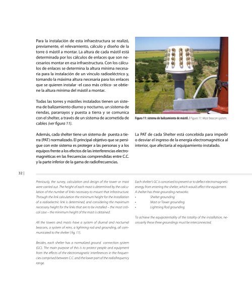
Todas las torres y mástiles instalados tienen un sistema<br />
<strong>de</strong> balizamiento diurno y nocturno, un sistema <strong>de</strong><br />
riendas, pararrayos y puesta a tierra y se comunica<br />
con el shelter, a través <strong>de</strong> un sistema <strong>de</strong> acometida <strong>de</strong><br />
cables (ver figura 11).<br />
A<strong>de</strong>más, cada shelter tiene un sistema <strong>de</strong> puesta a tierra<br />
(PAT) normalizado. El principal objetivo que se persigue<br />
con este sistema es proteger a las personas y a los<br />
equipos frente a los efectos <strong>de</strong> las interferencias electromagnéticas<br />
en las frecuencias comprendidas entre C.C.<br />
y la parte inferior <strong>de</strong> la gama <strong>de</strong> radiofrecuencias.<br />
Figura 11: sistema <strong>de</strong> balizamiento <strong>de</strong> mástil. / Figure 11: Mast beacon system.<br />
<strong>La</strong> PAT <strong>de</strong> cada Shelter está concebida para impedir<br />
o <strong>de</strong>sviar el ingreso <strong>de</strong> la energía electromagnética al<br />
interior, que afectaría al equipamiento instalado.<br />
32 |<br />
Previously, the survey, calculation and <strong>de</strong>sign of the tower or mast<br />
were carried out. The height of each mast is <strong>de</strong>termined by the calculation<br />
of the number of links necessary to mount that infrastructure.<br />
Through the link calculation the minimum height for the installation<br />
of a radioelectric link is <strong>de</strong>termined, and consi<strong>de</strong>ring the maximum<br />
necessary height for the links that are to be installed – the most critical<br />
case – the minimum height of the mast is obtained.<br />
All the towers and masts have a system of diurnal and nocturnal<br />
beacons, a system of reins, a lightning rod and grounding, all communicated<br />
to the shelter ( fig. 11).<br />
Each shelter’s GC is conceived to prevent or to <strong>de</strong>flect electromagnetic<br />
energy from entering the shelter, which would affect the equipment.<br />
A shelter has three grounding networks:<br />
• Shelter grounding<br />
• Mast or Tower grounding<br />
• Lightning Rod grounding<br />
To achieve the equipotentiality of the totality of the installation, necessarily<br />
these three groundings must be interconnected.<br />
Besi<strong>de</strong>s, each shelter has a normalized ground connection system<br />
(GC). The main purpose of this is to protect people and equipment<br />
from the effects of the electromagnetic interferences in the frequencies<br />
comprised between C.C. and the lower part of the radiofrequency<br />
range.