1 - FIBERPOOL
1 - FIBERPOOL
1 - FIBERPOOL

Create successful ePaper yourself
Turn your PDF publications into a flip-book with our unique Google optimized e-Paper software.
<strong>FIBERPOOL</strong> INTERNACIONAL<br />
TECHNICAL SERVICE: Ponent, 2-4-6<br />
P.I. Sant Pere Molanta, 08799 Olèrdola<br />
BARCELONA<br />
An authorized technician should install the control panel. The<br />
main power line must be protected by a differential and a<br />
magnetothermic. The control panel will be fixed to the wall by<br />
a screw in the upper part (as if it were an eyebolt), and two<br />
more screws through the holes situated in the inside of the<br />
connection box. The control box will be placed above the<br />
electric pump.<br />
IP 54<br />
TEMPERATURE: from 5º to 70ºC<br />
Voltage acceptable: +- 10%<br />
Feed cables and cables connecting the electric pump are to be<br />
of a 1,5mm2 wires with an insulation material of 1000v.<br />
Connections to the terminals must be made with pre-insulated<br />
connectors.<br />
The electric pump must be earthed. All site work to wire up the<br />
control panel should be done by an authorized technician,<br />
otherwise the manufacturer guarantee will not hold.<br />
WARNING: If the manufacturer uses the equipment for any<br />
purpose other than that specified, the equipment<br />
guarantees will not hold.<br />
Every 6 months, check for tightness all the connections. The<br />
installation must comply with norms of II category. The supply<br />
cables to the equipment must be installed in a way so that<br />
safety is maintained and the insulation is no subject to any<br />
damage.<br />
An anchoring device such as a packing gland must be<br />
used in order to prevent twisting and traction in the cable.<br />
FUNCTIONING<br />
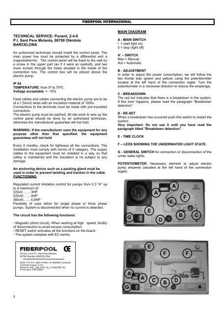
MAIN DIAGRAM<br />
A - MAIN SWITCH<br />
I = start light on)<br />
0 = stop (light off)<br />
A’ – SWITCH<br />
Man = Manual<br />
Aut = Automatic<br />
B - ADJUSTMENT<br />
In order to adjust the power consumption, we will follow the<br />
two frontal leds (green and yellow) using the potentiometer<br />
located at the left hand of the connection reglet. Turn the<br />
potentiometer in a clockwise direction to reduce the amperage.<br />
C - BREAKDOWN<br />
The red led indicates that there is a breakdown in the system.<br />
If this ever happens, please read the paragraph "Breakdown<br />
detection".<br />
D - RE-SET<br />
When a breakdown has occurred push this switch to restart the<br />
system.<br />
Very important: Do not use it until you have read the<br />
paragraph titled "Breakdown detection".<br />
E - TIME CLOCK<br />
F – LEDS SHOWING THE UNDERWATER LIGHT STATE.<br />
G - GENERAL SWITCH for connection or disconnection of the<br />
under water lights.<br />
POTENTIOMETER. Necessary element to adjust electric<br />
pump amperes (situated at the left hand of the connection<br />
reglet)<br />
Regulated current limitation control for pumps from 0,3 "A" up<br />
to a maximum of:<br />
220vII……..3HP<br />
220vIII…….4HP<br />
380vIII…….5,5HP<br />
Flexibility of uses either for single phase or three phase<br />
pumps. System is disconnected when no current is detected.<br />
The circuit has the following functions:<br />
- Magnetic (short circuit). When working at high speed, facility<br />
of disconnection to avoid excess consumption.<br />
- RESET switch activates all the functions on the board.<br />
- The system complies with EC norms.<br />
G<br />
E<br />
A’<br />
D<br />
F<br />
A<br />
B<br />
F<br />
C<br />
Ponent, 2-4-6 P.I. Sant Pere Molanta<br />
08799 Olèrdola, BARCELONA<br />
E<br />
F<br />
F<br />
MOD: P.P.A.P. 220V II7380 v III 50/60HZ Corriente<br />
Corriente equipo: 0.3 A<br />
Potencia max.: 3hp (220V II) y 5.5hp(380V III)<br />
Nº de serie: FBP-00001<br />
G<br />
A<br />
A’<br />
C<br />
B<br />
D<br />
4