BC-BCP - FIBERPOOL
BC-BCP - FIBERPOOL
BC-BCP - FIBERPOOL

Create successful ePaper yourself
Turn your PDF publications into a flip-book with our unique Google optimized e-Paper software.
YEARS OF GUARANTEE<br />
AÑOS DE GARANTIA<br />
2ANNÉES DE GARANTIE<br />
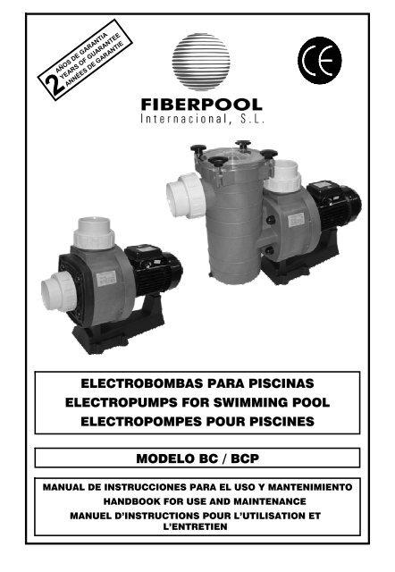
ELECTROBOMBAS PARA PISCINAS<br />
ELECTROPUMPS FOR SWIMMING POOL<br />
ELECTROPOMPES POUR PISCINES<br />
MODELO <strong>BC</strong> / <strong>BC</strong>P<br />
MANUAL DE INSTRUCCIONES PARA EL USO Y MANTENIMIENTO<br />
HANDBOOK FOR USE AND MAINTENANCE<br />
MANUEL D’INSTRUCTIONS POUR L’UTILISATION ET<br />
L’ENTRETIEN
<strong>FIBERPOOL</strong> INTERNACIONAL<br />
4- EMBALAJE, TRANSPORTE Y ALMACENAMIENTO.<br />
4.1 ATENCIÓN. El fabricante suministra el equipo protegido<br />
con el embalaje adecuado, para transportarlo, almacenarlo y<br />
que no sufra daños que impidan su correcta instalación y/o<br />
funcionamiento.<br />
4.2 ATENCIÓN. El usuario, a la recepción del equipo,<br />
comprobará inicialmente estos puntos:<br />
- Estado de embalaje exterior, si presenta signos de<br />
deterioros importantes, lo hará constar formalmente a<br />
quien se lo entrega.<br />
- Verificará también el estado del contenido; y si éste<br />
presentase desperfectos que presumiblemente<br />
impidiesen su correcto funcionamiento, lo<br />
comunicará, también formalmente, al proveedor en<br />
un plazo máximo de 8 días desde el de la recepción.<br />
4.3 ATENCIÓN. Las condiciones de almacenamiento serán<br />
tales que garanticen el buen estado de conservación del<br />
equipo. Señalamos por su especial importancia las de evitar<br />
ambientes de humedad acusada u otros donde puedan<br />
producirse cambios bruscos de temperaturas (producen<br />
condensaciones).<br />
5- INSTALACIÓN Y MONTAJE.<br />
5.1 Emplazamiento. ATENCIÓN. El lugar de instalación de la<br />
motobomba tiene que ser seco. En cualquier caso debe existir<br />
un desagüe en el suelo como protección contra inundaciones.<br />
Si se monta la bomba en un local húmedo, habrá que prever<br />
un sistema de ventilación para evitar la formación de agua de<br />
condensación. En el caso de montajes en espacios muy<br />
reducidos, el enfriamiento del aire puede ser tan bajo que sea<br />
necesario un sistema de aireación y desaireación (ventilación)<br />
con el fin de no exceder la temperatura ambiente de 40ºC<br />
(<strong>BC</strong>)-50ºC (<strong>BC</strong>P). Es importante que la reserva de espacio sea<br />
suficiente para poder desmontar el bloque motor en sentido<br />
horizontal y el filtro de cabellos en sentido vertical (véase<br />
dibujo de espacio mínimo en Fig. 1, pag. 11).<br />
5.2 Localización/ instalación. ATENCION. El equipo o<br />
conjunto del grupo motobomba, filtro y válvula selectora, se<br />
instalará cerca de la piscina a una distancia no superior a 3m<br />
de las tomas de superficie (skimmer/ rebosadero) y<br />
preferentemente a una cota de 0.5m (nunca superior a 3m)<br />
bajo el nivel del agua, para conseguir su funcionamiento “en<br />
carga”. La unión de la válvula selectora y de ésta con la<br />
boquilla y demás accesorios empotrados en la piscina se<br />
realizará prioritariamente en tubería de P.V.C. El diámetro de<br />
las tuberías dependerá de los caudales. La velocidad máxima<br />
aconsejable del agua en las tuberías ha de ser de 1.2m/s en<br />
aspiración y de 2m/s en el retorno. En cualquier caso, el<br />
diámetro de la tubería de aspiración no debe ser inferior al<br />
diámetro de la boca de la bomba. La tubería de aspiración<br />
debe ser perfectamente estanca y se ha de instalar con una<br />
pendiente descendiente (no inferior a 1/100), evitando de este<br />
modo la formación de bolsas de aire. En instalaciones<br />
permanentes, con la bomba situada en planos superiores al<br />
nivel de agua, se procurará que la tubería de aspiración en su<br />
máximo recorrido esté por debajo de los planos mencionados<br />
hasta alcanzar la vertical coincidente con el eje de aspiración<br />
de la bomba. La tubería de aspiración puede ser rígida o<br />
flexible con espiral de refuerzo que evite la contracción. En<br />
instalaciones fijas, con la bomba por debajo del nivel del agua,<br />
se colocará una válvula de cierre en aspiración y otra en<br />
impulsión.<br />
5.3 Conexión eléctrica. ATENCIÓN. Con carácter<br />
general, la instalación eléctrica estará, en todo de acuerdo con<br />
lo preescrito en los Reglamentos y Disposiciones Técnicas<br />
Complementarias que se dan a continuación y lo hará un<br />
instalador autorizado. La red de alimentación dispondrá de<br />
conductores de neutro y tierra. La tensión de la red tiene que<br />
corresponder con la dada en la placa de características del<br />
equipo. La sección de los conductores a utilizar tiene que ser<br />
suficiente para soportar, sin deterioro, la intensidad absorbida<br />
por el equipo (ver placa de características). Al conductor de<br />
tierra de la red se unirán eléctricamente todas las partes<br />
metálicas del equipo que no deben estar bajo tensión, pero<br />
que accidentalmente pudieran llegar a estarlo y sean<br />
accesibles a las personas (ver Fig.2,3,4 Págs.11-12). Es<br />
obligatoria la instalación de un cuadro eléctrico de protección y<br />
maniobra en la que se sitúan todos los elementos exigidos y<br />
otros recomendados. Con carácter general dispondrá de :<br />
a. Interruptor general de corte unipolar.<br />
b. Dispositivos de protección contra cortacircuitos y<br />
sobrecargas en los motores.<br />
c. Interruptor diferencial de alta sensibilidad, 30 mA.<br />
d. Otros, de mando y control.<br />
Las características eléctricas de los dispositivos de protección<br />
y su regulación, estarán de acuerdo con las de los motores a<br />
proteger y con las condiciones de servicio previstas por el<br />
fabricante (ver placa de características).<br />
- En equipos con motores trifásicos hay que posicionar<br />
adecuadamente los puentes de interconexiones de<br />
los devanados del motor, (ver Fig. 3,4 Pág. 12)<br />
- La entrada y salida de conductores a la caja de<br />
bornes se hará mediante prensaestopas que<br />
garantizan la ausencia de humedad y suciedad en<br />
ésta, por lo que estará provista de un cierre estanco.<br />
- Los conductores para su unión a bornes, estarán<br />
dotados de terminales adecuados.<br />
6- PUESTA EN MARCHA.<br />
Antes de poner el equipo bajo tensión, conectado a la<br />
red, se harán las siguientes operaciones:<br />
- Verificar que las condiciones eléctricas sean<br />
correctas.<br />
- Comprobar, manualmente que la motobomba no esté<br />
agarrotada.<br />
6.1 Cebado de bomba PARA BOMBAS <strong>BC</strong>. ATENCIÓN.<br />
Con la bomba por debajo del nivel del agua, llenar la bomba<br />
abriendo lentamente la válvula de cierre de aspiración,<br />
teniendo abierta la válvula situada en su impulsión.<br />
Con la bomba por encima del nivel del agua, llenar la bomba<br />
por la parte superior, abriendo la válvula de cierre de<br />
aspiración hasta haber llenado por completo tanto la tubería<br />
de aspiración como el cuerpo de bomba.<br />
6.1 Cebado de bomba PARA BOMBAS <strong>BC</strong>P. ATENCIÓN.<br />
Evitar el funcionamiento en seco de la electro bomba.<br />
Con la bomba en aspiración (por encima del nivel del agua de<br />
la piscina), antes de la puesta en marcha, retirar la tapa<br />
prefiltro bomba (pag. 17 nº16) y llenar lentamente con agua<br />
limpia hasta el nivel de la boca de aspiración. Cerrar la tapa<br />
3
<strong>FIBERPOOL</strong> INTERNACIONAL<br />
(16) de nuevo y tomar la precaución que esté herméticamente<br />
cerrada.<br />
ATENCIÓN.<br />
Con la bomba por debajo del nivel del agua de la piscina,<br />
siempre con la tapa (16) herméticamente cerrada, llenar la<br />
bomba abriendo lentamente la válvula de cierre de aspiración,<br />
teniendo abierta la válvula situada en impulsión.<br />
6.2 ATENCIÓN.<br />
Evitar el funcionamiento en seco de la electro bomba.<br />
Para mod. <strong>BC</strong>P: no se debe poner la bomba en marcha sin el<br />
cestillo (18) ya que, de esta manera, podría obstruirse y<br />
quedar bloqueada.<br />
6.3 Sentido de giro. ATENCIÓN. Asegurarse que el eje del<br />
motor gira libremente, no poner en marcha si está bloqueado.<br />
Para este fin, las electro bombas tienen una ranura en el<br />
extremo del eje, lado ventilador, que permite hacerlo girar a<br />
mano con un destornillador. Fig.1 (Pág. 11). En los motores<br />
trifásicos la turbina (pag. 16-17 nº8) pueden destornillarse si el<br />
motor arranca en sentido contrario. La rotación inversa puede<br />
también incluso dañar el sello mecánico. Arrancar pocos<br />
segundos el motor y controlar que el sentido de rotación<br />
corresponde al indicado en la flecha situada en la tapa del<br />
ventilador. Si no fuera así, es imprescindible avisar a un<br />
instalador autorizado (invertir la conexión de fases entre ellas).<br />
6.4 ATENCIÓN. Comprobar que el motor no supere el<br />
amperaje indicado en la placa de características, en caso<br />
contrario regular con la válvula situada en impulsión.<br />
Evitaremos el funcionamiento prolongado de la electro bomba:<br />
descebada, con la válvula cerrada o por falta de agua en<br />
aspiración.<br />
7. MANTENIMIENTO / CONSERVACIÓN.<br />
Antes de cualquier manipulación, desconectar la<br />
alimentación eléctrica.<br />
7.1 Modelo <strong>BC</strong>P ATENCIÓN.<br />
Controlar y limpiar periódicamente el cestillo (pag.17 nº18) de<br />
la bomba.<br />
Para extraer el cestillo situar la válvula selectora en la posición<br />
de “cerrado”, así como todas las demás válvulas del colector.<br />
Soltar la tapa (16) del prefiltro de bomba, extraer el cestillo y<br />
limpiarlo bajo un grifo de agua, no golpear para evitar su<br />
deterioro. Para ubicar nuevamente el cestillo introducirlo<br />
suavemente, hasta dejarlo en su posición primitiva. Colocar<br />
bien la junta (17) de la tapa y engrasarla con vaselina.<br />
La tapa transparente se limpiará con agua y jabón neutro; “no<br />
utilizar disolventes”. No introducir en el filtro productos<br />
químicos.<br />
No olvidar que los cambios de posición de la válvula selectora<br />
se realizan siempre con el motor parado.<br />
7.1 Modelo <strong>BC</strong>. ATENCIÓN.<br />
Si la bomba permanece parada por períodos largos, o si<br />
existiese peligro de heladas, se debe vaciar el cuerpo<br />
hidráulico (pag 16, , nº5), soltando el tapón (14) de vaciado<br />
con su junta tórica (14). Antes de poner en marcha la bomba,<br />
colocar el tapón con su tórica. Llenar de agua la bomba y<br />
comprobar con un destornillador que el motor no está<br />
bloqueado (fig 1, pag.11). Se el eje estuviese agarrotado,<br />
avisar a un técnico cualificado.<br />
En caso de inundación del motor, no intentar ponerlo en<br />
marcha, se avisará a un electrotécnico, y éste desmontará el<br />
motor para proceder al secado del mismo.<br />
7.2 ATENCIÓN. Si la bomba permanece parada por los<br />
períodos largos, o si existe peligro de heladas, se debe<br />
vaciar el cuerpo de la bomba (7,TT-5,TR), soltando los<br />
dos tapones (6) de vaciado con sus juntas tóricas . Antes<br />
de poner en marcha la bomba, colocar los tapones (6) con<br />
sus tóricas . Llenar de agua el cuerpo de bomba y<br />
comprobar con un destornillador que el motor no está<br />
bloqueado. Si el eje estuviese agarrotado, avisar a un<br />
técnico cualificado. En caso de inundación del motor, no<br />
intentar ponerlo en marcha; se avisará a un<br />
electrotécnico, y éste desmontará el motor para proceder<br />
al secado del mismo.<br />
8. DESMONTAJE<br />
8.1 ATENCIÓN. Antes de cualquier operación,<br />
todas las válvulas deben estar cerradas, comprobando esto<br />
procederemos a:<br />
-Desconectar el interruptor general eléctrico e interruptor<br />
diferencial (a realizar por especialista autorizado).<br />
Soltar y retirar los cables de alimentación de la caja de bornes<br />
-Liberar los manguitos de aspiración y retorno<br />
-Vaciar la bomba.<br />
8.2 ATENCIÓN. Para desmontar y montar la electro bomba<br />
ver plano de despiece (pag. 16-17).<br />
Para separar el motor del cuerpo hidráulico, quitaremos los<br />
seis tornillos y los dos tornillos, extraeremos el conjunto motor<br />
con la turbina (9).<br />
Para desmontar la turbina (9), quitaremos el tornillo y su junta ,<br />
utilizando la llave allen del nº8, queda de esta forma liberada<br />
la turbina (9). Al efectuar esta operación quedará también<br />
liberada la parte móvil del retén. El difusor (8) ya esta liberado.<br />
9. MONTAJE.<br />
ATENCIÓN. Todas las piezas que vayamos a acoplar<br />
deben estar limpias y en perfectas condiciones de uso.<br />
Para el montaje de la bomba procederemos:<br />
- Montar el sello mecánico (pag 16-17 nº10-11)<br />
ensamblar la parte giratoria del sello (10) sobre el<br />
saliente posterior de la turbina (13) presionando esta<br />
hasta encajar en el alojamiento, de esta forma se<br />
consigue la unión de las dos pistas del sello<br />
mecánico. Previamente habremos lubricado el retén<br />
con agua<br />
- Ensamblar la turbina (9) en el eje fijando esta<br />
mediante tornillo y su junta utilizando llave allen nº8.<br />
- En la unión de la bomba con el motor hemos de<br />
tener en cuenta que los resalte del difusor (8) encaje<br />
en el alojamiento adecuado, igualmente que las<br />
juntas (7,12).<br />
10. RECAMBIOS<br />
Para la solicitud de cualquier pieza de recambio, precisar la<br />
denominación, el número de posición en el plano de despiece<br />
(pag 16 a 23) y los datos de las placas de características<br />
1. DESCRIPTION<br />
4
<strong>FIBERPOOL</strong> INTERNACIONAL<br />
1.1 These electropumps have been designed to recirculate<br />
lightly treated water in swimming pools and spas, both private<br />
and public.<br />
1.2 Technical characteristics<br />
Motor:<br />
Power ratings: See nameplate ratings on electropump.<br />
Insulation: Class E.<br />
Operation: Continuous.<br />
Protection: IP 54.<br />
Current: Single phase and triphase (see nameplate ratings).<br />
Consumption: See nameplate ratings.<br />
Frequency: See nameplate ratings.<br />
R.P.M: See nameplate ratings.<br />
Shaft: Stainless steel.<br />
Bearing: Armoured ball bearing.<br />
Atmospheric temperature: Maximum 40ºC (<strong>BC</strong>) 50ºC (<strong>BC</strong>P).<br />
Pump:<br />
Water temperature: Max 50ºC<br />
Maximum pressure: 2 BARS<br />
Impeller model: Closed<br />
Type of seal: Mechanical retainer.<br />
Diffuser : Synthetic material (PP)<br />
Impeller : Noryl with Fiber Glass<br />
Pump Casing : Synthetic material (PP)<br />
Filter lid for <strong>BC</strong>P model : Synthetic material<br />
Aspiration diameter : Socket 90mm<br />
Impelling diameter : Socket 90mm<br />
2. GENERAL<br />
2.1 Introduction<br />
This handbook contains the necessary instructions for<br />
installation, use and maintenance of the swimming pool<br />
electropump. In order to obtain the maximum yield shown by<br />
the manufacturer in the Description of Characteristics, it is<br />
necessary to fulfil and follow correctly all the recommendations<br />
given in this-Handbook. This will allow operation with a safe<br />
and long-lasting piece of equipment. The equipment supplier<br />
will furnish the user with complementary information, if<br />
required.<br />
2.2-Safety signs used in the handbook.<br />
All instructions referring to possible risks to persons are<br />
highlighted by the followings symbols:<br />
Standard DIN 4844-W9<br />
Danger in general<br />
Standard DIN 4844-W8<br />
Danger of electrocution.<br />
Other instructions in relation to the functioning of the<br />
equipment with which non-compliance could cause physical<br />
damages are highlighted with the warning: ATTENTION<br />
2.3 Nameplate ratings (EEC 89/392 P.1.7.4.A.) The<br />
information given on the nameplate or other instructions affixed<br />
by the manufacturer to the unit, must be strictly complied with.<br />
The content of these plates can usually be found in this<br />
Handbook (Chapter 1.2).<br />
2.4 Liability. Failure to comply with the instructions given by<br />
manufacturer in this handbook, in relation to the choice,<br />
handling, installation, starting and maintenance of the unit,<br />
shall release the manufacturer or distributor from all liability in<br />
respect of accidents suffered by persons or damages caused<br />
to other installations and, in addition, shall entail forfait of the<br />
warranty.<br />
2.5 Standard. Our swimming pool electropumps are<br />
manufactured in accordance with the necessary requirements<br />
for safety and health set forth in Community Directives<br />
89/392/EEC, 91/368/EEC (assimilated into Spanish Law by<br />
Royal Decrees, 1435/1992 and 93/44/EEC).<br />
3 GENERAL INSTRUCTIONS IN RELATION TO USER<br />
SAFETY.<br />
3.1 Safety during operation of the machinery supplied<br />
can only be guaranteed if it is used in accordance with the<br />
diagrams show n on page 11-12 “Illustrations”. It must never<br />
exceed the working conditions and limits given in this<br />
Handbook (chapter 1.2 – Technical Characteristics).<br />
Compliance with the provisions of Safety Standards in force in<br />
each country is mandatory.<br />
3.2 Please ensure that the equipment selected is<br />
adequate for the use for which it is intended and that its<br />
condition, installation, starting and subsequent use are correct.<br />
See chapter 1 (Technical Characteristics).<br />
3.3 Installation, repair and maintenance operations will<br />
be carried out in all cases with equipment disconnected from<br />
the mains.<br />
3.4 While the equipment is functioning, it cannot be<br />
moved or repositioned. These operations will be carried out at<br />
all times with the machine disconnected.<br />
3.5 Pressing of the electrical on/off or safety elements<br />
will not be performed where there is damp, and special care<br />
must be taken for user’s hands to be dry, and also with<br />
footwear and surfaces with which the user is in contact.<br />
3.6 Those elements of the equipment which, when<br />
functioning, are in movement or which could reach dangerous<br />
temperatures, will be protected with cages or casings which<br />
will prevent accidental contact with the same.<br />
3.7 Electricity conductors, or parts which could carry<br />
current, will be suitably insulated. Other metal parts of the<br />
equipment will be correctly earthen.<br />
3.8 Spare parts that may be necessary will be originals<br />
from the manufacturer or those recommended by the<br />
manufacturer. The use of others, or originals rectified by<br />
others, are not permitted and release the manufacturer or<br />
distributor from all liability.<br />
4 PACKING, TRANSPORT AND STORAGE<br />
4.1 ATTENTION. The manufactured supplies the equipment<br />
protected in suitable packaging, so that it is not damaged<br />
during transport or storage thus preventing its correct<br />
installation and/or functioning.<br />
5
<strong>FIBERPOOL</strong> INTERNACIONAL<br />
4.2 ATTENTION. The user, upon receipt of the equipment, will<br />
immediately check the following points:<br />
- Condition of the outside packaging, if this shows<br />
signs of serious deterioration, he shall formally advise<br />
the person delivering the equipment.<br />
- He shall also check the condition of the contents:<br />
should this show defects which would presumably<br />
prevent correct functioning, he shall also formally<br />
notify the supplier within a period not exceeding 8<br />
days from the date of delivery.<br />
4.3 ATTENTION. Storage conditions must ensure the optimum<br />
preservation of the equipment. Due to its particular relevance,<br />
we must stress that very damp atmosphere or others where<br />
brusque changes in temperatures (which cause condensation)<br />
must be avoided.<br />
5. INSTALLATION AND ASSEMBLY<br />
5.1 Location. ATTENTION. The place where the electropump<br />
is to be located must be dry. In all events, there must be a<br />
drain in the floor as prevention against flooding. If the pump is<br />
to be located in a damp place, a ventilation system must be<br />
provided in order to prevent the formation of condensation. In<br />
the case of very confined areas, cold air can reach a low<br />
temperature which requires a ventilation system where by the<br />
atmospheric temperature does not exceed 40ºC. (<strong>BC</strong>) –<br />
50ºC.(<strong>BC</strong>P). It's important for there to be sufficient space to<br />
permit the motor block to be dismounted horizontally and the<br />
hair filter vertically (see minimum space diagram in fig. 1, page<br />
11.<br />
5.2 Positioning /installation<br />
ATTENTION. The equipment or set of motor pump, filter and<br />
selection valve, will be installed near the swimming pool at a<br />
distance of no more than 3 m, from the surface skimmers and<br />
preferably at the level of 0.5m (never more that 3m) below the<br />
level of the water in order to achieve its “under load”<br />
functioning. The selection valve junction, and its connection to<br />
the nozzle and other accessories incorporated in the swimming<br />
pool will preferably be made in PVC casing. Pipe diameters will<br />
depend on flows. The maximum water speed advisable in the<br />
pipes will be 1.2 m/s in aspiration and 2 m/s on return. In any<br />
event, the diameter of the aspiration of the aspiration pipe<br />
must not be less than diameter of the pump nozzle. The<br />
aspiration pipe must be perfectly watertight and must be<br />
installed with a downward inclination, thus avoiding the<br />
formation of air pockets. In permanent installations, with the<br />
pump positioned at a higher level than that of the water, it is<br />
advisable for the longest stretch of the aspiration pipe to be<br />
below the plans mentioned until it reaches the vertical pipe<br />
which coincides with the pump aspiration shaft. The aspiration<br />
pipe can be either rigid or flexible with a reinforced coil to avoid<br />
contraction.<br />
In fixed installations, with the pump below the water level, a<br />
shut-off valve will be placed on the aspiration pipe and another<br />
on the header pipe.<br />
ATTENTION. When using as a portable pump,<br />
suitable electrical protection must be provide and the pump<br />
must be assembled on an insulated base.<br />
5.3 Connections to the mains.<br />
ATTENTION. In general terms, the electrical installation will<br />
fully comply with the Regulations and Complementary<br />
Technical provisions applicable and will be performed by an<br />
authorised Installer. The supply will have neutral and earth<br />
wires. The mains voltage must correspond to that shown on<br />
the nameplate rating for the equipment. the earth wire to be<br />
used must be sufficient to take, without deterioration, the<br />
current absorbed by the equipment (see nameplate). The<br />
mains earth wire will be connected electrically to all metal parts<br />
of the equipment which should not be under current, but which<br />
could accidentally be affected by the same and which are<br />
accessible to persons (see figs. 2,3,4 pag. 11-12).<br />
It is obligatory to install a protection and operation switchboard,<br />
which will contain all necessary and recommended elements.<br />
In general terms, it will contain:<br />
a. General cut-off or unipolar switch.<br />
b. Short-circuit and overload protection devices for<br />
motors.<br />
c. 30mA differential high sensitivity switch.<br />
d. Others for monitoring and control.<br />
The electrical characteristics of the protection devices and their<br />
regulation will comply with those for these, and the instructions<br />
given by the manufactured must be (see nameplate).<br />
- In the case of equipment with triphase motors, the<br />
motor winding interconnection bridges must be<br />
suitably positioned (see figs 3-4, page 12).<br />
- Conductor inlets and outlets at the bushing box will<br />
have stuffing to ensure the absence of damp and dirt,<br />
and will therefore have a sealed casing.<br />
- Conductors will have suitable terminals for connection<br />
to the bushings.<br />
6. STARTING<br />
Before connecting the equipment to the Mains, the<br />
following operations will be carried out:<br />
- Check that the electrical conditions are correct.<br />
- Manually check that the motor pumps not jammed.<br />
6.1 Pump priming for <strong>BC</strong> models: With the pump placed<br />
under the water level, fill the pump opening slowly the<br />
aspiration valve, maintaining open the valve at the impelling<br />
side.<br />
With the pump above the water level, fill the pump by the<br />
upper part, opening the aspiration valve, until the aspiration<br />
pipe and body pump will be completely full.<br />
6.1. Pump priming for <strong>BC</strong>P models: Avoid blind functioning<br />
of the electropump. With the pump in the aspiration position<br />
(placed above the water level) before starting, remove the<br />
prefilter cover (pag17 nº16) and slowly fill it with clean water up<br />
to the level of the aspiration valve. Close the cover again and<br />
take are that it is hermetically closed.<br />
ATTENTION<br />
With the pump below the water level and always with the lid<br />
(16) hermetically closed, fill the pump by slowly opening the<br />
aspiration cut-off valve, with the header valve in the open<br />
position.<br />
6.2 ATTENTION<br />
Avoid blind functioning of the electro-pump.<br />
For <strong>BC</strong>P model, the pump must not be started without the<br />
basket hair filter inside (18) otherwise it could cause<br />
obstruction and block the system.<br />
6
<strong>FIBERPOOL</strong> INTERNACIONAL<br />
6.3 Direction of rotation. ATTENTION.<br />
Ensure that the motor shaft turns freely; do not start the pump<br />
if is blocked. For this purpose, electropumps have a groove at<br />
the end of the shaft, on the ventilator side, which permits it to<br />
be turned manually using a screwdriver (fig 1 page 11 ).<br />
In triphase motors, the impeller, (pag.16-17 nº8) can be<br />
unscrewed if the motors starts in the opposite direction.<br />
Counter-rotation can even damage the mechanical seal. Start<br />
the motor for a few seconds and check that the direction of<br />
rotation coincides with that indicated by the arrow on the<br />
ventilator cover. Should this not be the case, it is absolutely<br />
necessary to advise the authorised installer (invert the phase<br />
connection).<br />
6.4 ATTENTION.<br />
Check that motor does not exceed the amperage indicate on<br />
the nameplate rating other wise, regulate using the header<br />
valve.<br />
7- MAINTENANCE / CONSERVATION<br />
Before touching, disconnect the electricity supply.<br />
7.1 <strong>BC</strong>P model – ATTENTION -<br />
Check and clean the filter basket regularly (pag.17 Nº18 )<br />
To remove the prefilter place the selection valve as well as all<br />
other valves in the closed position. Take out the prefilter cover<br />
(17) remove the basket and clean it under running water. To<br />
avoid any deterioration, do not strike it. To replace the prefilter<br />
basket introduce it until its original position. Place the seal (17)<br />
on the cover and grease it with Vaseline. The transparent<br />
cover must be cleaned with water and neutral soap. "Do not<br />
use solvents and do not introduce chemical products inside".<br />
7.1 <strong>BC</strong> model – ATTENTION –<br />
If the pump is switched off during a long period of time or<br />
should there be any danger of frost, the hydraulic casing (page<br />
16 Nº5) must be emptied, by loosening the outlet together with<br />
its o'ring seal (14). Before starting the pump fit the outlet and<br />
its o'ring seal. Fill the pump with water and check it with a<br />
screwdriver that the motor is not jammed. (Fig.1 Pag.11), If the<br />
shaft has seized up, call a qualified technician. In case of the<br />
motor flooding, do not start it. Call an electrician who will<br />
dismantle the motor in order to dry it.<br />
8.DISMOUNTING<br />
8.1 ATTENTION. Before performing any<br />
operation, all valves must be in the “off” position: having<br />
checked this:<br />
- Disconnect the general electricity switch and the<br />
differential switch (this must be done by an authorized<br />
specialist)<br />
- Loosen and remove the supply cables on the<br />
bushings box (40, mod TT) (29, mod TR).<br />
- Release the aspiration and return sleeves.<br />
- Empty the pump.<br />
8.2. ATTENTION - To dismantle and assemble the<br />
electropump, see detail drawing (pag.16-17). To remove the<br />
motor from the hydraulic casing, remove the six screws and<br />
the two screws, and take out the motor set with the impeller<br />
(9).<br />
In order to dismantle the impeller (9) we will remove the screw<br />
and its o-ring using an Allen key Nº 8, this way the impeller (9)<br />
will be loose. By doing this operation the mechanical seal will<br />
be loose as well as the diffuser (8).<br />
9-ASSEMPLY<br />
ATTENTION.<br />
“All parts to be assembled must be clean and in perfect<br />
condition for use”.<br />
- Assemble the mechanical seal (pag. 16-17 nº10-11);<br />
assemble the rotary part of the seal (10) above the back flange<br />
of the impeller (9) by pressing until this falls into the space. By<br />
this way we will obtain the union of the two parts of the seal.<br />
The retainer has been previously lubricated with water.<br />
- Assemble the impeller (9) on the shaft fixed by a screw using<br />
an Allen key Nº 8.<br />
- We have to take in mind that the diffuser (8) flange as well as<br />
the seals (7,12) must be fit into the correct space at the point<br />
of union between the pump and the motor.<br />
10 – SPARE PARTS<br />
To order any spare parts, indications must be given of the<br />
denomination, number shown on the detail drawing (pages16<br />
to 23) and nameplate.<br />
7.2 ATTENTION. If the pump is switched off for long periods<br />
of time, should there be a danger of frost, the pump casing<br />
(pag.16-17 nº5) should be emptied, by loosening the two<br />
emptying outlets (14) along with their O-ring seals.<br />
Before starting the pump, replace the outlets (14) and their O-<br />
ring seals. Fill the pump chamber with water and check with a<br />
screwdriver that the motor is not jammed. If the shaft has<br />
seized up, call a qualified technician. In the event of the motor<br />
flooding, do not try to start it; call an electrician to dismount the<br />
motor in order to the dry it.<br />
7
<strong>FIBERPOOL</strong> INTERNACIONAL<br />
1 - DESCRIPTION<br />
1.1 Ces électropompes ont été conçues pour réaliser la<br />
recirculation des eaux légèrement traitées pour piscines et<br />
spas, aussi bien privées que publiques.<br />
1.2 Caractéristiques techniques<br />
Moteur :<br />
Puissance : Voir plaque d’électropompe.<br />
Isolement : Classe F.<br />
Service : Continu.<br />
Protection : IP 54<br />
Tension : Monophasée et triphasée (voir plaque de<br />
caractéristiques).<br />
Consommation : Voir plaque de caractéristiques.<br />
Fréquence : Voir plaque de caractéristiques.<br />
Axe : Acier inox.<br />
Palier : Roulement à billes blindé.<br />
Température ambiante : Maximum 40ºC. (<strong>BC</strong>) 50ºc.(<strong>BC</strong>P).<br />
Pompe :<br />
Température eau : Maximum 50ºC.<br />
Pression maximale : 2 bars.<br />
Modèle turbine: Fermée.<br />
Type de scellement : Renfort mécanique.<br />
Diffuseur : Matériel synthétique (PP)<br />
Turbine : NORYL avec fibres de verre<br />
Corps de pompe : Matériel synthétique (PP)<br />
Couvercle du modèle <strong>BC</strong>P : Matériel synthétique (SAM)<br />
Panier du modèle <strong>BC</strong>P : Matériel synthétique (PP)<br />
Diamètre d'aspiration : Coller 90mm<br />
Diamètre de refoulement : Coller 90mm<br />
2 - GENERALITES<br />
2.1 Introduction. Ce manuel comprend les instructions<br />
nécessaires pour l’installation, l’utilisation et l’entretien de<br />
l’électropompe de piscines. Pour atteindre les performances<br />
que le fabricant indique sur le Cahier de Caractéristiques il<br />
faut suivre correctement toutes les recommandations<br />
indiquées dans ce manuel. Cela permettra de travailler avec<br />
un équipement sûr et durable. Le fournisseur de l’équipement<br />
donnera à l’utilisateur l’information supplémentaire si celui-ci le<br />
lui demande.<br />
2.2 Symboles de sécurité dans le manuel d’instructions.<br />
Les instructions qui ont trait aux risques pour les personnes<br />
sont représentées au moyen des deux symboles suivants :<br />
Norme DIN 4844-W9<br />
Précaution pour danger en général<br />
Norme DIN 4844-W8<br />
Précaution pour danger de décharge<br />
électrique<br />
D’autres instructions en rapport avec le fonctionnement de<br />
l’équipement et dont le manque d’accomplissement peut<br />
l’abîmer physiquement, sont distinguées avec l’inscription :<br />
ATTENTION<br />
2.3 Plaques de caractéristiques (CEE 89/392 p.1.7.4.a)<br />
Tout ce qui est indiqué sur la plaque de caractéristiques ou<br />
d’autres instructions que le fabricant place sur l’unité seront<br />
exactement suivies. Le contenu de ces plaques sera<br />
normalement compris dans ce manuel (Chapitre 1.2).<br />
2.4 Responsabilité. Le manque d’accomplissement des<br />
instructions indiquées par le fabricant dans ce manuel, pour<br />
l'élection, l'utilisation, l'installation, la mise en marche et<br />
l'entretien de l’unité, exonère le fabricant ou le distributeur de<br />
responsabilités par accident possibles sur les personnes ou<br />
dommages sur le reste des installations, et entraînera, d’autre<br />
part, la perte de garantie.<br />
2.5 Normes. Les électropompes de piscines de notre marque<br />
sont fabriquées conformément aux conditions essentielles de<br />
sécurité et santé établies par les Directives communautaires<br />
89/392/CEE, 91/368/CEE (transposés au droit espagnol dans<br />
le Décret Royal 1435/1992 et 93/44/CEE)<br />
3 - INSTRUCTIONS GENERALES CONCERNANT LA<br />
SÉCURITÉ DE L’UTILISATEUR<br />
3.1 La sécurité du fonctionnement de la machine<br />
fournie ne pourra être assurée que si son utilisation répond à<br />
ce qui est indiqué sur les figures de la page 11-12<br />
illustrations". Les conditions et les limites de travail indiquées<br />
dans ce manuel ne devront jamais être dépassés(chapitre 1.2<br />
–Caractéristiques Techniques). Il est obligatoire de respecter<br />
les Normes de Sécurité en vigueur dans chaque pays.<br />
3.2 Vérifer que l’équipement a été correctement<br />
sélectionné pour l’application à laquelle li sera destiné et que<br />
sont état, installation, mise en marche et sont ultérieure<br />
utilisation sont corrects. Voir chapitre 1.2 (Caractéristiques)<br />
3.3 Les opérations d’installation, réparation et entretien<br />
seront toujours réalisées avec l’équipement débranché du<br />
réseau d’alimentation électrique.<br />
3.4 Lors du fonctionnement de l’équipement il ne peut<br />
être déplacé ni sa position corrigée. Ces opérations seront<br />
toujours réalisées avec la machine arrêtée.<br />
3.5 L’actionnement des éléments électriques de<br />
connexion -déconnexion ou sécurité ne peut pas avoir lieu en<br />
présence d’humidité, tout en faisant une spéciale attention à<br />
l'humidité qui peut exister sur les mains de l’ouvrier, ses<br />
chaussures ou les surfaces de contact.<br />
3.6 Les éléments de l’équipement qui lors de leur<br />
fonctionnement sont en mouvement ou puissent atteindre des<br />
températures dangereuses seront protégés au moyen de<br />
petites grilles ou armatures qui empêchent le contact<br />
accidentel avec eux.<br />
3.7 Les conducteurs électriques, ou les parties qui<br />
peuvent être sous tension, auront un isolement approprié.<br />
D’autres parties métalliques de l’équipement seront<br />
solidairement raccordées à terre.<br />
3.8 Les pièces de rechange seront les originaires du<br />
fabricant ou les préconisés par celui-ci. L’utilisation d’autres<br />
pièces ou des pièces d'origines rectifiées par des tiers n’est<br />
pas admise et libère le fabricant ou le distributeur de leurs<br />
responsabilités.<br />
4- EMBALLAGE, TRANSPORT ET STOCKAGE<br />
4.1 ATTENTION. Le fabricant fournit l’équipement protégé<br />
avec l’emballage approprié afin que lors du transport ou<br />
stockage il ne subisse pas de dommages qui empêchent sa<br />
correcte installation et/ou fonctionnement.<br />
8
<strong>FIBERPOOL</strong> INTERNACIONAL<br />
4.2 ATTENTION. L’utilisateur, à la réception de l’équipement,<br />
vérifiera les points suivants :<br />
-Etat de l’emballage extérieur ; s’il présente des signes de<br />
dégradation importants, il le communiquera formellement à<br />
celui qui le lui a fournit.<br />
-Il vérifiera aussi l’état du contenu ; si celui-ci présente des<br />
dommages qui pourraient empêcher probablement son<br />
fonctionnement correct, il le communiquera formellement au<br />
fournisseur dans un délai maximum de 8 jours dès la date de<br />
réception.<br />
4.3 ATTENTION. Les conditions de stockage devront assurer<br />
le bon état de conservation de l’équipement. Il est important de<br />
remarquer d’éviter des environnements humides élevés ou<br />
d’autres qui pourraient produire des changements brusques de<br />
températures (ils produisent des condensations).<br />
5 - INSTALLATION ET MONTAGE<br />
5.1 Emplacement. ATTENTION. L’endroit d’installation de la<br />
motopompe doit être sec. Dans tous les cas il doit exister un<br />
écoulement au sol comme protection contre les inondations. Si<br />
la motopompe est installée dans un local humide, il y aura lieu<br />
de prévoir un système d’aération afin d’éviter la formation<br />
d’eau de condensation. Dans le cas de montages dans des<br />
espaces très réduits, le refroidissement de l’air peut être<br />
tellement bas qu’il soit nécessaire un système d’aération et de<br />
(ventilation) afin que la température ambiante n’excède pas<br />
40ºC.(<strong>BC</strong>) – 50º(<strong>BC</strong>P). Il est important que la réserve d’espace<br />
soit suffisante pour pouvoir démonter le bloc-moteur à<br />
l’horizontale et le filtre à cheveux à la verticale (voir dessin<br />
d’espace minimum en fig. 1, page 11.<br />
5.2 Positionnement / Installation<br />
ATTENTION. L’équipement ou l’ensemble du groupe<br />
motopompe, filtre et vanne de sélection sera installé près de la<br />
piscine à une distance non supérieure de 3 m des prises de<br />
surface (skimmer/débordement) et préférablement à une cote<br />
de 0.5m (jamais supérieur à 3m) sous le niveau de l’eau, pour<br />
son fonctionnement « en charge ». La liaison de la vanne de<br />
sélection et de celle-ci avec le raccord et d’autres accessoires<br />
scellés dans la piscine sera réalisée préférablement en tuyau<br />
de PVC. Le diamètre des tuyaux dépendra des débits. La<br />
vitesse maximale recommandée de l’eau dans les tuyaux doit<br />
être de 1.2 m/s en aspiration et 2 m/s en retour. En tout cas, le<br />
diamètre du tuyau d’aspiration ne doit pas être inférieur au<br />
diamètre de la bouche de la pompe. Le tuyau d’aspiration doit<br />
être parfaitement étanche et être placé sur une pente<br />
descendante, pour éviter la formation de trous d’air.<br />
Pour les installations permanentes, avec la pompe placée sur<br />
de plans supérieurs au niveau de l’eau, on veillera à ce que le<br />
tuyau d’aspiration au maximum de son parcours soit audessous<br />
des plans mentionnés jusqu’à atteindre la verticale<br />
qui coïncide avec l’axe d’aspiration de la pompe. Le tuyau<br />
d’aspiration peut être rigide ou flexible avec spirale de<br />
renforcement qui évite la contraction. Pour les installations<br />
fixes, avec la pompe au-dessous du niveau de l’eau, on<br />
placera une vanne de fermeture en aspiration et une autre en<br />
impulsion.<br />
ATTENTION. Pour son utilisation comme pompe<br />
portative, il faudra envisager une protection appropriée<br />
électrique et démonter la pompe sur une base isolante.<br />
5.3 Connexion électrique. ATTENTION. En<br />
général, l’installation électrique respectera tout ce qui est établi<br />
par les Règlements et Dispositions Techniques<br />
Supplémentaires qui soient applicables et sera réalisée par un<br />
installateur autorisé. Le réseau d’alimentation aura des<br />
conducteurs de neutre et terre. La tension du réseau doit<br />
correspondre avec celle qui est donnée sur la plaque de<br />
caractéristiques de l’équipement.<br />
La section des conducteurs à utiliser doit être suffisante pour<br />
supporter, sans dommages, celle de l’intensité absorbée par<br />
l’équipement (voir plaque de caractéristiques).<br />
Au conducteur de terre du réseau seront liées électriquement<br />
toutes les parties métalliques de l’équipement qui ne doivent<br />
pas être sous tension mais qu'elles puissent l'être<br />
accidentellement ou accessibles pour les personnes (voir figs.<br />
2,3,4 pages 11-12)<br />
L’installation d’un coffret électrique de protection et manœuvre<br />
sera obligatoire. Dans celui-ci seront situés tous les éléments<br />
rigides et d’autres recommandés. En général, il sera composé<br />
de :<br />
a. Interrupteur général de coupure ou unipolaire.<br />
b. Dispositifs de protection contre court-circuits ou<br />
surcharges sur les moteurs.<br />
c. Interrupteur différentiel à haute sensibilité, 30 mA.<br />
d. D’autres, de commande et contrôle.<br />
Les caractéristiques électriques des dispositifs de protection et<br />
leur régulation seront conformes à celles des moteurs à<br />
protéger et aux conditions de fonctionnement prévues pour<br />
ceux-ci et suivront les instructions du fabricant (voir plaque de<br />
caractéristiques).<br />
- Sur les équipements avec moteurs triphasés il faut<br />
positionner de manière appropriée les ponts<br />
d’interconnexions des bobinages du moteur (voir figs.<br />
3-4 page 12).<br />
- L’entrée et sortie des conducteurs à la boîte de<br />
bornes aura lieu au moyen de presse-étoupes qui<br />
assurent l’absence d’humidité et saleté dans celle-ci,<br />
donc, une fermeture étanche sera envisagée.<br />
- Les conducteurs, pour leur liaison aux bornes, seront<br />
munis de terminaux appropriés.<br />
6 – MISE EN MARCHE<br />
Avant de mettre l’équipement sous tension, raccordé au<br />
réseau, réaliser les suivantes opérations :<br />
- Vérifier que les conditions électriques sont correctes.<br />
- Vérifier manuellement, que la motopompe n’est pas<br />
grippée.<br />
6.1 Charge de la pompe. POUR MODELES <strong>BC</strong>.<br />
ATTENTION.<br />
Avec la pompe au-dessous du niveau de l'eau de la piscine,<br />
remplir la pompe tout en ouvrant lentement la vanne de<br />
fermeture d'aspiration, laissant ouverte la vanne située à<br />
l'impulsion.<br />
Avec la pompe au-dessus du niveau de l'eau, remplir la pompe<br />
par la partie supérieure, tout en ouvrant la vanne de fermeture<br />
d'aspiration jusqu'au remplissage complet aussi bien du<br />
conduit d'aspiration que du corps de la pompe.<br />
6.1 Charge de la pompe. POUR MODELES <strong>BC</strong>P.<br />
ATTENTION<br />
Eviter le fonctionnement à sec de l'electro-pompe.<br />
Avec la pompe en aspiration (au-dessus du niveau de l'eau de<br />
la piscine) et avant la mise en marche, retirer le couvercle du<br />
prefiltre de la pompe (16) et remplir lentement avec de l'eau<br />
propre jusqu'au niveau de la buse d'aspiration. Fermer à<br />
nouveau le couvercle (16) et prendre soin à ce qu'il soit<br />
hermétiquement fermé.<br />
9
<strong>FIBERPOOL</strong> INTERNACIONAL<br />
ATTENTION.<br />
Avec la pompe au-dessous du niveau de l'eau de la piscine, et<br />
toujours avec le couvercle (16) hermétiquement fermé, remplir<br />
la pompe en ouvrant lentement la vanne de fermeture<br />
d'aspiration et en ayant ouverte la vanne située en impulsion.<br />
6.2 ATTENTION<br />
Eviter le fonctionnement à sec de l'électro-pompe.<br />
Pour le modèle <strong>BC</strong>P : Ne pas mettre la pompe en marche<br />
sans le panier (18) car autrement la pompe pourrait s'obstruer<br />
et rester bloquée.<br />
6.3 Sens du tour. ATTENTION. Vérifier que l’axe du moteur<br />
tourne librement, ne pas les mettre en arche s’il est bloqué. A<br />
cet effet, les électropompes ont une rainure au bout de l’axe,<br />
du côté du ventilateur, qui permet de la faire tourner à la main<br />
en se servant d’un tournevis (fig. 1 page 11)<br />
Pour les moteurs triphasés, la turbine (pag.16-17 nº8) peut<br />
être devisée si le moteur démarre en sens contraire. La<br />
rotation inverse peut aussi abîmer le scellement mécanique.<br />
Faire démarrer peu de secondes le moteur et contrôler que le<br />
sens de rotation correspond à celui indiqué par la flèche située<br />
sur le couvercle du ventilateur. Au cas où ce ne serait pas<br />
ainsi, il faut faire appel à un installateur autorisé (invertir la<br />
connexion de phases entre elles).<br />
6.4 ATTENTION. Vérifiez que le moteur ne dépasse pas<br />
l’ampérage indiqué sur la plaque de caractéristiques<br />
Autrement, régler avec la vanne située à l’impulsion.<br />
On évitera le fonctionnement prolongé de l’électropompe : non<br />
chargée, avec une vanne fermée ou faute de l’eau<br />
d’aspiration.<br />
7 ENTRETIEN / CONSERVATION<br />
Avant toute manipulation, déconnecter l’alimentation<br />
électrique.<br />
7.1 Modèle <strong>BC</strong>P - ATTENTION<br />
Contrôler et nettoyer quotidiennement le panier (pag.17 nº18)<br />
de la pompe. Pour extraire le panier, placer la vanne de<br />
sélection en position "fermée", ainsi que toutes les autres<br />
vannes du collecteur. Lâcher le couvercle (16) du prefiltre de la<br />
pompe, ôter le panier et le nettoyer sous le robinet d'eau, ne<br />
pas le taper afin d'éviter de l'endommager. Afin de replacer à<br />
nouveau le panier l'introduire lentement jusqu'à le laisser dans<br />
sa position d'origine. Placer soigneusement le joint du<br />
couvercle (17) et le graisser avec de la vaseline.<br />
Le couvercle transparent devra être nettoyé avec de l'eau et<br />
du savon neutre, Ne pas utilisé de dissolvants". Ne pas<br />
introduire de produits chimiques dans le filtre.<br />
Ne pas oublier que les changements de position de la vanne<br />
de sélection se réaliseront toujours avec le moteur arrêté.<br />
7.1 Modèle <strong>BC</strong> – ATTENTION<br />
Si la pompe est arrêtée pendant une longue période ou bien<br />
s'il existe une possibilité de gelée, on doit vider le corps<br />
hydraulique (pag.16 nº5) en lâchant le bouchon de vidange<br />
(14) et le joint torique. Avant de mettre en marche la pompe,<br />
placer le bouchon avec son joint (14). Remplire la pompe<br />
avec de l'eau et vérifier avec un tournevis que le moteur n'est<br />
pas bloqué (Fig.1 Pag.11). Si l'axe est grippé prévenir un<br />
technicien qualifié.<br />
En cas d'inondation du moteur, ne pas le mettre en marche,<br />
faire appel à un electro-technicien qui démontera le moteur et<br />
procédera à son séchage.<br />
7.2 ATTENTION. Si la pompe est arrêtée pour de longs<br />
délais ou s’il existe possibilité de gelée, le corps de la pompe<br />
(pag.16-17 nº5) doit être vidé, en lâchant les deux bouchons<br />
de vidange (14) avec leurs joints toriques.<br />
Avant de mettre en marche la pompe, placer les bouchons<br />
(14) avec ses toriques. Remplir d’eau le corps de la pompe et<br />
vérifier avec un tournevis que le moteur n’est pas bloqué. Si<br />
l’axe était grippé, faire appel à un technicien qualifié. En cas<br />
d’inondation du moteur, ne pas essayer de la mettre en<br />
marche ; faire appel à un électrotechnicien et celui-ci<br />
démontera le moteur pour le sécher.<br />
8. DEMONTAGE<br />
8.1 ATTENTION. Avant toute opération, toutes<br />
les vannes doivent être fermées. Après avoir vérifier cela :<br />
- Déconnecter l'interrupteur général électrique et<br />
l'interrupteur différentiel (à réaliser par un spécialiste<br />
autorisé).<br />
- Lâcher et retirer les câbles d’alimentation de la boîte<br />
de bornes<br />
- Libérer les douilles d’aspiration et retour.<br />
- Vider la pompe.<br />
8.2 ATTENTION. Pour démonter et monter l'électro pompe<br />
voir le plan de la vue éclatée (pag.16-17)<br />
Pour séparer le moteur du corps hydraulique, ôter les 6 visses<br />
et les 2 visses et extraire l'ensemble du moteur avec la turbine<br />
(9).<br />
Pour démonter la turbine (9), ôter la vis et le joint en utilisant<br />
une clé Allen Nº 8, de cette façon la turbine (9) restera lâchée.<br />
Quand cette opération sera effectuée la partie mobile du joint<br />
d'étanchéité sera également libéré ainsi que le diffuseur (8).<br />
9– MONTAGE<br />
ATTENTION.<br />
« Toutes les pièces à assembler seront propres et en<br />
parfaites conditions d’utilisation ».<br />
Pour le montage de la pompe :<br />
- Monter le scellement mécanique (pag 16-17 nº10-11),<br />
assembler la partie tournante du scellement (10) sur le saillant<br />
postérieur de la turbine (9) tout en poussant celle-ci jusqu'à<br />
l'encastrer dans le logement. De cette façon on obtient l'union<br />
des deux parties du scellement mécanique. Préalablement<br />
nous aurons lubrifié la bague avec de l'eau.<br />
- Assembler la turbine (9) dans l'axe, fixant celle-ci à l'aide<br />
d'une vis et son joint en utilisant une clé Allen Nº 8.<br />
- Lors de l'union de la pompe avec le moteur on doit tenir<br />
compte que la saillie du diffuseur s'emboîte dans le logement<br />
approprié et de même pour les joints (7-12).<br />
10 – PIÈCES DÉTACHÉES<br />
Pour commander des pièces de rechange, préciser la<br />
dénomination, le numéro de position sur l'éclaté de démontage<br />
(pag 16 a 23) et les données des plaques de caractéristiques.<br />
10
<strong>FIBERPOOL</strong> INTERNACIONAL<br />
1 – DESCRIPCIÓN<br />
1.1 Estas electro bombas han sido diseñadas para efectuar la<br />
recirculación de aguas ligeramente tratadas en piscinas y<br />
spas, privadas y publicas.<br />
1.2 Características técnicas<br />
-Motor:<br />
Potencia: Ver placa de la electro bomba.<br />
Aislamiento: Clase F.<br />
Servicio: Continuo.<br />
Protección: IP 54<br />
Tensión: Monofásica y trifásica (ver placa de características)<br />
Consumo: Ver placa de características.<br />
Frecuencia: Ver placa de características.<br />
R.P.M : Ver placa de características.<br />
Eje: Acero inoxidable.<br />
Cojinete: Rodamiento de bolas blindado.<br />
Temperatura ambiente: Máximo 40ºC.(<strong>BC</strong>) 50ºC.(<strong>BC</strong>P).<br />
-Bomba:<br />
Temperatura agua: Máx. 50ºC<br />
Presión máxima: 2 bar.<br />
Modelo turbina: Cerrada.<br />
Tipo de sello: Retén mecánico.<br />
Difusor: Material sintético (PP)<br />
Turbina: Noryl con carga F.V.<br />
Cuerpo de bomba: Material sintético (PP)<br />
Tapa filtro mod. <strong>BC</strong>P: Material sintético (SAM)<br />
Cestillo mod. <strong>BC</strong>P: Material sintético (PP)<br />
Diámetro aspiración: Encolar Ø90mm.<br />
Diámetro impulsión: Encolar Ø90mm.<br />
2 - GENERALIDADES<br />
2.1 Introducción<br />
Este manual contiene las instrucciones necesarias para la<br />
instalación, el uso y el mantenimiento de las electro bombas<br />
de piscinas. Para obtener de ellas las prestaciones que el<br />
fabricante indica en las hojas de características, es necesario<br />
que se cumplan y sigan correctamente todas las<br />
recomendaciones dadas en este manual. Esto permitirá<br />
trabajar con un equipo seguro y duradero. El proveedor del<br />
equipo facilitará al usuario información complementaria, si éste<br />
la requiere.<br />
2.2 Signos de seguridad en el manual de instrucciones.<br />
Aquellas instrucciones que se refieren a los riesgos para las<br />
personas, se destacan con los dos siguientes símbolos:<br />
Norma DIN 4844-W9<br />
Precaución por peligro en general.<br />
Norma DIN 4844-W8<br />
Precaución por peligro descarga<br />
eléctrica<br />
Otras instrucciones que estén relacionadas con el<br />
funcionamiento del equipo y cuya falta de cumplimiento pueda<br />
dañarlo físicamente, se destacan con la inscripción:<br />
ATENCIÓN<br />
2.3 Placa de características (de CEE 89/392 p.1.7.4.a) Lo<br />
que se indique en la placa de características u otras<br />
instrucciones que el fabricante coloque sobre la unidad, se<br />
observarán en este manual Capítulo 1.2)<br />
2.4 Responsabilidad. El no-cumplimiento de las<br />
instrucciones por el fabricante en este manual, para la<br />
elección, manejo, instalación, puesta en marcha y<br />
mantenimiento de la unidad, libera al fabricante o distribuidor<br />
de responsabilidades por accidentes posibles a las personas o<br />
daños causados al resto de instalaciones, ocasionado,<br />
además, la pérdida de la garantía.<br />
2.5 Normas. Las electro bombas de piscinas de nuestra<br />
marca están fabricadas de acuerdo con los requisitos<br />
esenciales de seguridad y salud establecidas en las Directivas<br />
Comunitarias 89/392/CEE, 91/368/CEE (transpuestas al<br />
derecho español en el Real Decreto 1435/1992 y 93/44/CEE).<br />
3 - INSTRUCCIONES GENERALES RELATIVAS A<br />
SEGURIDAD DEL USUARIO<br />
3.1 Sólo se podrá garantizar la seguridad del servicio de<br />
la máquina suministrada si su uso corresponde a lo indicado<br />
en los esquemas de la páginas 11-12 “ILUSTRACIONES”.<br />
Nunca se deberán sobrepasar las condiciones de este manual<br />
(Cáp. 1.2 Características técnicas), así como las propias de la<br />
tarjeta de características eléctricas indicadas en la bomba.<br />
Es obligatorio cumplir con lo legislado por las Normas de<br />
Seguridad vigentes en cada país.<br />
3.2 Asegurarse de que el equipo se ha seleccionado<br />
adecuadamente a la aplicación a la que va destinado y que su<br />
estado, instalación, puesta en marcha y posterior uso sean<br />
correctos. Ver Capítulo 1 (Características técnicas).<br />
3.3 Las operaciones de instalación, reparación y<br />
mantenimiento se harán siempre con el equipo desconectado<br />
de la red de alimentación eléctrica.<br />
3.4 Mientras el equipo esté funcionando no puede ser<br />
desplazado, ni corregida su posición. Estas operaciones se<br />
harán siempre a máquina parada.<br />
3.5 El accionamiento de los elementos eléctricos de<br />
conexión-desconexión o seguridad no puede hacerse con<br />
presencia de humedad, poniendo especial cuidado en la que<br />
pueda existir en las manos del operario, en su calzado o<br />
superficies de contacto.<br />
3.6 Los elementos del equipo que durante su<br />
funcionamiento estén en movimiento, o puedan alcanzar<br />
temperaturas peligrosas, se protegerán con rejillas o carcasas<br />
que impidan el contacto accidental con ellos.<br />
3.7 Los conductores eléctricos, o partes que puedan<br />
estar bajo tensión, dispondrán del aislamiento adecuado.<br />
Otras partes metálicas del equipo se unirán solidariamente a<br />
tierra.<br />
3.8 Los repuestos necesarios serán los originales del<br />
fabricante o los recomendados por él. El uso de otros<br />
repuestos, o de originales rectificados por terceros no está<br />
permitido y eximen al fabricante o distribuidor de sus<br />
responsabilidades.<br />
2
MOD. <strong>BC</strong> / <strong>BC</strong>P<br />
ILUSTRACIONES – ILLUSTRATIONS - ILLUSTRATIONS<br />
FIG.1 MOD. <strong>BC</strong><br />
FIG.1 MOD. <strong>BC</strong>P<br />
FIG.2<br />
11
MOD. <strong>BC</strong> / <strong>BC</strong>P<br />
ILUSTRACIONES – ILLUSTRATIONS - ILLUSTRATIONS<br />
FIG. 3<br />
FIG. 4<br />
12
MOD. <strong>BC</strong> /<strong>BC</strong>P<br />
ESQUEMAS ELÉCTRICOS – ELECTRICAL DRAWINGS –<br />
SCHEMAS ELECTRIQUES<br />
CONEXIONADO PARA BOMBAS<br />
MONOFÁSICAS 230 V<br />
SINGLE PHASE PUMPS<br />
CONNECTIONS 230 V<br />
CONNEXIONS POUR POMPES<br />
MONOPHASÉES 230 V<br />
CONEXIONADO PARA BOMBAS TRIFÁSICAS – THREE PHASE PUMPS CONNECTIONS<br />
CONNEXIONS POUR POMPES TRIPHASÉES<br />
220 V 380 / 400 V<br />
13
MOD. <strong>BC</strong><br />
CARACTERISTICAS Y DIMENSIONES – CHARACTERISTICS<br />
AND DIMENSIONS – CARACTERISTIQUES ET DIMENSIONS<br />
Altura en m. / Head in m. / Haut in m.<br />
TIPO HP KW 6 8 10 12 14 16 17 18<br />
Caudal m3/h / Capacity m3/h / Debit m3/h<br />
<strong>BC</strong>250 2,50 2,3 52 47 40 31 20<br />
<strong>BC</strong>300 3,00 2,76 60 54 45 37 25 10<br />
<strong>BC</strong>350 3,50 3,26 86 78 70 60 45 12<br />
<strong>BC</strong>450 4,50 4,04 94 88 78 68 55 24<br />
<strong>BC</strong>550 5,50 4,71 102 95 88 78 68 50 28<br />
TIPO HP KW<br />
MONOFASE<br />
SINGLE-PHASE<br />
TRIFASE<br />
THREE-PHASE<br />
V A COND, V A<br />
<strong>BC</strong>250 2,50 2,3 230 11,8 30 230/400 8,3/4,8<br />
<strong>BC</strong>300 3,00 2,76 230 14,5 36 230/400 8,8/5,1<br />
<strong>BC</strong>350 3,50 3,26 230/400 10,4/6,0<br />
<strong>BC</strong>450 4,50 4,04 230/400 11,7/6,7<br />
<strong>BC</strong>550 5,50 4,71 230/400/700 13,8/8,0<br />
KW: Potencia absorbida / Power input / Puissance absorbée<br />
HP: Potencia nominal / Power output / Puissance du moteur<br />
TIPO A (mm)<br />
PESO / WEIGHT<br />
MONOF. TRIF.<br />
<strong>BC</strong>250 540 20,8 20,8<br />
<strong>BC</strong>300 540 20,8<br />
<strong>BC</strong>350 581 24,8<br />
<strong>BC</strong>450 581 26,8<br />
<strong>BC</strong>550 595 31,8<br />
14
MOD. <strong>BC</strong>P<br />
CARACTERISTICAS Y DIMENSIONES – CHARACTERISTICS<br />
AND DIMENSIONS – CARACTERISTIQUES ET DIMENSIONS<br />
Altura en m. / Head in m. / Haut in m.<br />
TIPO HP KW 6 8 10 12 14 16 17 18<br />
Caudal m3/h / Capacity m3/h / Debit m3/h<br />
<strong>BC</strong>P250 2,50 2,3 52 46 40 32 20<br />
<strong>BC</strong>P300 3,00 2,76 60 54 48 40 30 20<br />
<strong>BC</strong>P350 3,50 3,26 82 76 68 58 46 20<br />
<strong>BC</strong>P450 4,50 4,04 93 85 78 71 62 45 20<br />
<strong>BC</strong>P550 5,50 4,71 100 95 90 82 73 65 52 32<br />
MONOFASE<br />
TRIFASE<br />
TIPO HP KW SINGLE-PHASE THREE-PHASE<br />
V A COND, V A<br />
<strong>BC</strong>P250 2,50 2,3 230 10/12,4 40/30 230/400 8,3/4,8<br />
<strong>BC</strong>P300 3,00 2,76 230 14,5 36 230/400 8,8/5,1<br />
<strong>BC</strong>P350 3,50 3,26 230/400 10,4/6,0<br />
<strong>BC</strong>P450 4,50 4,04 230/400 11,7/6,7<br />
<strong>BC</strong>P550 5,50 4,71 230/400/700 13,8/8,0/4,8<br />
KW: Potencia absorbida / Power input / Puissance absorbée<br />
HP: Potencia nominal / Power output / Puissance du moteur<br />
TIPO A (mm)<br />
PESO / WEIGHT<br />
MONOF. TRIF.<br />
<strong>BC</strong>P250 760 25,5 25,5<br />
<strong>BC</strong>P300 760 26,2 26,2<br />
<strong>BC</strong>P350 801 28,5<br />
<strong>BC</strong>P450 801 30,5<br />
<strong>BC</strong>P550 815 35,5<br />
15
MODELO <strong>BC</strong><br />
Internacional, S.L.<br />
12<br />
13<br />
10<br />
14<br />
1<br />
8<br />
5<br />
2<br />
7<br />
9<br />
11<br />
3<br />
1<br />
4<br />
2<br />
6<br />
BOMBA<br />
Nº<br />
DESCRIPCIÓN<br />
UDS<br />
REFERENCIA<br />
PRECIO<br />
1<br />
Conjunto racord<br />
1<br />
XRCB<strong>BC</strong>P0022<br />
11.00<br />
2<br />
3<br />
Junta Racord <strong>BC</strong>/<strong>BC</strong>P 1 XRCB<strong>BC</strong>P0001<br />
Brida aspiración 1 XRCB<strong>BC</strong>P0002<br />
1.20<br />
37.15<br />
4<br />
Junta brida aspiración <strong>BC</strong><br />
1<br />
XRCB<strong>BC</strong>P0003<br />
1.20<br />
5<br />
Cuerpo bomba <strong>BC</strong>/<strong>BC</strong>P<br />
1 XRCB<strong>BC</strong>P0004<br />
42.85<br />
6<br />
Pie de bomba <strong>BC</strong>/<strong>BC</strong>P<br />
1<br />
XRCB<strong>BC</strong>P0005<br />
20.35<br />
7<br />
Junta difusor<br />
1<br />
XRCB<strong>BC</strong>P0006<br />
1.20<br />
8 Difusor bomba <strong>BC</strong>/<strong>BC</strong>P 1 XRCB<strong>BC</strong>P0007<br />
9<br />
TURBINAS<br />
Nº POTENCIA (HP)<br />
REFERENCIA<br />
15.20<br />
9<br />
2.5<br />
XRCB<strong>BC</strong>P0008<br />
22.40<br />
9<br />
3<br />
XRCB<strong>BC</strong>P0009<br />
22.40<br />
9<br />
3.5<br />
XRCB<strong>BC</strong>P0010<br />
22.40<br />
9<br />
4.5<br />
XRCB<strong>BC</strong>P0011<br />
22.40<br />
9<br />
5.5<br />
XRCB<strong>BC</strong>P0012<br />
22.40<br />
Nº DESCRIPCIÓN UDS REFERENCIA PRECIO<br />
10<br />
11<br />
Conjunto reten<br />
1<br />
XRCB<strong>BC</strong>P0013<br />
35.80<br />
12<br />
Junta cuerpo unión 1<br />
XRCB<strong>BC</strong>P0014<br />
2.50<br />
13<br />
Cuerpo de unión<br />
1<br />
XRCB<strong>BC</strong>P0015<br />
61.20<br />
14<br />
Conjunto desagüe<br />
1<br />
XRCB<strong>BC</strong>P0016<br />
1.20<br />
16
MODELO <strong>BC</strong>P<br />
Internacional, S.L.<br />
15 16<br />
10<br />
12<br />
13<br />
14<br />
1<br />
17 18<br />
2<br />
5<br />
7<br />
9<br />
11<br />
19<br />
2<br />
1<br />
4<br />
6<br />
14<br />
3<br />
BOMBA<br />
Nº<br />
DESCRIPCIÓN<br />
UDS<br />
REFERENCIA<br />
PRECIO<br />
1<br />
Conjunto racord<br />
1<br />
XRCB<strong>BC</strong>P0022<br />
11.00<br />
2<br />
Junta Racord <strong>BC</strong>/<strong>BC</strong>P<br />
1<br />
XRCB<strong>BC</strong>P0001<br />
1.20<br />
3<br />
Prefiltro bomba<br />
1<br />
XRCB<strong>BC</strong>P0002<br />
56.30<br />
4<br />
Junta brida aspiración<br />
1<br />
XRCB<strong>BC</strong>P0003<br />
1.20<br />
5<br />
Cuerpo bomba <strong>BC</strong>/<strong>BC</strong>P<br />
1<br />
XRCB<strong>BC</strong>P0004<br />
42.85<br />
6<br />
Pie de bomba <strong>BC</strong>/<strong>BC</strong>P<br />
1<br />
XRCB<strong>BC</strong>P0005<br />
20.35<br />
7<br />
Junta difusor <strong>BC</strong>/<strong>BC</strong>P<br />
1<br />
XRCB<strong>BC</strong>P0006<br />
1.20<br />
8<br />
9<br />
Nº<br />
Difusor bomba <strong>BC</strong>/<strong>BC</strong>P<br />
TURBINAS<br />
POTENCIA (HP)<br />
1<br />
XRCB<strong>BC</strong>P0007<br />
REFERENCIA<br />
15.20<br />
9<br />
2.5<br />
XRCB<strong>BC</strong>P0008<br />
22.40<br />
9<br />
3<br />
XRCB<strong>BC</strong>P0009<br />
22.40<br />
9<br />
3.5<br />
XRCB<strong>BC</strong>P0010<br />
22.40<br />
9<br />
4.5<br />
XRCB<strong>BC</strong>P0011<br />
22.40<br />
9<br />
5.5<br />
XRCB<strong>BC</strong>P0012<br />
22.40<br />
Nº<br />
DESCRIPCIÓN<br />
UDS<br />
REFERENCIA<br />
PRECIO<br />
10<br />
11<br />
Conjunto reten<br />
1<br />
XRCB<strong>BC</strong>P0013<br />
35.80<br />
12<br />
Junta cuerpo unión<br />
1<br />
XRCB<strong>BC</strong>P0014<br />
2.50<br />
13<br />
Cuerpo de unión<br />
1<br />
XRCB<strong>BC</strong>P0015<br />
61.20<br />
14<br />
Conjunto desagüe<br />
2<br />
XRCB<strong>BC</strong>P0016<br />
1.20<br />
15<br />
Palomilla<br />
4<br />
XRCB<strong>BC</strong>P0017<br />
1.55<br />
16<br />
Tapa prefiltro<br />
1<br />
XRCB<strong>BC</strong>P0018<br />
24.00<br />
17<br />
Junta tapa<br />
1<br />
XRCB<strong>BC</strong>P0019<br />
1.20<br />
18<br />
Asa + cestillo<br />
1<br />
XRCB<strong>BC</strong>P0020<br />
13.00<br />
19<br />
Bulón de palomilla<br />
4<br />
XRCB<strong>BC</strong>P0021<br />
1.40<br />
17
Internacional, S.L.<br />
MOTOR COMPLETO<br />
MOTOR COMPLETO<br />
PARA BOMBA<br />
<strong>BC</strong>P-<strong>BC</strong>250<br />
<strong>BC</strong>P-<strong>BC</strong>250<br />
MOTOR COMPLETO<br />
POTENCIA (HP) FASE MEC<br />
2.50 II 80<br />
2.50 II 90<br />
<strong>BC</strong>P-<strong>BC</strong>250 2.50 III 80<br />
<strong>BC</strong>P-<strong>BC</strong>300<br />
<strong>BC</strong>P-<strong>BC</strong>300<br />
3.00<br />
3.00<br />
II<br />
III<br />
90<br />
80<br />
<strong>BC</strong>P-<strong>BC</strong>350 3.50 III 90<br />
<strong>BC</strong>P-<strong>BC</strong>450 4.50 III 90<br />
<strong>BC</strong>P-<strong>BC</strong>550 5.50 (III) 100<br />
FASE II: 230 Volt.<br />
FASE III:230/400 Volt.<br />
FASE (III):230/400/700 Volt.<br />
REFERENCIA<br />
XRCMC17A22<br />
XRCMC17A23<br />
XRCMC17A24<br />
XRCMC17A25<br />
XRCMC17A26<br />
XRCMC17A27<br />
XRCMC17A28<br />
XRCMC17A29<br />
PRECIO<br />
287.75<br />
287.75<br />
271.25<br />
358.90<br />
293.15<br />
337.40<br />
370.50<br />
403.50<br />
18
Internacional, S.L.<br />
ESTATOR COMPLETO<br />
ESTATOR COMPLETO<br />
PARA BOMBA<br />
<strong>BC</strong>P-<strong>BC</strong>250<br />
<strong>BC</strong>P-<strong>BC</strong>250<br />
<strong>BC</strong>P-<strong>BC</strong>250<br />
<strong>BC</strong>P-<strong>BC</strong>300<br />
<strong>BC</strong>P-<strong>BC</strong>300<br />
<strong>BC</strong>P-<strong>BC</strong>350<br />
<strong>BC</strong>P-<strong>BC</strong>450<br />
<strong>BC</strong>P-<strong>BC</strong>550<br />
ESTATOR COMPLETO<br />
POTENCIA (HP) FASE MEC<br />
2.50 II 80<br />
2.50 II 90<br />
2.50 III 80<br />
3.00<br />
3.00<br />
II<br />
III<br />
90<br />
80<br />
3.50 III 90<br />
4.50 III 90<br />
5.50 (III) 100<br />
REFERENCIA<br />
XRCEC17A19<br />
XRCEC17A19<br />
XRCEC17A20<br />
XRCEC17A21<br />
XRCEC17A22<br />
XRCEC17A23<br />
XRCEC17A24<br />
XRCEC17A25<br />
PRECIO<br />
230.25<br />
230.25<br />
217.00<br />
287.15<br />
234.50<br />
269.90<br />
296.40<br />
322.75<br />
FASE II: 230 Volt.<br />
FASE III:230/400 Volt.<br />
FASE (III):230/400/700 Volt.<br />
19
Internacional, S.L.<br />
VENTILADOR Y TAPA VENTILADOR<br />
VENTILADOR<br />
TAPA VENTILADOR<br />
VENTILADOR<br />
TAPA VENTILADOR<br />
PARA BOMBA<br />
FASE<br />
MEC M1 M2 M3<br />
REFERENCIA<br />
PRECIO<br />
PARA BOMBA<br />
FASE<br />
MEC M1 M2 M3<br />
REFERENCIA<br />
PRECIO<br />
<strong>BC</strong>P-<strong>BC</strong>250<br />
II<br />
80<br />
X<br />
X<br />
XRCVENT17A5<br />
1.50<br />
<strong>BC</strong>P-<strong>BC</strong>250<br />
II<br />
80<br />
X<br />
X<br />
XRCTV17A3<br />
5.25<br />
<strong>BC</strong>P-<strong>BC</strong>250-300<br />
II<br />
90<br />
X<br />
XRCVENT17A6<br />
1.75<br />
<strong>BC</strong>P-<strong>BC</strong>250-300<br />
II<br />
90<br />
X<br />
XRCTV17A4<br />
7.00<br />
<strong>BC</strong>P-<strong>BC</strong>250-300<br />
III<br />
80<br />
X<br />
X<br />
X<br />
XRCVENT17A5<br />
1.50<br />
<strong>BC</strong>P-<strong>BC</strong>250-300<br />
III<br />
80<br />
X<br />
X<br />
X<br />
XRCTV17A3<br />
5.25<br />
<strong>BC</strong>P-<strong>BC</strong>350-400<br />
III<br />
90<br />
X<br />
X<br />
X<br />
XRCVENT17A6<br />
1.75<br />
<strong>BC</strong>P-<strong>BC</strong>350-400<br />
III<br />
90<br />
X<br />
X<br />
X<br />
XRCTV17A4<br />
7.00<br />
<strong>BC</strong>P-<strong>BC</strong>550<br />
(III)<br />
100<br />
X<br />
X<br />
X XRCVENT17A7<br />
2.90<br />
<strong>BC</strong>P-<strong>BC</strong>550<br />
(III)<br />
100<br />
X<br />
X<br />
X<br />
XRCTV17A7<br />
7.90<br />
FASE II: 230 Volt.<br />
FASE III:230/400 Volt.<br />
FASE (III):230/400/700 Volt.<br />
FASE II: 230 Volt.<br />
FASE III:230/400 Volt.<br />
FASE (III):230/400/700 Volt.<br />
20
Internacional, S.L.<br />
CONDENSADOR Y TAPA CAJA DE CONEXIONES<br />
TAPA CAJA DE CONEXIONES<br />
CONDENSADOR<br />
CONDENSADOR<br />
PARA BOMBA f MEC M1 M2 M3 REFERENCIA<br />
<strong>BC</strong>P-<strong>BC</strong>250 40 80 X<br />
<strong>BC</strong>P-<strong>BC</strong>250 30 90 X<br />
<strong>BC</strong>P-<strong>BC</strong>300 36 90 X<br />
X XRCCOND17A7<br />
XRCCOND17A8<br />
XRCCOND17A9<br />
24.00<br />
PARA BOMBA<br />
<strong>BC</strong>P-<strong>BC</strong>250<br />
<strong>BC</strong>P-<strong>BC</strong>250-300<br />
<strong>BC</strong>P-<strong>BC</strong>250-300<br />
<strong>BC</strong>P-<strong>BC</strong>350-400<br />
<strong>BC</strong>P-<strong>BC</strong>550<br />
TAPA CAJA CONEXIONES<br />
FASE MEC M1 M2 M3<br />
II<br />
III<br />
III<br />
III<br />
(III)<br />
80<br />
80<br />
90<br />
100<br />
X<br />
X<br />
X<br />
X<br />
X<br />
X<br />
REFERENCIA<br />
XRCTC17A6<br />
24.00 <strong>BC</strong>P-<strong>BC</strong>250-300 II 90 X XRCTC17A6 7.90<br />
24.12<br />
80<br />
X<br />
XRCTC17A7<br />
XRCTC17A6<br />
XRCTC17A8<br />
XRCTC17A9<br />
PRECIO<br />
7.90<br />
7.90<br />
7.90<br />
7.90<br />
7.90<br />
FASE II: 230 Volt.<br />
FASE III:230/400 Volt.<br />
FASE (III):230/400/700 Volt.<br />
21
Internacional, S.L.<br />
BRIDA MOTOR Y RODAMIENTOS<br />
BRIDA MOTOR<br />
BRIDA MOTOR<br />
BOMBAS BF-BB<br />
RODAMIENTOS<br />
BRIDA MOTOR<br />
RODAMIENTOS<br />
PARA BOMBA<br />
FASE<br />
MEC M1 M2 M3<br />
REFERENCIA<br />
PRECIO<br />
PARA BOMBA<br />
MEC M1 M2 M3<br />
REFERENCIA<br />
PRECIO<br />
<strong>BC</strong>P-<strong>BC</strong>250<br />
II<br />
80 X<br />
XRCBM17A3<br />
26.25<br />
<strong>BC</strong>P-<strong>BC</strong>250<br />
80<br />
II-III<br />
XRCRODA17A2<br />
20.00<br />
<strong>BC</strong>P-<strong>BC</strong>250-300<br />
II<br />
90<br />
X<br />
XRCBM17A4<br />
26.25<br />
<strong>BC</strong>P-<strong>BC</strong>250<br />
80<br />
III<br />
II-III XRCRODA17A4<br />
26.50<br />
<strong>BC</strong>P-<strong>BC</strong>250-300<br />
III<br />
80 X<br />
X<br />
XRCBM17A3<br />
26.25<br />
<strong>BC</strong>P-<strong>BC</strong>250<br />
90<br />
II<br />
XRCRODA17A2<br />
20.00<br />
<strong>BC</strong>P-<strong>BC</strong>350-400<br />
III<br />
90<br />
X<br />
X<br />
XRCBM17A4<br />
26.25<br />
<strong>BC</strong>P-<strong>BC</strong>300<br />
80<br />
III<br />
XRCRODA17A3<br />
22.25<br />
<strong>BC</strong>P-<strong>BC</strong>550 (III) 100 X<br />
X<br />
XRCBM17A5<br />
28.50<br />
<strong>BC</strong>P-<strong>BC</strong>300<br />
80<br />
III<br />
III<br />
XRCRODA17A3<br />
22.25<br />
FASE II: 230 Volt.<br />
FASE III:230/400 Volt.<br />
FASE (III):230/400/700 Volt.<br />
<strong>BC</strong>P-<strong>BC</strong>300<br />
<strong>BC</strong>P-<strong>BC</strong>350-450<br />
<strong>BC</strong>P-<strong>BC</strong>350-450<br />
90<br />
90<br />
90<br />
III<br />
II<br />
III<br />
II<br />
III<br />
XRCRODA17A4<br />
XRCRODA17A5<br />
XRCRODA17A4<br />
26.50<br />
23.00<br />
26.50<br />
<strong>BC</strong>P-<strong>BC</strong>550<br />
100 (III) (III) (III)<br />
XRCRODA17A6<br />
30.00<br />
FASE II: 230 Volt.<br />
FASE III:230/400 Volt.<br />
FASE (III):230/400/700 Volt.<br />
22
Internacional, S.L.<br />
ROTORES Y TAPA MOTOR LADO VENTILADOR<br />
ROTOR<br />
TAPA MOTOR LADO VENTILADOR<br />
PARA BOMBA<br />
ROTORES<br />
FASE MEC M1 M2 M3 REFERENCIA PRECIO<br />
<strong>BC</strong>-<strong>BC</strong>P250 II 80 X X XRCROT015<br />
<strong>BC</strong>-<strong>BC</strong>P250 II 90 X XRCROT016<br />
<strong>BC</strong>-<strong>BC</strong>P250 III 80 X X X XRCROT017<br />
<strong>BC</strong>-<strong>BC</strong>P300 II 90 X X XRCROT018<br />
<strong>BC</strong>-<strong>BC</strong>P300 III 80 X X X XRCROT019<br />
<strong>BC</strong>-<strong>BC</strong>P350 III 90 X X X XRCROT020<br />
<strong>BC</strong>-<strong>BC</strong>P450 III 90 X X X XRCROT021<br />
<strong>BC</strong>-<strong>BC</strong>P550 (III) 100 X X X XRCROT022<br />
FASE II: 230 Volt.<br />
FASE III:230/400 Volt.<br />
FASE (III):230/400/700 Volt.<br />
PARA BOMBA<br />
TAPA MOTOR LADO VENTILADOR<br />
FASE MEC M1 M2 M3 REFERENCIA PRECIO<br />
100.75 <strong>BC</strong>-<strong>BC</strong>P 250 II 80 X X XRCTMOT004 16.25<br />
100.75<br />
95.00<br />
125.25<br />
106.50<br />
118.15<br />
129.65<br />
141.25<br />
<strong>BC</strong>-<strong>BC</strong>P 250 II 90 X<br />
<strong>BC</strong>-<strong>BC</strong>P 250-300 III 80 X X X<br />
<strong>BC</strong>-<strong>BC</strong>P 300 II 90 X X<br />
<strong>BC</strong>-<strong>BC</strong>P 350-450 III 90 X X X<br />
<strong>BC</strong>-<strong>BC</strong>P 550 (III) 100 X X X XRCTMOT006<br />
FASE II: 230 Volt.<br />
FASE III:230/400 Volt.<br />
FASE (III):230/400/700 Volt.<br />
XRCTMOT005<br />
XRCTMOT004<br />
XRCTMOT005<br />
XRCTMOT005<br />
24.75<br />
16.25<br />
24.75<br />
24.75<br />
31.15<br />
23
Declaración de conformidad:<br />
<strong>FIBERPOOL</strong> INTERNACIONAL, S.L., declara bajo su responsabilidad que<br />
sus productos Bombas <strong>BC</strong>/<strong>BC</strong>P cumplen con la Directiva CE Máquinas,<br />
Consejo 89/392 y siguientes modificaciones.<br />
Declaration of conformity:<br />
We, <strong>FIBERPOOL</strong> INTERNACIONAL, S.L., declare under our own<br />
responsability that our products Bombas <strong>BC</strong>/<strong>BC</strong>P comply with the<br />
Council Machines Directive 89/392 and following modifications.<br />
Déclaration de conformité:<br />
<strong>FIBERPOOL</strong> INTERNACIONAL, S.L., déclare sous sa responsabilité que<br />
les produits Bombas <strong>BC</strong>/<strong>BC</strong>P sont conformes à la Directive Machine<br />
Conseil 89/392 et modifications suivantes.<br />
Dichiarazione di conformità:<br />
Noi, <strong>FIBERPOOL</strong> INTERNACIONAL, S.L., dichiaramo sotto la Ns. sola<br />
responsabilità che nostri prodotti Bombas <strong>BC</strong>/<strong>BC</strong>P sono in comformità alla<br />
direttiva macchine 89/392 e successive modifiche.<br />
Konformitätserklärung:<br />
Die Firma <strong>FIBERPOOL</strong> INTERNACIONAL, S.L., erklärt unter ihrer vollen<br />
Verantwortlichkeit, daß die Produkte Bombas <strong>BC</strong>/<strong>BC</strong>P den Maschinen-<br />
Richtlinien 89/392,und späteren Änderungen, entsprechen.<br />
Declaração de conformidade<br />
<strong>FIBERPOOL</strong> INTERNACIONAL, S.L., declara sob a sua responsabilidade<br />
que os seus produtos Bombas <strong>BC</strong>/<strong>BC</strong>P estão em conformidade com as<br />
directivas CE Máquinas 89392 e modificações sucessivas.<br />
Ponent 3-5-7 / P.I. Sant Pere Molanta<br />
08799 Olèrdola (BARCELONA)<br />
Tel:+34 938 180 016 / Fax:+34 938 180 718<br />
www.fiberpool.com<br />
Apoderado: Víctor Balaguer<br />
Olèrdola, 5 de Julio 2004