Mod. 006 - FIBERPOOL
Mod. 006 - FIBERPOOL
Mod. 006 - FIBERPOOL

You also want an ePaper? Increase the reach of your titles
YUMPU automatically turns print PDFs into web optimized ePapers that Google loves.
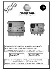
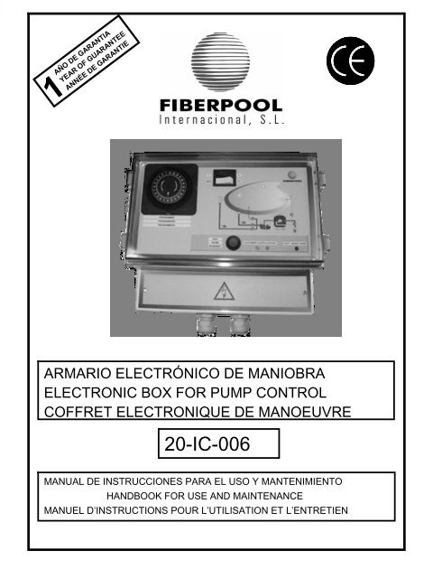
<strong>FIBERPOOL</strong> INTERNACIONALTECHNICAL SERVICE: Ponent, 2-4-6P.I. Sant Pere Molanta, 08799 OlèrdolaBARCELONAThe control panel should be installed by an authorizedtechnician. The main power line must be protected by adifferential and a magnetothermic. The control panel will befixed to the wall by a screw in the upper part (as if it were aneyebolt), and two more screws through the holes situated inthe inside of the connection box. The control box will be placedabove the electric pump.IP 54TEMPERATURE: from 5º to 70ºCVoltage acceptable: +- 10%Feed cables and cables connecting the electric pump are to beof a 1,5mm2 wires with an insulation material of 1000v.Connections to the terminals must be made with pre-insulatedconnectors.The electric pump must be earthed. All site work to wire up thecontrol panel should be done by an authorized technician,otherwise the manufacturer guarantee will not hold.WARNING: If the equipment is used for any purpose otherthan that specified by the manufacturer, the equipmentguarantees will not hold.Every 6 months, check for tightness all the connections. Theinstallation must comply with norms of II category. The supplycables to the equipment must be installed in a way so thatsafety is maintained and the insulation is no subject to anydamage.An anchoring device such as a packing gland must beused in order to prevent twisting and traction in the cable.FUNCTIONINGRegulated current limitation control for pumps from 0,3 "A" upto a maximum of:220vII……..3HP220vIII…….4HP380vIII…….5,5HPFlexibility of uses either for single phase or three phasepumps. System is disconnected when no current is detected.The circuit has the following functions:- Magnetic (short circuit). When working at high speed, facilityof disconnection to avoid excess consumption.- RESET switch activates all the functions on the board.- The system complies with EC norms.Ponent, 2-4-6 P.I. Sant Pere Molanta08799 Olèrdola, BARCELONAMOD: P.P.A.P. 220V II7380 v III 50/60HZ CorrienteCorriente equipo: 0.3 APotencia max.: 3hp (220V II) y 5.5hp(380V III)Nº de serie: FBP-00001MAIN DIAGRAMA - MAIN SWITCHI = start light on)0 = stop (light off)A’ – SWITCHMan = ManualAut = AutomaticB - ADJUSTMENTIn order to adjust the power consumption, we will follow thetwo frontal leds (green and yellow) using the potentiometerlocated at the left hand of the connection reglet. Turn thepotentiometer in a clockwise direction to reduce the amperage.C - BREAKDOWNThe red led indicates that there is a breakdown in the system.If this ever happens, please read the paragraph "Breakdowndetection".D - RE-SETWhen a breakdown has occurred push this switch to restart thesystem.Very important: Do not use it until you have read theparagraph titled "Breakdown detection".E - TIME CLOCKPOTENTIOMETER. Necessary element to adjust electricpump amperes (situated at the left hand of the connectionreglet)A’AEDBC4
<strong>FIBERPOOL</strong> INTERNACIONALN………………..Neutral terminalL1………………Supply phaseL2………………Supply phaseL3………………Supply phaseU………………..Feed to motorV………………..Feed to motorW……………….Feed to motorDepending whether the electric pump is single phase (II)or three phase (III) connections will be made according thefollowing diagram:W V U L3 L2 L1 NWVUL3L2L1NW V UL3L2L1Nalimentaciónalimentationfeedingmotor 220v. IIIpotenciometropotentiomètrepotentiometeralimentaciónalimentationfeedingred /réseausupply system220v. IIIalimentaciónalimentationfeedingmotor 380v. IIIpotenciometropotentiomètrepotentiometeralimentaciónalimentationfeedingred /réseausupply system380v. IIIalimentaciónalimentationfeedingmotor 220v. IIpotenciometropotentiomètrepotentiometeralimentaciónalimentationfeedingred /réseausupply system220v. IIPROCEDURE1. Turn the red switch to the "OFF" position. Connect the pumpto the control panel following the connection diagram(depending on the voltage used 220v II – 220v III – 380v III +N).Check that the supply voltage is correct using a voltmeter.2. Turn the red button on the front panel to "ON" position.Button will light up. After few seconds pump will function.Immediately after operate on the potentiometer, turn it untilgreen and yellow leds will blink.Very important: Check with an amperimeter that the pumpconsumption is the one specified by the manufacturer.Before completing the exact measurements andadjustments, please wait until the air has been removedfrom the closed circuit between pump and pool.3. The system has a time-clock for the pump operation in orderto ensure that the proper running amperes. If during this timethe pump adjustment has not been carried out, the protectioncircuit will be tripped. Reset again and adjust.BREAKDOWN DETECTIONIF THE SIGNAL LIGHTS FOR NEITHER THE SWITCH NORTHE BREAKDOWN LIGHT ARE ON: Check if the connectionsand supply voltage are correct.WHEN SWITCHING ON, THE PROTECTION CIRCUIT TRIPSAND THREE LEDS ARE MOMENTARILY LIGHT UP: Thisindicates a short circuit, magnetic protection, and immediatetrip. Call an authorized technician.THE GREEN LED IS NOT BLINKING: The pump is drawingthe pre-set level of power, tripping in 8 seconds. If this problemcontinues, please contact an authorized technician.BOTH GREEN AND YELLOW LEDS ARE NOT BLINKING:The pump is drawing double the pre-set level of power, trippingin 3 seconds. Please contact an authorized technician.NONE OF THE LEDS ARE FUNCTIONING: The pump is notdrawing sufficient power, tripping in 8 seconds. Press RESET.If this problem continues, please contact an authorized4. White switching located in the front panel will help you tochoose whether the pump operates in manual or automaticsystem.Manual: Switch in "MAN" positionAutomatic :Switch in "AUT" positionPROGRAMMING THE TIME CLOCK1. Adjust time by turning the programme disk in the arrowdirection.Hour time is indicated on the graduated dial.2. Set the connection programme at 15 minutes intervals bylocating the corresponding pins.3. The red segment visible shows the period of theprogrammed connection.3125
<strong>FIBERPOOL</strong> INTERNACIONALN…………………..Borne neutreL1………………….Entrée phaseL2………………….Entrée phaseL3………………….Entrée phaseU…………………..Sortie moteurV…………………..Sortie moteurW………………….Sortie moteurSelon si l'électro-pompe est monophasée (II) ou triphasée(III), la connexion devra être faite d'après le schémasuivant :W V U L3 L2 L1 NWVUL3L2L1NW V UL3L2L1Nalimentaciónalimentationfeedingmotor 220v. IIIpotenciometropotentiomètrepotentiometeralimentaciónalimentationfeedingred /réseausupply system220v. IIIalimentaciónalimentationfeedingmotor 380v. IIIpotenciometropotentiomètrepotentiometeralimentaciónalimentationfeedingred /réseausupply system380v. IIIalimentaciónalimentationfeedingmotor 220v. IIpotenciometropotentiomètrepotentiometeralimentaciónalimentationfeedingred /réseausupply system220v. IIFAÇON DE PROCEDER1. Placer l'interrupteur rouge en position "OFF", connecter lapompe au coffret selon le schéma de connexions (en tenantcompte du voltage 220vII – 220vIII – 380vIII + N).Avec l'aide d'un testeur, vérifier que le voltage d'entréesoit correct.2. Mettre l'interrupteur frontal (rouge) en position "ON".L'interrupteur s'allumera. Au bout de quelques secondes lapompe se mettra en fonctionnement, ensuite agir sur lepotentiomètre, le tourner jusqu'à ce que les lets vert et jauneclignotent.Très important : vérifier avec une pince ampéromètriqueque la consommation de la pompe soit celle indiquée parle fabricant. Prendre la mesure et régler quand lefonctionnement du circuit fermé entre la pompe et lapiscine soit sans air.3. Le système possède un temporizateur pour la mise enmarche de la pompe et pour qu'elle ait les ampèresnécessaires selon sa consommation. Si pendant ce temps-là,la pompe n'a pas été ajustée, il se produira un déclic deprotection, réenclenchez et ajuster.DETECTION DE PANNESNI L'INTERRUPTEUR, NI LA LUMIERE DE PANNE NES'ALLUMENT :Réviser la connexion et vérifier que le voltage soit correct.A LA MISE EN MARCHE, IL Y A UN DECLIC ET LES TROISLETS S'ALLUMENT MOMENTANEMENT : Avis decroisement, protection magnétique, déclic immédiat. Prévenirle service technique autorisé.LE LET VERT FIXE : La pompe consomme la marge que nouslui avons indiquée, déclic dans 8 secondes. Si le problèmepersiste prévenir le service technique autorisé.LES LETS VERT ET JAUNE SONT FIXES : La pompeconsomme le double, déclic en 3 secondes. Prévenir le servicetechnique autorisé.AUCUN LET NE SE MET EN MARCHE : La pompe neconsomme pas, déclic en 8 secondes. Appuyer sur "reset". Sicela persiste, prévenir le service technique autorisé.4. Avec le commutateur blanc de la partie frontale, nouspourrons choisir si la pompe doit travailler en manuel ou enautomatique Manuel : Commutateur en position "MAN"Automatique : Commutateur en position "AUT"PROGRAMMER LE TEMPORISATEUR1- Ajuster l'heure du jour en tournant le disque deprogrammation dans le sens de la flèche.L'heure du jour se lit dans le disque de l'échelle graduée.2 - Fixer le programme de connexions à intervalles de 15minutes, à l'aide des connecteurs correspondants3 - Le segment rouge visible indique la durée de la connexionprogrammée.3127
Declaración de conformidad:<strong>FIBERPOOL</strong> INTERNACIONAL, S.L., declara bajo su responsabilidad que susproductos 20-IC-<strong>006</strong> cumplen con la Directiva CE Máquinas, Consejo 89/392 ysiguientes modificaciones.Declaration of conformity:We, <strong>FIBERPOOL</strong> INTERNACIONAL, S.L., declare under our ownresponsability that our products 20-IC-<strong>006</strong> comply with the Council MachinesDirective 89/392 and following modifications.Déclaration de conformité:<strong>FIBERPOOL</strong> INTERNACIONAL, S.L., déclare sous sa responsabilité que lesproduits 20-IC-<strong>006</strong> sont conformes à la Directive Machine Conseil 89/392 etmodifications suivantes.Dichiarazione di conformità:Noi, <strong>FIBERPOOL</strong> INTERNACIONAL, S.L., dichiaramo sotto la Ns. solaresponsabilità che nostri prodotti 20-IC-<strong>006</strong> sono in comformità alla direttivamacchine 89/392 e successive modifiche.Konformitätserklärung:Die Firma <strong>FIBERPOOL</strong> INTERNACIONAL, S.L., erklärt unter ihrer vollenVerantwortlichkeit, daß die Produkte 20-IC-<strong>006</strong> den Maschinen-Richtlinien89/392,und späteren Änderungen, entsprechen.Apoderado: Antonio CatalánOlèrdola, 10-Octubre-2002Ponent 3-5-7 / P.I. Sant Pere Molanta08799 Olèrdola (BARCELONA)Tel:+34 938 180 016 / Fax:+34 938 180 718www.fiberpool.com