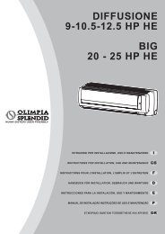
GAMMA STAR - Olimpia Splendid
GAMMA STAR - Olimpia Splendid
GAMMA STAR - Olimpia Splendid

Create successful ePaper yourself
Turn your PDF publications into a flip-book with our unique Google optimized e-Paper software.
48<br />
12<br />
I<br />
- Collegare il connettore dell’alimentazione<br />
del motorino delle alette<br />
direzionali (fig. 31 rif. A)<br />
- Rimontare la scocca sulla<br />
macchina (fig. 31).<br />
- Avvitare tutte le viti per il<br />
fissaggio della scocca e richiudere<br />
le due fessure con le relative<br />
strisce ad incastro (fig. 32).<br />
- Rimontare il frontalino di<br />
copertura led di segnalazione,<br />
prestando attenzione al verso, il<br />
foro per il pulsante di reset deve<br />
essere in corrispondenza del<br />
pulsante stesso (fig. 33).<br />
Una volta terminata l’installazione,<br />
si dovrà configurare l’elettronica in<br />
modo tale che tenga conto della<br />
stratificazione del calore in ambiente.<br />
Questa procedura è spiegata al<br />
paragrafo 2.5 (Prove funzionali e<br />
diagnosi di eventuali anomalie).<br />
31<br />
GB F D<br />
- Connect the connector of the<br />
engine power to the directional<br />
wings (fig. 31 ref. A)<br />
- Re-assemble the structure onto<br />
the machine (fig. 31).<br />
- Screw all of the fixing screws of<br />
the structure and close the two<br />
holes using the relative fixing strips<br />
(fig. 32).<br />
- Re-assemble the front cover of<br />
the signal led, making sure that it<br />
is assembled in the right position,<br />
the hole of the reset switch should<br />
be in line with the switch itself<br />
(fig. 33).<br />
After completing installation, the<br />
electronic parts of the air conditioner<br />
have to be configured so as to take<br />
into account the stratification of heat<br />
in the room. This procedure is outlined<br />
in paragraph 2.5 (Operating tests and<br />
diagnosis of possible malfunctions).<br />
A<br />
- Brancher le connecteur de<br />
l'alimentation du moteur des volets<br />
directionnels (fig. 31 réf. A)<br />
- Remonter la coque sur la machine<br />
(fig. 31).<br />
- Visser toutes les vis pour la<br />
fixation de la coque et refermer<br />
les deux fentes avec les bandes<br />
à clips relatives (fig. 32).<br />
- Remonter le panneau de<br />
protection des voyants de<br />
signalisation, en veillant au sens<br />
correct, le trou pour le bouton de<br />
reset doit correspondre à ce même<br />
bouton (fig. 33).<br />
Une fois l'installation terminée, il<br />
faudra configurer la partie<br />
électronique de sorte qu'elle prenne<br />
en compte la stratification de la<br />
chaleur de la pièce.<br />
Cette procédure est expliquée au<br />
paragraphe 2.5 (Essais de<br />
fonctionnement et disgnostics des<br />
éventuelles anomalies.<br />
32<br />
- Den Verbinder der Motorsteuerung<br />
der Lamellen (Abb. 31 Ref. A)<br />
anschließen.<br />
- Das Gehäuse wieder montieren<br />
(Abb. 31).<br />
- Alle Befestigungsschrauben des<br />
Gehäuses wieder festziehen und<br />
die beiden Schlitze mit den<br />
einsteckbaren Streifen wieder<br />
schließen (Abb. 32).<br />
- Die Abdeckplatte der<br />
Meldeleuchten wieder montieren<br />
und dabei auf die Montagerichtung<br />
achten: das Loch für die Reset-<br />
Taste muss mit derselben Taste<br />
übereinstimmen (Abb. 33).<br />
Nach der Installation ist die<br />
elektronische Einheit zu<br />
konfigurieren, wobei die im Raum<br />
vorhandene Temperaturschichtung<br />
(nur bei WP Geräten) zu<br />
berücksichtigen ist. Dieser Vorgang<br />
wird im Kapitel 2.5 beschrieben<br />
(Funktionsprüfungen und Diagnose<br />
eventueller Betriebsstörungen).