Create successful ePaper yourself
Turn your PDF publications into a flip-book with our unique Google optimized e-Paper software.
FORK INSTALLATION – SINGLE CROWN FORKS<br />
1. Remove the old fork from your bicycle.<br />
2. Measure and cut the steerer tube to fit your bicycle head tube (see CAUTION<br />
above). You can use your old fork as a guide for cutti ng the steerer tu be leng th .<br />
3. Remove the headset crown race from the old fork and press onto the fork<br />
steerer until the race is seated snugly against the top of the crown per the<br />
headset manufacturer’s instructions.<br />
4. Clean and grease the headset bearings and races per the headset<br />
manufacturer’s instructions.<br />
5. Install the lower bearings (if applicable) on fork crown race per the headset<br />
manufacturer’s instructions.<br />
6. Insert the steerer tube into the head tube of the frame.<br />
7. Install the upper bearings, stem spacers, and stem.<br />
8. Install the stem cap and bolt. Tighten the bolt to headset manufacturer’s<br />
specifications.<br />
9. Install the handlebars and torque the stem pinch screws or stem clamping<br />
system to stem manufacturer’s specifications.<br />
10. Install the brakes and adjust per the brake manufacturer’s instructions.<br />
11. For forks equipped with IT or ClickIt remote lockout levers, install the lever in<br />
an easily accessible position and torque to values indicated in Table 6 at the<br />
back of this manual.<br />
12. For forks with standard dropouts (non through axle), adjust the front wheel<br />
quick release to clear the 0.275” (7 mm) thick secondary catch dropout. The<br />
quick release must be tightened to quick release manufacturer’s specifications<br />
after it is properly seated into the dropout counter bores. Ensure that there is<br />
adequate thread engagement (4 or more threads with the release adjusted to<br />
lock). Refer to your bicycle owners manual on the proper use and adjustment<br />
of the quick release lever. NOTE: 2006 forks with standard dropouts are<br />
equipped with a secondary catch dropout to retain the wheel in the fork in the<br />
event the quick release comes loose.<br />
13. To install the hex axle, simply slip the axle into the dropout, small axle hex<br />
side first into the large dropout hex. Thread in the set bolt into the small hex<br />
side and snug slightly. Push the fork up and down a few times to center the<br />
axle and hub and then tighten all pinch bolts to recommendations found in<br />
Table 6.<br />
14. Install the brake cable per manufacturer instructions.<br />
FORK INSTALLATION – DUAL CROWN FORKS<br />
1. Remove the old fork from your bicycle.<br />
2. Measure and cut the steerer tube to fit your bicycle head tube. You can use<br />
your old fork as a guide for cutting the steerer tube length. To determine which<br />
upper triple clamp your frame will need see Table 5.<br />
3. Remove the headset crown race from the old fork and press onto the fork<br />
steerer until the race is seated snugly against the top of the crown per the<br />
headset manufacturer’s instructions.<br />
4. Clean and grease the headset bearings and races per the headset<br />
manufacturer’s instructions.<br />
5. Install the lower bearings (if applicable) on fork crown race per the headset<br />
manufacturer’s instructions.<br />
6. Insert the steerer tube into the head tube of the frame.<br />
7. Install the upper bearings, stem spacers, upper triple clamp and stem or<br />
integrated upper handlebar stem clamp.<br />
8. Install the stem cap and bolt. Tighten the bolt to headset manufacturer’s<br />
specifications.<br />
9. Install the handlebars and torque the stem pinch screws or stem clamping<br />
system to stem manufacturer’s specifications. Triple clamp, steerer tube, and<br />
handlebar bolts (integrated crown/stem models only) should be tightened to<br />
recommendations found in Table 6.<br />
10. Install the brakes and adjust per the brake manufacturer’s instructions.<br />
11. Adjust stanchion legs in the upper and lower crowns. The top of the lower<br />
clamp must not be more than 15mm from the step-down point in the upper<br />
stanchion tube leg.<br />
12. For forks with standard dropouts (non through axle), adjust the front wheel<br />
quick release to clear the 0.275” (7 mm) thick secondary catch dropout. The<br />
quick release must be tightened to manufacturer’s specifications after it is<br />
properly seated into the dropout counter bores. Ensure that there is adequate<br />
thread engagement (4 or more threads with the release adjusted to lock).<br />
Refer to your bicycle owners manual on the proper use and adjustment of the<br />
4<br />
quick release lever. NOTE: 2006 forks with standard dropouts are equipped<br />
with a secondary catch dropout to retain the wheel in the fork in the event the<br />
quick release comes loose.<br />
13. To install the hex axle, simply slip the axle into the dropout, small axle hex<br />
side first into the large dropout hex. Thread in the set bolt into the small hex<br />
side and snug slightly. Push the fork up and down a few times to center the<br />
axle and hub and then tighten all pinch bolts to recommendations found in<br />
Table 6.<br />
14. Install the brake cable per manufacturer’s instructions (see WARNING below.)<br />
BRAKE CABLE INSTALLATION<br />
FAILURE TO PROPERLY ROUTE AND SECURELY ATTACH<br />
THE FRONT BRAKE CABLE TO THE FORK CAN CAUSE<br />
SERIOUS INJURY OR DEATH.<br />
Included with the fork is a small black cable guide that can be attached to the fork<br />
to aid in routing cables to disc brake calipers. The best method we’ve found is to<br />
attach the cable so that it runs down the outside of the left fork leg. Make sure the<br />
brake line is not crimped and does not touch the tire as the fork moves through its<br />
range of travel.<br />
WHEN INSTALLING THE WHEEL WITH A PROPERLY<br />
INFLATED TIRE, CHECK TO MAKE SURE THE FORK<br />
ACHIEVES MINIMUM TIRE CLEARANCE. FAILURE TO CONFORM TO<br />
RECOMMENDED TIRE CLEARANCE SPECIFICATIONS MAY CAUSE THE TIRE TO<br />
STOP SUDDENLY DURING USE CAUSING PERSONAL INJURY OR DEATH.<br />
1. Measure from the highest point on the tire to the bottom of the brake arch<br />
(see Figure A). See Table 1 for minimum brake arch clearance. All figures and<br />
tables are located at the back of this manual.<br />
2. Measure the tire at maximum width (see Figure B). See Table 1 for maximum<br />
tire width.<br />
INITIAL SET-UP<br />
MEASURING TRAVEL<br />
To determine how much travel your fork has, simply measure the distance from the<br />
top of the seal wiper on the lowers (or the top of the fork boot for LOLA, EMPIRE,<br />
TRACE, and AXEL models equipped with fork boots) to the bottom of the crown.<br />
Please measure on the outside of the fork leg since some crowns are angle cut and<br />
overlap the stanchion more on the inside of the leg than the outside. See Table 2 to<br />
determine travel.<br />
MEASURING SAG<br />
You’ll need a tape measure, a pencil, a piece of paper and a helper.<br />
1. Measure the distance from the front axle’s centerline to the bottom of the<br />
crown when no one is sitting on the bike and write down this measurement.<br />
(Remember the exact locations of the two points because you’ll need to use<br />
them later.)<br />
2. Have the rider sit on the bike and measure the distance between the same two<br />
points as in step one. It is important to be in the normal riding position<br />
(weight centered) with your feet on the pedals.<br />
3. Subtract the second measurement from the first. The resulting measurement<br />
is the static sag (see Table 3).<br />
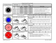
4. On coil forks with preload adjusters, turning the knob clockwise increases<br />
spring preload and decreases sag, while turning the knob counterclockwise<br />
decreases spring preload and increases sag.<br />
5. On air forks, remove the Schrader air cap located on the top or on the bottom<br />
of the left leg and, using a dedicated shock pump (<strong>Manitou</strong> part #85-4162),<br />
inflate the fork with the desired pressure. Be aware that sometimes air<br />
systems lose a small amount of pressure when the pump is removed, so you<br />
may want to check exactly how much your pump loses by reinstalling it after<br />
you have set and checked the pressure.<br />
When setting sag on forks featuring IT (Infinite Travel) technology, see<br />
“ADJUSTING MAIN SPRING AIR PRESSURE” below.<br />
6. If adjusting the preload or air pressure does not provide the proper sag, you<br />
may require a new ride kit. Please see recommended ride kits below.