Robbe Cardinal.pdf - RCtube.eu
Robbe Cardinal.pdf - RCtube.eu
Robbe Cardinal.pdf - RCtube.eu

You also want an ePaper? Increase the reach of your titles
YUMPU automatically turns print PDFs into web optimized ePapers that Google loves.
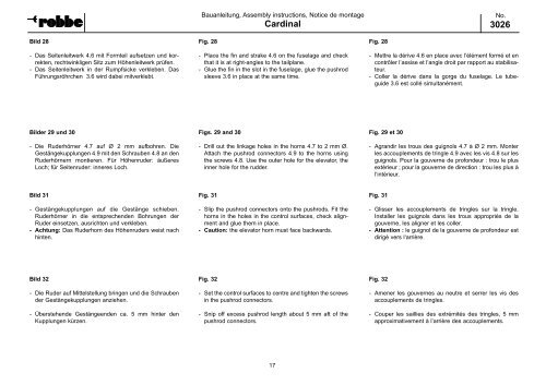
Bild 28<br />
- Das Seitenleitwerk 4.6 mit Formteil aufsetzen und korrekten,<br />
rechtwinkligen Sitz zum Höhenleitwerk prüfen.<br />
- Das Seitenleitwerk in der Rumpfsicke verkleben. Das<br />
Führungsröhrchen 3.6 wird dabei mitverklebt.<br />
Bilder 29 und 30<br />
- Die Ruderhörner 4.7 auf Ø 2 mm aufbohren. Die<br />
Gestängekupplungen 4.9 mit den Schrauben 4.8 an den<br />
Ruderhörnern montieren. Für Höhenruder: äußeres<br />
Loch; für Seitenruder: inneres Loch.<br />
Bild 31<br />
- Gestängekupplungen auf die Gestänge schieben.<br />
Ruderhörner in die entsprechenden Bohrungen der<br />
Ruder einsetzen, ausrichten und verkleben.<br />
- Achtung: Das Ruderhorn des Höhenruders weist nach<br />
hinten.<br />
Bild 32<br />
- Die Ruder auf Mittelstellung bringen und die Schrauben<br />
der Gestängekupplungen anziehen.<br />
- Überstehende Gestängeenden ca. 5 mm hinter den<br />
Kupplungen kürzen.<br />
Bauanleitung, Assembly instructions, Notice de montage<br />
<strong>Cardinal</strong><br />
Fig. 28<br />
- Place the fin and strake 4.6 on the fuselage and check<br />
that it is at right-angles to the tailplane.<br />
- Glue the fin in the slot in the fuselage, glue the pushrod<br />
sleeve 3.6 in place at the same time.<br />
Figs. 29 and 30<br />
- Drill out the linkage holes in the horns 4.7 to 2 mm Ø.<br />
Attach the pushrod connectors 4.9 to the horns using<br />
the screws 4.8. Use the outer hole for the elevator, the<br />
inner hole for the rudder.<br />
Fig. 31<br />
- Slip the pushrod connectors onto the pushrods. Fit the<br />
horns in the holes in the control surfaces, check alignment<br />
and glue them in place.<br />
- Caution: the elevator horn must face backwards.<br />
Fig. 32<br />
- Set the control surfaces to centre and tighten the screws<br />
in the pushrod connectors.<br />
- Snip off excess pushrod length about 5 mm aft of the<br />
pushrod connectors.<br />
17<br />
Fig. 28<br />
No.<br />
3026<br />
- Mettre la dérive 4.6 en place avec l’élément formé et en<br />
contrôler l’assise et l’angle droit par rapport au stabilisat<strong>eu</strong>r.<br />
- Coller la dérive dans la gorge du fuselage. Le tubeguide<br />
3.6 est collé simultanément.<br />
Fig. 29 et 30<br />
- Agrandir les trous des guignols 4.7 à Ø 2 mm. Monter<br />
les accouplements de tringle 4.9 avec les vis 4.8 sur les<br />
guignols. Pour la gouverne de profond<strong>eu</strong>r : trou le plus<br />
extéri<strong>eu</strong>r ; pour la gouverne de direction : trou les plus à<br />
l‘intéri<strong>eu</strong>r.<br />
Fig. 31<br />
- Glisser les accouplements de tringles sur la tringle.<br />
Installer les guignols dans les trous appropriés de la<br />
gouverne, les aligner et les coller.<br />
- Attention : le guignol de la gouverne de profond<strong>eu</strong>r est<br />
dirigé vers l‘arrière.<br />
Fig. 32<br />
- Amener les gouvernes au n<strong>eu</strong>tre et serrer les vis des<br />
accouplements de tringles.<br />
- Couper les saillies des extrémités des tringles, 5 mm<br />
approximativement à l’arrière des accouplements.