Robbe Cardinal.pdf - RCtube.eu
Robbe Cardinal.pdf - RCtube.eu
Robbe Cardinal.pdf - RCtube.eu

Create successful ePaper yourself
Turn your PDF publications into a flip-book with our unique Google optimized e-Paper software.
Bild 1<br />
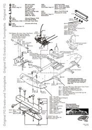
Hinweis zu den Angüssen: Alle Angüsse an den Arcel-<br />
Teilen mit einem scharfen Messer entfernen<br />
Baustufe 1, die Tragfläche<br />
Nr. Bezeichnung, Maße in mm Stück<br />
1.1 Tragflächenhälfte rechts 1<br />
1.2 Tragflächenhälfte links 1<br />
1.3 Hütchen (Lochverstärkung) 1<br />
Bild 2<br />
- Die Tragflächenhälften 1.1 und 1.2 mit Sekundenkleber<br />
und Aktivator deckungsgleich zusammenkleben.<br />
Bild 3<br />
- Das Hütchen 1.3 als Auflage für die<br />
Tragflächenschraube mit Sekundenkleber einkleben.<br />
Das Hütchen ist aus Darstellungsgründen schwarz eingefärbt.<br />
Bild 4<br />
- Die Bohrung in der Tragfläche durch das Hütchen mit<br />
einer Rundfeile auffeilen.<br />
Bauanleitung, Assembly instructions, Notice de montage<br />
<strong>Cardinal</strong><br />
Fig. 1<br />
Note - moulding flash: remove all excess material attached<br />
to the Arcel components using a sharp knife.<br />
Stage 1, the wing<br />
No. Description, size in mm No. off<br />
1.1 Right wing panel 1<br />
1.2 Left wing panel 1<br />
1.3 Top-hat bush (hole reinforcement) 1<br />
Fig. 2<br />
- Glue the wing panels 1.1 and 1.2 together using cyano<br />
and activator. Take care to keep all edges and faces<br />
flush.<br />
Fig. 3<br />
- Glue the top-hat bush 1.3 in the hole for the wing retainer<br />
screw, where it acts as a reinforcement. The bush is<br />
shown black for clarity.<br />
Fig. 4<br />
- Continue the hole right through the wing by twisting a<br />
round file through the top-hat bush.<br />
5<br />
Fig. 1<br />
No.<br />
3026<br />
Recommandation concernant les bavures d’injection :<br />
ébarber tous les éléments en Arcel à l’aide d’un couteau<br />
bien aiguisé<br />
Stade 1,l’aile<br />
N° Désignation, cotes en mm Nbre de pièces<br />
1.1 demi-aile droite 1<br />
1.2 demi-aile gauche 1<br />
1.3 calotte (renfort d’alésage) 1<br />
Fig. 2<br />
- Coller les demi-ailes 1.1 et 1.2 exactement ensemble<br />
avec de la colle cyanoacrylate et un activat<strong>eu</strong>r.<br />
Fig. 3<br />
- Coller la calotte 1.3 comme embout pour la vis de l’aile<br />
avec de la colle cyanoacrylate.<br />
Pour des raisons de lisibilité, la calotte est représentée<br />
en noir.<br />
Fig. 4<br />
- Limer l’orifice dans l’aile au travers de la calotte à l’aide<br />
d’une lime ronde.