ESPMod Manual 7 - Rain Bird
ESPMod Manual 7 - Rain Bird
ESPMod Manual 7 - Rain Bird

Create successful ePaper yourself
Turn your PDF publications into a flip-book with our unique Google optimized e-Paper software.
Français Español English<br />
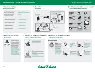
1. Assurez-vous que le transformateur<br />
N’EST PAS branché.<br />
2. Passez les trois câbles du<br />
transformateur par le trou inférieur<br />
gauche du boîtier. Tirez ensuite<br />
environ 30 cm de câble à l’intérieur<br />
du boîtier.<br />
3. Faites un nœud lâche au câble à<br />
l’intérieur du boîtier afin d’éviter de<br />
tirer directement sur le câble au<br />
niveau du bornier.<br />
4. Sur le bornier horizontal se situant en<br />
haut du boîtier, connectez le câble<br />
vert/jaune à la borne « GND ».<br />
5. Connectez l’un des deux câbles<br />
restants à une borne « 24V ».<br />
Connectez l’autre câble à la seconde<br />
borne « 24V ». Le choix de l’un où<br />
de l’autre câble et le choix de l’une<br />
ou l’autre borne 24V n’ont pas<br />
d’importance. La polarité de ces<br />
câbles n’a pas d’incidence.<br />
1. Asegúrese que el transformador NO<br />
esté enchufado.<br />
2. Pase los tres cables del<br />
transformador a través del orificio<br />
izquierdo de la parte inferior del<br />
gabinete. Luego ingrese unas 12”<br />
del cable dentro del gabinete.<br />
3. Haga un nudo flojo con el cable, en la<br />
parte interior del controlador, de<br />
modo de prevenir cualquier tensión<br />
sobre los terminales del conectador.<br />
4. Sobre la tira terminal horizontal<br />
ubicada en la parte superior del<br />
gabinete del controlador, conecte el<br />
cable verde al terminal “GND”.<br />
5. Conecte uno de los dos cables<br />
restantes al terminal “24 VCA”.<br />
Conecte el otro cable al segundo<br />
terminal “24 VCA”. Conecte<br />
cualquiera de los cables a cualquiera<br />
de los terminales 24 VCA; la<br />
polaridad de estos cables no es<br />
importante.<br />
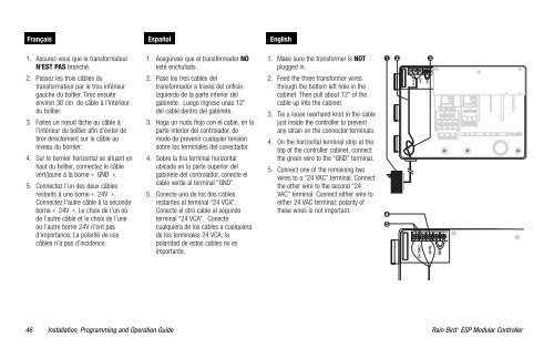
1. Make sure the transformer is NOT<br />
plugged in.<br />
2. Feed the three transformer wires<br />
through the bottom left hole in the<br />
cabinet. Then pull about 12” of the<br />
cable up into the cabinet.<br />
3. Tie a loose overhand knot in the cable<br />
just inside the controller to prevent<br />
any strain on the connector terminals.<br />
4. On the horizontal terminal strip at the<br />
top of the controller cabinet, connect<br />
the green wire to the “GND” terminal.<br />
5. Connect one of the remaining two<br />
wires to a “24 VAC” terminal. Connect<br />
the other wire to the second “24<br />
VAC” terminal. Connect either wire to<br />
either 24 VAC terminal; polarity of<br />
these wires is not important.<br />
46 <strong>Rain</strong> <strong>Bird</strong> ®<br />
Installation, Programming and Operation Guide<br />
ESP Modular Controller