Flexel® 3D LevMix System for Drum
Flexel® 3D LevMix System for Drum
Flexel® 3D LevMix System for Drum

Create successful ePaper yourself
Turn your PDF publications into a flip-book with our unique Google optimized e-Paper software.
Hardware Manual | Hardwareanleitung | Manuel de l'équipement |<br />
Manuale dell'hardware | Manual del soporte físico<br />
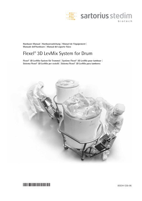
Flexel ® <strong>3D</strong> <strong>LevMix</strong> <strong>System</strong> <strong>for</strong> <strong>Drum</strong><br />
Flexel ® <strong>3D</strong> <strong>LevMix</strong>-<strong>System</strong> für Trommel | Système Flexel ® <strong>3D</strong> <strong>LevMix</strong> pour tambour |<br />
Sistema Flexel ® <strong>3D</strong> <strong>LevMix</strong> per cestelli | Sistema Flexel ® <strong>3D</strong> <strong>LevMix</strong> para tambores<br />
85034-536-06
2<br />
English page 3<br />
Deutsch Seite 16<br />
Français page 29<br />
Italiano pagina 42<br />
Español página 55
!<br />
Safeguards and Precautions Table of Contents<br />
1. Read and follow all instructions<br />
in this manual carefully, and retain<br />
this manual <strong>for</strong> future reference.<br />
2. Do not use this instrument in<br />
any manner inconsistent with these<br />
operating instructions or under<br />
any conditions that exceed the<br />
environmental specifications stated.<br />
3. Be sure the power supplied to<br />
this instrument matches the specifications<br />
indicated on the front panel<br />
of the control box and described in<br />
Specifications section.<br />
4. If the drive unit is transported<br />
or stored in colder temperatures<br />
than the operating environment it<br />
is necessary to wait 1–2 hours to<br />
equalize the internal temperatures<br />
of the drive unit be<strong>for</strong>e turning<br />
it on.<br />
5. Be sure all power is disconnected<br />
be<strong>for</strong>e opening, assembling or<br />
disassembling the superconductive<br />
drive unit or its control box.<br />
6. For full compliance with CE<br />
specifications, be sure the appropriate<br />
ground connection is made.<br />
7. For technical assistance contact<br />
the Sartorius Stedim Biotech sales<br />
organization.<br />
8. Each Flexel ® <strong>3D</strong> <strong>LevMix</strong> <strong>System</strong><br />
<strong>for</strong> <strong>Drum</strong> contains a magnetic<br />
impeller, which is the source of<br />
a strong magnetic field in close<br />
vicinity (12 inches) of the impeller.<br />
People using any electronic medical<br />
devices, such as pacemakers, should<br />
not be involved in the close handling<br />
of Flexel ® <strong>3D</strong> <strong>LevMix</strong> Bags <strong>for</strong><br />
drums, magnetic chargers, impellers<br />
or test impellers.<br />
9. Keep supplied magnetic shields<br />
on bags, magnetic chargers and<br />
impellers when not in use.<br />
Do not open machine or control<br />
box while the Drive Unit is plugged<br />
in.<br />
Do not submerge drive in water.<br />
Do not cut ground plug.<br />
Important In<strong>for</strong>mation<br />
Portable Appliance Test (PAT) -<br />
U.K. Procedure<br />
Insulation Resistance Test<br />
Background<br />
For U.K. users of the Flexel ® <strong>3D</strong> <strong>LevMix</strong><br />
<strong>System</strong> who wish to per<strong>for</strong>m the PAT Test,<br />
please consider the following:<br />
Flexel ® <strong>3D</strong> <strong>LevMix</strong> <strong>System</strong> Electronics<br />
The electronics of the DB-200 superconductive<br />
mixer drive units contain a<br />
surge suppression board to protect the main<br />
controller from damaging electrical surges<br />
on the AC main line per CE requirements.<br />
The electrical components of the surge<br />
suppression board are Metal Oxide Varisters<br />
(MOV). MOVs provide surge suppression to<br />
the electronics by shorting high voltage<br />
transients to ground.<br />
PAT Test<br />
During the Insulation Resistance Test in<br />
PAT, the testers short together live and<br />
neutral conductors and apply 500VDC<br />
between these conductors and earth. As a<br />
result of the surge protection board, “low”<br />
readings will result as the MOVs short high<br />
voltage to ground. This is normal characteristic<br />
of the electronics. To properly conduct<br />
the PAT test, it is necessary and proper to<br />
bypass the surge suppression circuit.<br />
Consult your Sartorius Stedim Biotech<br />
Service Representative <strong>for</strong> Northern Europe<br />
<strong>for</strong> the proper Insulation Resistance Test<br />
procedure that can determine if a fault<br />
exists.<br />
Safeguards and Precautions 2<br />
Table of Contents 2<br />
1. Specifications 3<br />
2. Overview 3<br />
3. Principal of Operation 3<br />
4. Flexel ® <strong>3D</strong> <strong>LevMix</strong> <strong>System</strong><br />
<strong>for</strong> <strong>Drum</strong> Components and<br />
Accessories 4<br />
5. Superconducting Drive Unit 7<br />
6. Charging the Superconductors 8<br />
7. Dolly – Tank Assembly 9<br />
8. Flexel ® <strong>3D</strong> <strong>LevMix</strong> Bag <strong>for</strong><br />
drums – Interface Assembly 10<br />
9. Inserting Flexel ® <strong>3D</strong> <strong>LevMix</strong><br />
Bag <strong>for</strong> drums Into Tank 11<br />
10. Coupling the Flexel ® <strong>3D</strong> <strong>LevMix</strong><br />
Bag <strong>for</strong> drums with the<br />
Superconducting Drive Unit 12<br />
11. Mixing 13<br />
12. Removing the Superconducting<br />
Drive Unit From the Tank 13<br />
Maintenance and Care of the<br />
Superconducting Drive Unit 13<br />
13. Service 14<br />
3
1. Specifications 2. Overview 3. Principle of Operation<br />
Power requirements:<br />
single phase, 230 V AC, 3 A.<br />
Wattage:<br />
less than 350 Watts at a<br />
maximum impeller speed.<br />
Impeller speed:<br />
0–180 RPM.<br />
Ambient temperature:<br />
4–30°C.<br />
Max humidity:<br />
75%, Non-Condensing.<br />
4<br />
The Flexel ® <strong>3D</strong> <strong>LevMix</strong> <strong>System</strong> <strong>for</strong> <strong>Drum</strong> is a<br />
unique single-use mixing solution utilizing<br />
cylindrical tank geometries combined<br />
with the market leading LevTech ® levitated<br />
impeller and Sartorius Stedim Biotech<br />
Flexel ® <strong>3D</strong> Bag technologies.<br />
The system hardware has three major<br />
components:<br />
1. MDPE cylindrical mixing drums are<br />
designed to fit perfectly with the Flexel ® <strong>3D</strong><br />
<strong>LevMix</strong> Bags <strong>for</strong> drums and the integrated<br />
impeller. The tanks are positioned on a<br />
stainless steel dolly <strong>for</strong> drum to ensure a<br />
safe operation as well as easy access and<br />
drainage. The dolly <strong>for</strong> drum contains a<br />
railed port <strong>for</strong> coupling the mobile superconducting<br />
drive unit with the Flexel ® <strong>3D</strong><br />
<strong>LevMix</strong> bag. They are available in 50 L,<br />
100 L, 200 L, 300 L, 370 L and 560 L<br />
volumes to be used with the 50 L to 560 L<br />
Flexel ® <strong>3D</strong> <strong>LevMix</strong> Bags <strong>for</strong> drums.<br />
2. Stainless steel mixing tanks are available<br />
in 50 L, 100 L, 200 L, 300 L and 370 L.<br />
The tanks are positioned on a stainless steel<br />
dolly <strong>for</strong> drum to ensure a safe operation as<br />
well as easy access and drainage. In the volumes<br />
of 560 L, 750 L and 1,000 L the tanks<br />
are mounted on legs that are equipped with<br />
cleanroom wheels <strong>for</strong> increased mobility.<br />
They incorporate an interface railed port <strong>for</strong><br />
coupling the superconducting drive unit<br />
with the impeller inside the bag.<br />
3. LevTech ® superconducting drive unit<br />
levitates and rotates the single use magnetic<br />
impeller without seals, bearings or surface<br />
contact. This allows the Flexel ® <strong>3D</strong> <strong>LevMix</strong><br />
system to efficiently mix powders, suspensions,<br />
solutions or emulsions. The drive<br />
unit is mobile, cart-mounted and designed<br />
to interface with mixing tanks of different<br />
volumes.<br />
Flexel ® <strong>3D</strong> <strong>LevMix</strong> <strong>System</strong> <strong>for</strong> <strong>Drum</strong> is based<br />
on non-contact magnetic coupling between<br />
conventional permanent magnets in the<br />
impeller and superconducting material in<br />
the drive. Superconducting material has the<br />
ability to trap the magnetic field generated<br />
by the permanent magnets and “lock the<br />
magnetic field in memory” in an equilibrium<br />
position.<br />
Figure 1. Non contact magnetic coupling<br />
between the permanent magnet and superconductors.<br />
The superconducting material<br />
traps the magnetic field from the magnet,<br />
resulting in stable mechanical coupling<br />
without physical contact.<br />
The trapped magnetic field behaves like<br />
mechanical springs; if the magnet is moved<br />
up, down or sideways by outside <strong>for</strong>ces (e.g.,<br />
gravity or angular torque), it will tend to be<br />
pulled back to an equilibrium position. The<br />
peculiar nature of magnet-superconductor<br />
interaction ties the two bodies together<br />
resulting in a very stable mechanical couple<br />
with finite equilibrium separation. This<br />
peculiar stability cannot be attained in conventional<br />
mixer designs that employ two<br />
permanent magnets. In these mixers, the<br />
two magnets strongly attract one another<br />
and exert that <strong>for</strong>ce on the bearing in the<br />
impeller. Thus, the magnet-superconductor<br />
couple is the basis <strong>for</strong> a revolutionary design<br />
of the non-contact magnetic levitation<br />
mixer.<br />
The Cryogenic temperatures (approx.<br />
–200°C) required <strong>for</strong> the superconducting<br />
material are achieved by an internal<br />
cryocooler (Sterling cycle refrigerator),<br />
which operates on 230 V 50|60 Hz AC<br />
power.
4. Flexel ® <strong>3D</strong> <strong>LevMix</strong> <strong>System</strong> <strong>for</strong> <strong>Drum</strong> Components and Accessories<br />
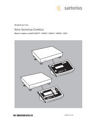
Figure 2. Flexel ® <strong>3D</strong> <strong>LevMix</strong> <strong>System</strong> <strong>for</strong> <strong>Drum</strong> consists of three primary components:<br />
1. Superconducting Drive Unit on Cart<br />
2. Elevated Retaining Tank<br />
3. Railed Port that Couples Drive Unit<br />
with the Flexel ® <strong>3D</strong> <strong>LevMix</strong> Bags <strong>for</strong><br />
drums<br />
A. drive unit handle<br />
B. control box<br />
C. locking latch<br />
D. levitation head<br />
E. guide bearings<br />
F. front wheels<br />
G. rear wheels<br />
H. centering aligner and magnetic clamp<br />
5
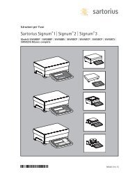
Pictures & Descriptions of Available Accessories<br />
I. Magnetic charger with shield (two types: LT-DBCI001, LT-DBCI005)<br />
II. Interface<br />
III. Centering aligner<br />
IV. Magnetic clamp<br />
V. Test impeller with shield (two types: LT-DBAK004, LT-DBAK007)<br />
VI. O-ring<br />
Figure A: From left to right, Magnetic Charger (LT-DBCI001), Shield <strong>for</strong> Magnetic Charger,<br />
(LT-DBAK011) and Magnetic Charger (LT-DBCI001) coupled with Shield. During the<br />
charging procedure, the ball bearing (red in far left picture) should rest on the surface of<br />
the levitation head of the drive unit.<br />
Figure B: From left to right, Magnetic Charger (LT-DBCI005), Shield <strong>for</strong> Magnetic Charger,<br />
(LT-DBAK011) and Magnetic Charger (LT-DBCI005) coupled with Shield. During the<br />
charging procedure, the ball bearing (red in far left picture) should rest on the surface of<br />
the levitation head of the drive unit.<br />
Magnetic Charger & Test Impeller Chart<br />
Magnetic Charger Corresponding Test Impeller Magnet Configuration<br />
LT-DBCI001 LT-DBAK004 6-magnet charger & impeller<br />
LT-DBCI005 LT-DBAK007 4-magnet charger & impeller<br />
Note:<br />
the appropriate magnetic charger must be used to set the drive machine <strong>for</strong> use with the<br />
corresponding impeller. The machine will not properly drive an impeller which does not have<br />
the corresponding magnet configuration.<br />
6
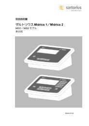
Figure C: Left: Drive- Flexel ® <strong>3D</strong> <strong>LevMix</strong> Bags <strong>for</strong> drums interface.<br />
Right: Interface is installed in the railed port of the dolly (locked by the O-ring).<br />
Figure D: Magnetic clamp (left) and Figure E: Magnetic clamp is assembled with<br />
centering aligner (right). the centering aligner prior to attachment to<br />
the Flexel ® <strong>3D</strong> <strong>LevMix</strong> Bags <strong>for</strong> drums.<br />
Figure F: Test impeller levitates above the<br />
head of the super-conductive drive unit<br />
during a levitation test.<br />
Magnetic Charger & Test Impeller Chart<br />
Magnetic Charger Corresponding Test Impeller Magnet Configuration<br />
LT-DBCI001 LT-DBAK004 6-magnet charger & impeller<br />
LT-DBCI005 LT-DBAK007 4-magnet charger & impeller<br />
Note:<br />
the appropriate magnetic charger must be used to set the drive machine <strong>for</strong> use with the<br />
corresponding impeller. The machine will not properly drive an impeller which does not have<br />
the corresponding magnet configuration.<br />
7
5. Superconducting Drive Unit<br />
The Superconducting drive unit is sealed <strong>for</strong> water|spray resistance and has a splash<br />
resistant control box. The unit is easily maneuvered <strong>for</strong> placement under the mixing tank.<br />
Figure 3. Location of components of drive unit control box<br />
8
6. Charging the Superconductors<br />
Figure 4. Sequence of steps <strong>for</strong> charging<br />
superconductors<br />
Procedure<br />
Be<strong>for</strong>e plugging in the machine, follow the<br />
steps below.<br />
A. If the drive unit is transported or stored<br />
in colder temperatures than the operating<br />
environment it is necessary to wait 2 hours<br />
to equalize the internal temperatures of the<br />
drive unit be<strong>for</strong>e turning it on.<br />
B. Ensure that the adjustable speed drive<br />
toggle switch is in the OFF (down) position<br />
and the RPM control knob is turned to<br />
zero (0), and remains in this position until<br />
charging is complete.<br />
C. Remove protective shield from magnetic<br />
charger and place magnetic charger with<br />
bearing in the receiving cavity on the<br />
levitation head.<br />
D. Identify the main power button on the<br />
control box:<br />
Connect the superconducting drive unit to<br />
a standard 230 V 50|60 Hz. power source,<br />
lift the clear plastic shield over the red main<br />
power button, and push the button IN so<br />
that it is illuminated. The RPM readout<br />
panel will not illuminate until charging is<br />
complete (35 minutes), at which time it<br />
should read 0 RPM. Ensure that electrical<br />
power remains connected to the machine<br />
even after charging is complete. To prevent<br />
accidental shut-off of the drive unit, keep<br />
the clear plastic shroud down to cover the<br />
main power button.<br />
Do not use alternative spacing|separating<br />
devices when charging the drive. Use only<br />
the magnetic charger provided in the kit.<br />
While drive unit is charging, you can continue<br />
with Dolly – Tank Assembly (Section 7).<br />
A. After the drive unit has charged <strong>for</strong><br />
35 minutes, lift the magnetic charger<br />
and replace the protective shield on the<br />
magnetic charger.<br />
B. Remove the protective shield from the<br />
test impeller and place the test impeller on<br />
the levitation head. At this point it should<br />
levitate freely above the surface of the<br />
levitation head. This will indicate that the<br />
machine is ready <strong>for</strong> operation.*<br />
C. Test <strong>for</strong> true rotation of levitated test<br />
impeller by moving the switch on the<br />
control box to the ON position and turn<br />
the RPM Regulator Knob clock-wise and<br />
set the arrow at 50. The levitated impeller<br />
will spin. The levitation gap must remain<br />
uni<strong>for</strong>m (no wobbling of the impeller)*.<br />
D. Move the switch on the control box to<br />
the OFF position and then remove the test<br />
impeller. (Do not try to remove the test<br />
impeller while it is spinning.) Replace the<br />
protective shield on the test impeller. The<br />
unit is now ready to be placed under the<br />
mixing tank to begin mixing.<br />
!<br />
Always put the protective shield<br />
back on the magnetic charger when<br />
charging procedure is complete.<br />
* If the test impeller does not levitate or<br />
substantial wobbling takes place (more<br />
than 1mm change in gap) the system<br />
must be reset. Turn the system off <strong>for</strong><br />
25 minutes and repeat set up procedure.<br />
If problem continues, contact a your<br />
Sartorius Stedim Biotech representative.<br />
9
7. Dolly – Tank Assembly<br />
A. The Dolly has a pre-cut hole over the<br />
drive port. Insert the Interface into this hole<br />
from below and apply the O-ring as shown<br />
to secure. It is not necessary to remove<br />
or replace the Interface after mixing or<br />
between batches.<br />
B. Position the plastic tank on the dolly. The<br />
bottom surface of the tank has two pre-cut<br />
holes: a small hole <strong>for</strong> the Flexel ® <strong>3D</strong> <strong>LevMix</strong><br />
Bags <strong>for</strong> drums drain and a larger hole <strong>for</strong><br />
the drive head. Line up the larger hole with<br />
the hole in the dolly over the drive port.<br />
The larger whole should fit loosely around<br />
the Interface.<br />
C. The schematic beside indicates the<br />
different tank positions when installed<br />
on dolly LT-DBMC034.<br />
10<br />
Dolly DBMC034 top view
8. Flexel ® <strong>3D</strong> <strong>LevMix</strong> Bags <strong>for</strong> <strong>Drum</strong> – Interface Assembly<br />
Figure 5. Assembly of dry Flexel ® <strong>3D</strong> <strong>LevMix</strong> Bags <strong>for</strong> <strong>Drum</strong> with interface<br />
Procedure<br />
A. Carefully open the EXTERNAL packaging<br />
of the Flexel ® <strong>3D</strong> <strong>LevMix</strong> Bags <strong>for</strong> <strong>Drum</strong>.<br />
A protective shield is magnetically attached<br />
to the outside of the bag over the locator.<br />
This shield must be removed from the bag<br />
be<strong>for</strong>e assembling the interface.<br />
B. Assemble the centering aligner and<br />
magnetic clamp as shown in Figure 5.<br />
11
9. Inserting Flexel ® <strong>3D</strong> <strong>LevMix</strong> Bags <strong>for</strong> <strong>Drum</strong> into Tank<br />
Figure 6. Flexel ® <strong>3D</strong> <strong>LevMix</strong> Bags <strong>for</strong> <strong>Drum</strong> – Tank Assembly<br />
12<br />
Procedure<br />
A. Place the Flexel ® <strong>3D</strong> <strong>LevMix</strong> Bags <strong>for</strong><br />
<strong>Drum</strong> in the plastic tank by aligning magnetic<br />
clamp with the large pre-cut port on<br />
the bottom surface of the tank and pull the<br />
bottom drain tube through the smaller port.<br />
B. Insert the magnetic clamp in the<br />
appropriate pre-cut port.<br />
C. Be<strong>for</strong>e filling the Flexel ® <strong>3D</strong> <strong>LevMix</strong> Bags<br />
<strong>for</strong> <strong>Drum</strong>, ensure that all tubes are clamped,<br />
with the exception of the filling tube.<br />
Ensure that the bottom drain tube is<br />
clamped.<br />
D. As Flexel ® <strong>3D</strong> <strong>LevMix</strong> Bags <strong>for</strong> <strong>Drum</strong><br />
starts to fill, gently pull the bottom<br />
surface of the bag to remove any wrinkles,<br />
especially near the impeller.<br />
Do not exceed recommended Flexel ® <strong>3D</strong><br />
<strong>LevMix</strong> Bags <strong>for</strong> <strong>Drum</strong> capacity.<br />
Do not alter the tube and|or impeller<br />
configuration of Flexel ® <strong>3D</strong> <strong>LevMix</strong> Bags<br />
<strong>for</strong> <strong>Drum</strong>.
10. Coupling the Flexel ® <strong>3D</strong> <strong>LevMix</strong> Bags <strong>for</strong> <strong>Drum</strong> with Superconducting Drive Unit<br />
Figure 7. Matching the drive to the railed port. Single latch unit (on the left) would work<br />
with 8” port only. In the double latch unit (on the right) use the latch that is closer to<br />
control box <strong>for</strong> 15” port and the latch that is further from the control box <strong>for</strong> 8” port.<br />
Figure 8. Coupling of superconducting drive unit with the Flexel ® <strong>3D</strong> <strong>LevMix</strong> Bags <strong>for</strong> drums<br />
can be accomplished only when the bag is filled with fluid (No coupling must be attempted<br />
with an empty or dry bag! The impeller will damage the bag.)<br />
Procedures<br />
A. Remove Magnetic Clamp from the Flexel ®<br />
<strong>3D</strong> <strong>LevMix</strong> Bags <strong>for</strong> <strong>Drum</strong>-tank assembly<br />
be<strong>for</strong>e coupling. To remove the magnetic<br />
clamp, reach underneath the drive port and<br />
carefully pull the magnetic clamp until it is<br />
free from the bag-tank assembly. Return the<br />
magnetic clamp to the supplied Accessories<br />
Box <strong>for</strong> future use.<br />
B. Make sure that the superconductive<br />
levitation drive and railed port match. If the<br />
drive has single locking latch it works only<br />
with 8” port. If the drive has two locking<br />
latches it can work with 8” port and 15”<br />
port. Determine what unit you have then<br />
determine what port size you have by<br />
measuring the port size as shown on Fig. 7.<br />
For the double latch unit use the latch that<br />
is closer to the control box <strong>for</strong> 15 “port and<br />
the other latch <strong>for</strong> 8”port, see Fig. 7<br />
C. Shift the latch toward the control box<br />
slightly, (as shown in the first segment of<br />
Figure 8).<br />
D. Carefully press down on the drive handle<br />
and raise the front wheels off the ground<br />
(as shown on the second segment of the<br />
Figure 8)<br />
E. Align the guide bearings with the guide<br />
rails on the drive port.<br />
F. Roll the superconductive drive unit along<br />
the rails all the way until the bearings are<br />
caught in the well located at the dead end<br />
of the rails.<br />
G. Using the drive unit handle, raise the<br />
superconductive drive unit to an upright<br />
position. While holding the drive unit in this<br />
position shift the latch toward the dolly|<br />
tank so that the cross bar rests on the<br />
grooves in the guide rails (as shown in the<br />
<strong>for</strong>th segment of Figure 8).<br />
Do not attempt to move the Dolly with the<br />
Drive Unit Handle when assembled. It may<br />
damage the superconducting drive unit.<br />
Always use the dolly push handle to move<br />
the Dolly or Dolly|Drive Unit assembly.<br />
Do not put fingers under Locking Lever<br />
when locking the Drive Unit onto the Dolly.<br />
13
11. Mixing 12. Removing Superconducting<br />
Drive Unit from Tank<br />
A. Turn the speed drive switch to the ON<br />
position.<br />
B. Adjust the RPM with the RPM Regulator<br />
Knob to desired speed.<br />
C. Mix according to application<br />
specifications.<br />
Do not attempt to mix in empty or dry<br />
Flexel ® <strong>3D</strong> <strong>LevMix</strong> Bags <strong>for</strong> drums. It may<br />
result in to damage of the film of the<br />
Flexel ® <strong>3D</strong> <strong>LevMix</strong> Bags <strong>for</strong> drums.<br />
14<br />
A. When mixing is complete, turn the RPM<br />
Regulator to zero (0) and turn the drive<br />
switch to the OFF position. (Ensure that<br />
electrical power remains connected to the<br />
machine when mixing multiple Flexel ® <strong>3D</strong><br />
<strong>LevMix</strong> Bags <strong>for</strong> drums consecutively.)<br />
B. Firmly hold the drive unit handle and<br />
raise the drive unit slightly to release the<br />
locking lever. Release the locking lever by<br />
pulling it toward the control box.<br />
C. Carefully lower the rear wheels of the<br />
drive unit to the floor and roll the drive unit<br />
on its rear wheels away from the dolly.<br />
D. Press down on the drive unit handle just<br />
until the guide bearings are free from the<br />
guide rails.<br />
E. Pull the drive unit slightly farther away<br />
from the dolly and carefully lower the front<br />
wheel to the ground.<br />
F. The tank can now be wheeled to another<br />
station on the elevated dolly. The Superconducting<br />
Drive Unit remains ready <strong>for</strong> mixing.<br />
G. To drain fluid from the Flexel ® <strong>3D</strong> <strong>LevMix</strong><br />
Bags <strong>for</strong> drums, unclamp the bottom drain<br />
tube.<br />
H. When the Flexel ® <strong>3D</strong> <strong>LevMix</strong> Bags <strong>for</strong><br />
drums is completely drained, remove the<br />
bag by carefully pulling the impeller seat<br />
and the drain tube out of their respective<br />
ports.<br />
I. Remove the centering aligner from the<br />
tank and return to the supplied Accessories<br />
Box <strong>for</strong> future use. The Interface should<br />
remain in its locked position <strong>for</strong> future use.<br />
Always put the protective shield back on<br />
the Flexel ® <strong>3D</strong> <strong>LevMix</strong> Bag <strong>for</strong> drums be<strong>for</strong>e<br />
disposal.<br />
J. Dispose of bag.<br />
Maintenance and Care of Superconducting<br />
Drive Unit<br />
The LevTech DB-200E Superconducting<br />
Drive is designed to operate 24/7 maintenance<br />
free. However, to minimize the wear,<br />
it is recommend that the drive be unplugged<br />
if it is not in use <strong>for</strong> more than 24 hours.<br />
Each time the drive is to be used, it is<br />
necessary to charge the superconductors.<br />
The drive should not operate continuously<br />
<strong>for</strong> more than 10 days without recharging<br />
the superconductors. To recharge superconductors<br />
the machine must be unplugged <strong>for</strong><br />
at least 25 minutes. Then follow charging<br />
procedures in section 5.
13. Sartorius Stedim Biotech Service<br />
The DB-200E was developed exclusively <strong>for</strong><br />
mixing fluids and solids in fluids in specially<br />
designed Flexel ® <strong>3D</strong> <strong>LevMix</strong> Bags <strong>for</strong> drums.<br />
Only use the machine <strong>for</strong> this purpose to<br />
ensure a long service life.<br />
Should your DB-200E require service,<br />
contact your local Sartorius Stedim Biotech<br />
Sales representative.<br />
The system or its components are <strong>for</strong> use<br />
under or may be covered by one or more<br />
of the following U.S. patent numbers:<br />
6,965,288<br />
6,758,593<br />
6,899,454<br />
6,494,613<br />
6,837,613<br />
6,416,215<br />
7,086,778<br />
* Other U.S. and <strong>for</strong>eign patents pending<br />
15
!<br />
16<br />
Sicherheitshinweise und Vorsichtsmaßnahmen Inhalt<br />
1. Lesen und beachten Sie alle<br />
Anweisungen in diesem Handbuch<br />
und bewahren Sie dieses Handbuch<br />
zum späteren Nachschlagen auf.<br />
2. Verwenden Sie dieses Gerät nicht<br />
für andere Zwecke als in dieser Betriebsanleitung<br />
beschrieben oder<br />
unter Bedingungen außerhalb der<br />
angegebenen Umgebungsbedingungen.<br />
3. Die Betriebsspannung für dieses<br />
Gerät muss den Angaben auf der<br />
Vorderseite des Steuerkastens und<br />
den Angaben im Abschnitt Technische<br />
Daten entsprechen.<br />
4. Wenn die Antriebseinheit bei kälteren<br />
Temperaturen als der Betriebstemperatur<br />
transportiert oder gelagert<br />
wird, ist vor dem Einschalten<br />
eine Wartezeit von ein bis zwei<br />
Stunden notwendig, damit sich die<br />
inneren Temperaturen der Antriebseinheit<br />
anpassen.<br />
5. Vor dem Öffnen, Zusammenbau<br />
oder Auseinanderbau der leitenden<br />
Antriebseinheit oder des Steuerkastens<br />
müssen alle Netzkabel getrennt<br />
sein.<br />
6. Um die CE-Vorschriften einzuhalten,<br />
muss die Verbindung entsprechend<br />
geerdet werden.<br />
7. Technische Unterstützung erhalten<br />
Sie von der Vertriebsorganisation<br />
von Sartorius Stedim Biotech.<br />
8. Jedes Flexel ® <strong>3D</strong> <strong>LevMix</strong>-<strong>System</strong><br />
für Trommeln enthält einen Magnetrührer,<br />
der in der unmittelbaren<br />
Nähe (30 cm) des Rührers ein starkes<br />
magnetisches Feld erzeugt.<br />
Personen mit elektronischen medizinischen<br />
Geräten, z. B. Herzschrittmachern,<br />
sollten nicht direkt in der<br />
Nähe der Flexel ® <strong>3D</strong> <strong>LevMix</strong>-Beutel<br />
für Trommeln, magnetische Ladevorrichtungen,<br />
Rührer oder Testrührer<br />
arbeiten.<br />
9. Bei Nichtverwendung der Beutel,<br />
Magnetrührer und Ladevorrichtung<br />
die mitgelieferten magnetischen<br />
Abschirmungen anbringen.<br />
Die Maschine oder den Steuerkasten<br />
bei eingesteckter Antriebseinheit<br />
nicht öffnen.<br />
Antrieb nicht in Wasser tauchen.<br />
Den Schutzleiter nicht unterbrechen.<br />
Wichtige In<strong>for</strong>mationen<br />
Test für tragbare Geräte (PAT) -<br />
Verfahren für Großbritannien<br />
Isolierwiderstandstest<br />
Hintergrund<br />
Benutzer des Flexel ® <strong>3D</strong> <strong>LevMix</strong>-<strong>System</strong>s in<br />
Großbritannien, die den PAT-Test durchführen<br />
möchten, müssen Folgendes beachten:<br />
Flexel ® <strong>3D</strong> <strong>LevMix</strong>-<strong>System</strong>elektronik<br />
Die Elektronik der superleitenden Mischer–<br />
antriebseinheiten DB-200 besitzt einen<br />
Überspannungsschutz zum Schutz des<br />
Hauptcontrollers vor Schäden durch Überspannungen<br />
in der Netzleitung entsprechend<br />
den CE-Vorschriften. Die elektrischen Bauteile<br />
dieses Überspannungsschuztes sind<br />
Metall-Oxid-Varistoren (MOV). Diese MOVs<br />
unterdrücken Überspannungen zur Elektronik<br />
durch Kurzschluss von Spannungsspitzen<br />
mit Masse.<br />
PAT-Test<br />
Beim Isolierwiderstandstest in PAT verbinden<br />
die Prüfgeräte spannungsführende und Neutralleiter<br />
und legen eine Gleichspannung von<br />
500 V zwischen diesen Leitern und der<br />
Masse an. Aufgrund des Überspannungsschutzes<br />
werden niedrige Messergebnisse<br />
angezeigt, da die MOVs die hohe Spannung<br />
gegen Masse ableiten. Dies ist die normale<br />
Eigenschaft der Elektronikbauteile. Zur korrekten<br />
Durchführung des PAT-Tests muss<br />
diese Überspannungsschutzschaltung korrekt<br />
umgangen werden.<br />
Wenden Sie sich an Ihren Kundendienstvertreter<br />
von Sartorius Stedim Biotech für<br />
Nordeuropa, um den Isolierwiderstandstest<br />
so durchzuführen, dass Fehler erkannt werden<br />
können.<br />
Sicherheitshinweise<br />
und Vorsichtsmaßnahmen 16<br />
Inhalt 16<br />
1. Technische Daten 17<br />
2. Überblick 17<br />
3. Funktionsprinzip 17<br />
4. Flexel ® <strong>3D</strong> <strong>LevMix</strong>-<strong>System</strong><br />
für Trommelkomponenten<br />
und Zubehör 18<br />
5. Superleitende Antriebseinheit 21<br />
6. Aufladen der Superleiter 22<br />
7. Rollwagen-|Behältermontage 23<br />
8. Flexel ® <strong>3D</strong> <strong>LevMix</strong>-Beutel für<br />
Trommeln – Adaptermontage 24<br />
9. Einsetzen der Flexel ® <strong>3D</strong><br />
<strong>LevMix</strong>-Beutel für Trommeln<br />
in den Behälter 25<br />
10. Verbindung des Flexel ® <strong>3D</strong> <strong>LevMix</strong>-<br />
Beutels für Trommeln mit der<br />
superleitenden Antriebseinheit 26<br />
11. Mischen 27<br />
12. Ausbau der superleitenden<br />
Antriebseinheit aus dem Behälter 27<br />
Wartung und Pflege der<br />
superleitenden Antriebseinheit 27<br />
13. Service 28
1. Technische Daten 2. Überblick 3. Funktionsprinzip<br />
An<strong>for</strong>derungen an die Stromversorgung<br />
Einphasig, 230 V Wechselspannung, 3 A<br />
Leistung:<br />
Weniger als 350 W bei<br />
maximaler Rührerdrehzahl<br />
Rührerdrehzahl:<br />
0–180 U/min.<br />
Umgebungstemperatur:<br />
4–30 °C.<br />
Maximale Luftfeuchtigkeit:<br />
75 %, nicht kondensierend<br />
Das Flexel ® <strong>3D</strong> <strong>LevMix</strong>-<strong>System</strong> für Trommeln<br />
ist eine einzigartige Mischlösung für den<br />
einmaligen Gebrauch, bei der die zylindrische<br />
Behälter<strong>for</strong>m und die marktführenden<br />
LevTech ®-Magnetschweberührer und die<br />
Sartorius Stedim Biotech Flexel ® <strong>3D</strong>-Beutel<br />
verwendet werden.<br />
Die <strong>System</strong>hardware besteht aus drei<br />
Hauptkomponenten:<br />
1. Zylindrische MDPE-Mischtrommeln, die<br />
perfekt auf die Flexel ® <strong>3D</strong>-LexMix-Beutel für<br />
Trommeln und den integrierten Rührer passen.<br />
Die Behälter befinden sich auf einem<br />
Edelstahlrollwagen für Trommeln, um einen<br />
sicheren Betrieb sowie einfachen Zugang<br />
und Ablass zu gewährleisten. Der Rollwagen<br />
für die Trommel enthält einen Zugang zur<br />
Verbindung der mobilen superleitenden<br />
Antriebseinheit mit dem Flexel ® <strong>3D</strong> <strong>LevMix</strong>-<br />
Beutel. Sie sind in Größen für 50 l, 100 l,<br />
200 l, 300 l, 370 l und 560 l erhältlich und<br />
können mit den 50 l oder 560 l-Flexel ® <strong>3D</strong><br />
<strong>LevMix</strong>-Beuteln für Trommeln verwendet<br />
werden.<br />
2. Edelstahl-Mischbehälter sind in den Größen<br />
50 l, 100 l, 200 l, 300 l und 370 l erhältlich.<br />
Die Behälter stehen auf Edelstahlrollwagen,<br />
um einen sicheren Betrieb sowie<br />
leichten Zugang und Ablass zu gewährleisten.<br />
Bei den Behältergrößen 560 l, 750 l und<br />
1000 l stehen die Behälter zur Erhöhung der<br />
Mobilität auf Füßen, die mit Reinraumrädern<br />
ausgestattet sind. Außerdem besitzen sie<br />
einen Anschluss zur Verbindung mit der<br />
superleitenden Antriebseinheit mit dem Rührer<br />
im Beutel.<br />
3. Die superleitende LevTech ®-Antriebseinheit<br />
lässt den Einweg-Magnetrührer frei<br />
schweben und dreht ihn ohne Dichtungen,<br />
Lager oder Flächenkontakt. Damit kann das<br />
Flexel ® <strong>3D</strong> <strong>LevMix</strong>-<strong>System</strong> schnell Pulver,<br />
Suspensionen, Lösungen oder Emulsionen<br />
mischen. Die Antriebseinheit ist mobil und<br />
befindet sich auf einem Wagen. Sie eignet<br />
sich für Mischbehälter verschiedener Größen.<br />
Das Flexel ® <strong>3D</strong> <strong>LevMix</strong>-<strong>System</strong> für Trommeln<br />
basiert auf einer kontaktlosen Magnetverbindung<br />
zwischen herkömmlichen Permanentmagneten<br />
im Rührer und dem superleitenden<br />
Material im Antrieb. Superleitendes<br />
Material kann die Magnetfelder erkennen,<br />
die von Permanentmagneten erzeugt werden<br />
und sich die Gleichgewichtsposition für das<br />
Magnetfeld „merken“.<br />
Permanentmagnet<br />
Superleiter<br />
Abbildung 1: Die kontaktlose magnetische<br />
Verbindung zwischen dem Permanentmagneten<br />
und den Superleitern. Das superleitende<br />
Material erkennt das Magnetfeld vom<br />
Magneten und stellt eine stabile mechanische<br />
Verbindung ohne physischen Kontakt<br />
her.<br />
Das erkannte Magnetfeld verhält sich wie<br />
mechanische Federn; wenn der Magnet<br />
durch Außenkräfte nach oben, unten oder<br />
zur Seite bewegt wird (z. B. durch Erdanziehungskraft<br />
oder Winkelmoment), versucht<br />
er, in die Gleichgewichtsposition zurückzukommen.<br />
Die besondere Eigenschaft dieser<br />
Magnet-Superleiter-Verbindung verbindet<br />
die beiden Körper miteinander, sodass eine<br />
sehr stabile mechanische Verbindung entsteht,<br />
die sich dennoch trennen lässt. Die<br />
besondere Stabilität kann bei herkömmlichen<br />
Mischerkonstruktionen, die zwei Permanentmagnete<br />
verwenden, nicht erreicht werden.<br />
Bei diesen Mischern ziehen sich die beiden<br />
Magnete stark an und übertragen diese Kraft<br />
auf das Lager im Rührer. Deshalb ist diese<br />
Magnet-Superleiter-Verbindung die Basis für<br />
eine revolutionäre Konstruktion eines kontaktlosen<br />
Magnetschwebemischers.<br />
Die tiefen Temperaturen (ca. -200 °C) für<br />
das superleitende Material werden durch<br />
interne Kühler (Stirlingkühler) erreicht, die<br />
mit 230 V, 50|60 Hz Netzspannung arbeiten.<br />
17
4. Flexel ® <strong>3D</strong> <strong>LevMix</strong>-<strong>System</strong> für Trommelkomponenten und Zubehör<br />
Abbildung 2: Das Flexel ® <strong>3D</strong> <strong>LevMix</strong>-<strong>System</strong> für Trommeln besteht aus drei Hauptkomponenten:<br />
1. Superleitende Antriebseinheit auf einem<br />
Wagen<br />
2. Erhöhter Rückhaltebehälter<br />
3. Anschluss für die Verbindung der<br />
Antriebseinheit mit den Flexel ® <strong>3D</strong><br />
<strong>LevMix</strong>-Beuteln für Trommeln<br />
A. Antriebseinheitsgriff<br />
B. Steuerkasten<br />
C. Verriegelung<br />
D. Schwebekopf:<br />
E. Führungslager<br />
F. Vorderräder<br />
G. Hinterräder<br />
H. Zentriervorrichtung und Magnetklemme<br />
18
Abbildungen und Beschreibungen des verfügbaren Zubehörs<br />
I. Magnetische Ladevorrichtung mit Abschirmung (zwei Arten: LT-DBCI001, LT-DBCI005)<br />
II. Adapter<br />
III. Zentriervorrichtung<br />
IV. Magnetklemme<br />
V. Testrührer mit Abschirmung (zwei Arten: LT-DBAK004, LT-DBAK007)<br />
VI. O-Ring<br />
Abbildung A: Von links nach rechts: magnetische Ladevorrichtung (LT-DBCI001), Abschirmung<br />
für magnetische Ladevorrichtung, (LT-DBAK011) und magnetische Ladevorrichtung<br />
(LT-DBCI001) mit Abschirmung. Beim Ladevorgang sollte das Kugellager (in der Abbildung<br />
ganz links rot dargestellt) auf der Oberfläche des Schwebekopfes der Antriebseinheit ruhen.<br />
Abbildung B: Von links nach rechts: magnetische Ladevorrichtung (LT-DBCI005), Abschirmung<br />
für magnetische Ladevorrichtung, (LT-DBAK011) und magnetische Ladevorrichtung<br />
(LT-DBCI005) mit Abschirmung. Beim Ladevorgang sollte das Kugellager (in der Abbildung<br />
ganz links rot dargestellt) auf der Oberfläche des Schwebekopfes der Antriebseinheit ruhen.<br />
Testrührer und Wagen für magnetische Ladevorrichtung<br />
Magnetische Ladevorrichtung Passender Testrührer Magnetkonfiguration<br />
LT-DBCI001 LT-DBAK004 Magnetlader mit 6 Magneten und<br />
Rührer<br />
LT-DBCI005 LT-DBAK007 Magnetlader mit 4 Magneten und<br />
Rührer<br />
Hinweis:<br />
Es muss die passende magnetische Ladevorrichtung verwendet werden, um die Antriebseinheit<br />
für den Einsatz mit dem entsprechenden Rührer einzustellen. Die Maschine treibt einen<br />
Rührer nur korrekt an, wenn er die passende Magnetkonfiguration besitzt.<br />
19
Abbildung C: Links: Antrieb - Flexel ® <strong>3D</strong> <strong>LevMix</strong>-Beuteladapter für Trommeln.<br />
Rechts: Der Adapter befindet sich im Anschluss des Rollwagens (Sicherung mit O-Ring).<br />
Abbildung D: Magnetklemme (links)<br />
und Zentriervorrichtung (rechts).<br />
Abbildung F: Testrührer schweben während<br />
eines Tests über dem Kopf der superleitenden<br />
Antriebseinheit.<br />
Testrührer und Wagen für magnetische Ladevorrichtung<br />
20<br />
Abbildung E: Die Magnetklemme wird an<br />
die Zentriervorrichtung vor Anbau der<br />
Flexel ® <strong>3D</strong> <strong>LevMix</strong>-Beutel für Trommeln<br />
angebaut.<br />
Magnetische Ladevorrichtung Passender Testrührer Magnetkonfiguration<br />
LT-DBCI001 LT-DBAK004 Magnetlader mit 6 Magneten und<br />
Rührer<br />
LT-DBCI005 LT-DBAK007 Magnetlader mit 4 Magneten und<br />
Rührer<br />
Hinweis:<br />
Es muss die passende magnetische Ladevorrichtung verwendet werden, um die Antriebseinheit<br />
für den Einsatz mit dem entsprechenden Rührer einzustellen. Die Maschine treibt einen<br />
Rührer nur korrekt an, wenn er die passende Magnetkonfiguration besitzt.
5. Superleitende Antriebseinheit<br />
Die superleitende Antriebseinheit ist gegen Wasser|Wassernebel abgedichtet und besitzt<br />
einen spritzsicheren Steuerkasten. Die Einheit lässt sich leicht unter den Mischbehälter<br />
schieben.<br />
Drehzahlanzeige<br />
Drehzahlregler<br />
Antriebsschalter<br />
Hauptschalter<br />
Abbildung 3: Position der Komponenten des Steuerkastens der Antriebseinheit<br />
21
6. Laden der Superleiter<br />
Abbildung 4: Schrittfolge zum Laden der<br />
Superleiter<br />
22<br />
Einheit eingeschaltet<br />
Vorgehensweise<br />
Vor dem Einstecken des Gerätes folgende<br />
Schritte beachten.<br />
A. Wenn die Antriebseinheit bei tieferen<br />
Temperaturen als der Betriebstemperatur<br />
transportiert oder gelagert wird, ist vor dem<br />
Einschalten eine Wartezeit von zwei Stunden<br />
notwendig, damit sich die inneren<br />
Temperaturen der Antriebseinheit anpassen.<br />
Der einstellbare Kippschalter für die Drehzahl<br />
muss sich in der Position OFF (unten)<br />
befinden und der Drehzahlsteuerungsknopf<br />
muss auf 0 gedreht sein und in dieser<br />
Position bleiben, bis der Ladevorgang<br />
abgeschlossen ist.<br />
C. Die Schutzabschirmung von der magnetischen<br />
Ladevorrichtung abnehmen und die<br />
magnetische Ladevorrichtung mit dem<br />
Lager in den aufnehmenden Hohlraum am<br />
Schwebekopf setzen.<br />
D. Den Hauptschalter am Steuerkasten<br />
suchen:<br />
Die superleitende Antriebseinheit mit einer<br />
normalen Stromversorgung 230 V, 50|60 Hz<br />
verbinden, die durchsichtige Kunststoffabdeckung<br />
über den roten Hauptschalter<br />
abnehmen und die Taste IN drücken, sodass<br />
diese aufleuchtet. Die Drehzahlanzeige<br />
leuchtet nicht vor Abschluss des Ladevorganges<br />
(35 Min.), dann sollten 0 U/Min.<br />
angezeigt werden. Die Netzspannung muss<br />
selbst nach Abschluss des Aufladevorganges<br />
angeschlossen bleiben. Ein zufälliges Ausschalten<br />
der Antriebseinheit vermeiden.<br />
Dazu die durchsichtige Kunststoffabdeckung<br />
über dem Hauptschalter lassen.<br />
Keine anderen Abstands-|Trennvorrichtungen<br />
beim Laden des Antriebs verwenden.<br />
Nur die Magnetladevorrichtung verwenden,<br />
die im Lieferumfang enthalten ist.<br />
Während die Antriebseinheit geladen wird,<br />
die Rollwagen-|Behältermontage <strong>for</strong>tsetzen<br />
(Abschnitt 7).<br />
A. Nachdem die Antriebseinheit 35 Min.<br />
aufgeladen wurde, die Magnetladevorrichtung<br />
anheben und die Schutzabschirmung<br />
auf die Magnetladevorrichtung aufsetzen.<br />
B. Die Schutzabdeckung vom Testrührer<br />
abnehmen und den Testrührer auf den<br />
Magnetschwebekopf setzen. Zu diesem Zeitpunkt<br />
sollte er frei über der Oberfläche des<br />
Magnetschwebekopfes schweben. Dies zeigt,<br />
dass die Maschine betriebsbereit ist.<br />
C. Die Drehung des freischwebenden Testrührers<br />
durch Stellen des Schalters am Steuerkasten<br />
in Position ON und durch Drehung<br />
des Drehzahlreglers nach rechts bis zur Markierung<br />
50 überprüfen. Der freischwebende<br />
Rührer beginnt sich zu drehen. Der Magnetschwebespalt<br />
muss gleich bleiben (der Rührer<br />
darf sich nicht auf- und abbewegen)*.<br />
D. Den Schalter auf dem Steuerkasten in die<br />
Position OFF bewegen und den Testrührer<br />
ausbauen. (Den Testrührer nicht während<br />
des Drehens ausbauen.) Die Schutzabdeckung<br />
auf den Testrührer aufsetzen. Die<br />
Einheit kann jetzt unter den Mischbehälter<br />
gestellt werden, um den Mischvorgang zu<br />
starten.<br />
!<br />
Nach Abschluss des Ladevorganges<br />
immer die Schutzabdeckung auf<br />
die Magnetladevorrichtung aufsetzen.<br />
* Wenn der Testrührer nicht frei schwebt<br />
oder stark in der Höhe schwankt (mehr als<br />
1 mm Änderung im Spalt) muss das <strong>System</strong><br />
neu eingestellt werden. Das <strong>System</strong><br />
25 Min. ausschalten und die Einrichtung<br />
wiederholen. Bleibt das Problem bestehen,<br />
den Satorius Stedim Biotech Vertreter verständigen.
7. Rollwagen-|Behältermontage<br />
A. Der Rollwagen besitzt eine vorgefertigte<br />
Öffnung über dem Antriebsanschluss. Den<br />
Adapter von unten in diese Öffnung setzen<br />
und den O-Ring zur Sicherung einsetzen.<br />
Der Adapter muss nach dem Mischen oder<br />
zwischen verschiedenen Chargen nicht ausgebaut<br />
oder ausgetauscht werden.<br />
B. Den Kunststoffbehälter auf den Rollwagen<br />
setzen. Die Unterseite des Behälters<br />
besitzt zwei vorgefertigte Öffnungen: eine<br />
kleine Öffnung für die Flexel ® <strong>3D</strong> <strong>LevMix</strong>-<br />
Beutel für den Trommelablass und eine größere<br />
Öffnung für den Antriebskopf. Die größere<br />
Öffnung auf die Öffnung im Rollwagen<br />
über dem Antriebsanschluss ausrichten. Die<br />
größere Öffnung sollte locker auf dem<br />
Adapter sitzen.<br />
Die schematische Darstellung zeigt verschiedene<br />
Behälterpositionen bei Montage auf<br />
dem Rollwagen LT-DBMC034.<br />
Rollwagen DBMC034 von oben<br />
23
8. Flexel ® <strong>3D</strong> <strong>LevMix</strong>-Beutel für Trommeln - Adaptermontage<br />
Abbildung 5: Montage der trockenen Flexel ® <strong>3D</strong> <strong>LevMix</strong>-Beutel für Trommeln mit Adapter<br />
24<br />
Beutel mit eingesetztem Rührer<br />
Positionierhilfe<br />
Zentriervorrichtung<br />
(Folie nach oben)<br />
Magnetklemme<br />
Vorgehensweise<br />
A. Die äußere Verpackung der Flexel ® <strong>3D</strong><br />
<strong>LevMix</strong>-Beutel für Trommeln vorsichtig<br />
öffnen.<br />
Auf der Außenseite des Beutels über der<br />
Positionierhilfe ist eine Schutzabdeckung<br />
magnetisch haftend angebracht. Diese<br />
Abdeckung muss vor dem Einbau des Adapters<br />
von dem Beutel abgenommen werden.<br />
B. Die Zentriervorrichtung und die Magnetklemme<br />
wie in Abbildung 5 einbauen.
9. Einsetzen der Flexel ® <strong>3D</strong> <strong>LevMix</strong>-Beutel für Trommeln in den Behälter<br />
Leerer Beutel im<br />
Behälter<br />
Magnetklemme<br />
Abbildung 6: Flexel ® <strong>3D</strong> <strong>LevMix</strong>-Beutel für Trommel–Tankmontage<br />
O-Ring<br />
Beutel|<br />
Antriebsadapter<br />
Vorgehensweise<br />
Die Flexel ® <strong>3D</strong> <strong>LevMix</strong>-Beutel für Trommeln<br />
in den Kunststoffbehälter setzen; dazu die<br />
Magnetklemme auf die große, dafür vorgesehene<br />
Öffnung auf der Unterseite des<br />
Behälters ausrichten und den unteren<br />
Ablassschlauch durch die kleinere Öffnung<br />
ziehen.<br />
B. Die Magnetklemme in die vorgesehene<br />
Öffnung einsetzen.<br />
C. Vor dem Füllen der Flexel ® <strong>3D</strong> <strong>LevMix</strong>-<br />
Beutel für Trommeln müssen alle Schläuche<br />
mit Ausnahme des Füllschlauches angeschlossen<br />
sein. Der untere Ablassschlauch<br />
muss angeschlossen sein.<br />
D. Wenn die Flexel ® <strong>3D</strong> <strong>LevMix</strong>-Beutel für<br />
Trommeln langsam gefüllt werden, vorsichtig<br />
an der Unterseite des Beutels ziehen, um<br />
Falten, besonders in der Nähe des Rührers,<br />
zu beseitigen.<br />
Die empfohlene Füllmenge der Flexel ® <strong>3D</strong><br />
<strong>LevMix</strong>-Beutel für Trommeln nicht überschreiten.<br />
Die Schlauch- und|oder Rührerkonfiguration<br />
der Flexel ® <strong>3D</strong> <strong>LevMix</strong>-Beutel für Trommeln<br />
nicht ändern.<br />
25
10. Verbindung der Flexel ® <strong>3D</strong> <strong>LevMix</strong>-Beutel für Trommeln mit der superleitenden Antriebseinheit<br />
Abbildung 7: Ausrichtung des Antriebs auf den Anschluss. Die Verriegelungseinheit (links)<br />
ist nur für 8“-Anschlüsse geeignet. Bei der doppelten Verriegelungseinheit (rechts) für den<br />
15“-Anschluss die Verriegelung verwenden, die sich dichter am Steuerkasten für den 15“-<br />
Anschluss befindet, und für den 8“-Anschluss die Verriegelung weiter weg vom Steuerkasten.<br />
Abbildung 8: Die Verbindung der superleitenden Antriebseinheit mit dem Flexel ® <strong>3D</strong><br />
<strong>LevMix</strong>-Beutel für Trommeln kann nur erfolgen, wenn der Beutel mit Flüssigkeit gefüllt ist<br />
(nicht mit einem leeren oder trockenen Beutel nicht verbinden! Der Rührer würde den Beutel<br />
beschädigen.<br />
26<br />
Anschluss<br />
Anschluss Anschluss<br />
Verfahren<br />
A. Die Magnetklemme vor der Verbindung<br />
von dem Flexel ® <strong>3D</strong> <strong>LevMix</strong>-Beutel für<br />
Trommeln entfernen. Um die Magnetklemme<br />
zu entfernen, unter den Antriebsanschluss<br />
greifen und die Magnetklemme<br />
vorsichtig ziehen, bis sie sich von der<br />
Beutel-|Behälterbaugruppe gelöst hat. Die<br />
Magnetklemme zur späteren Verwendung in<br />
den mitgelieferten Zubehörkasten legen.<br />
B. Der superleitende Magnetschwebeantrieb<br />
und der Anschluss müssen übereinstimmen.<br />
Wenn der Antrieb eine Verriegelungslasche<br />
besitzt, ist dies nur mit dem 8“-Anschluss<br />
möglich. Besitzt der Antrieb zwei Verriegelungslaschen,<br />
können der 8“- und der<br />
15“-Anschluss verwendet werden. Wenn<br />
Sie wissen, welche Einheit Sie haben,<br />
können die Anschlussgröße durch Messung<br />
der Anschlussgröße ermitteln (siehe Abbildung<br />
7). Bei der doppelten Verriegelungseinheit<br />
für 15“-Anschlüsse die Verriegelung<br />
verwenden, die sich näher am Steuerkasten<br />
befindet, und für 8“-Anschlüsse die andere<br />
Verriegelung (siehe Abbildung 7).<br />
C. Die Verriegelung leicht zum Steuerkasten<br />
schieben (siehe Darstellung im<br />
ersten Segment in Abbildung 8).<br />
D. Den Antriebsgriff vorsichtig nach unten<br />
drücken und die Vorderräder vom Boden<br />
anheben (siehe zweiter Abschnitt in Abbildung<br />
8).<br />
E. Die Führungslager auf die Führungsschienen<br />
am Antriebsanschluss ausrichten.<br />
F. Die superleitende Antriebseinheit auf den<br />
Schienen rollen, bis die Lager in der Vorrichtung<br />
am Ende der Schienen eingerastet sind.<br />
G. Mit dem Antriebseinheitsgriff die superleitende<br />
Antriebseinheit in eine senkrechte<br />
Position heben. Beim Halten der Antriebseinheit<br />
in dieser Position die Verriegelung<br />
zum Rollwagen|Behälter schieben, sodass<br />
der Riegel auf den Nuten in den Führungsschienen<br />
ruht (siehe vierter Abschnitt in<br />
Abbildung 8).<br />
Den Rollwagen in montiertem Zustand nicht<br />
mit dem Antriebseinheitsgriff ziehen.<br />
Dadurch könnte die superleitende Antriebseinheit<br />
beschädigt werden. Immer den Griff<br />
am Rollwagen zum Schieben des Rollwagens<br />
oder der Rollwagen|Antriebseinheit-Baugruppe<br />
verwenden.<br />
Beim Verriegeln der Antriebseinheit auf dem<br />
Rollwagen die Finger nicht unter den Verriegelungshebel<br />
halten.
11. Mischvorgang 12. Die superleitende Antriebseinheit<br />
vom Behälter abbauen<br />
A. Den Drehzahlschalter in die Position ON<br />
drehen.<br />
B. Die Drehzahl mit dem Drehzahlregler auf<br />
die gewünschte Drehzahl stellen.<br />
C. Entsprechend den Vorgaben mischen.<br />
In einem leeren oder trockenen Flexel ® <strong>3D</strong><br />
<strong>LevMix</strong>-Beutel für Trommeln niemals<br />
mischen. Dadurch könnte die Folie der<br />
Flexel ® <strong>3D</strong> <strong>LevMix</strong>-Beutel für Trommeln<br />
beschädigt werden.<br />
A. Nach Abschluss des Mischvorganges den<br />
Drehzahlregler auf 0 stellen und den<br />
Antriebsschalter in die Position OFF bringen.<br />
(Die Betriebsspannung muss mit dem Gerät<br />
beim Mischen mehrerer Flexel ® <strong>3D</strong> <strong>LevMix</strong>-<br />
Beutel für Trommeln angeschlossen bleiben.)<br />
B. Den Griff der Antriebseinheit festhalten<br />
und die Antriebseinheit leicht anheben, um<br />
den Verriegelungshebel zu lösen. Den Verriegelungshebel<br />
lösen; den Hebel dazu zum<br />
Steuerkasten ziehen.<br />
C. Die Hinterräder der Antriebseinheit vorsichtig<br />
auf den Boden absetzen und die<br />
Antriebseinheit auf den Hinterrädern vom<br />
Rollwagen rollen.<br />
D. Den Griff der Antriebseinheit nach unten<br />
drücken, sodass die Führungslager sich aus<br />
den Führungsschienen lösen.<br />
E. Die Antriebseinheit weiter weg vom Rollwagen<br />
ziehen und die Vorderräder vorsichtig<br />
auf dem Boden absetzen.<br />
F. Der Behälter kann jetzt auf dem erhöhten<br />
Rollwagen zu einer anderen Station geschoben<br />
werden. Die superleitende Antriebseinheit<br />
kann für weitere Mischvorgänge verwendet<br />
werden.<br />
G. Zum Ablassen der Flüssigkeit aus den<br />
Flexel ® <strong>3D</strong> <strong>LevMix</strong>-Beuteln für Trommeln<br />
den unteren Ablassschlauch öffnen.<br />
Nachdem der Flexel ® <strong>3D</strong> <strong>LevMix</strong>-Beutel für<br />
Trommeln vollständig entleert wurde, den<br />
Beutel vorsichtig durch Ziehen des Rührersitzes<br />
und des Ablassschlauches aus den<br />
entsprechenden Anschlüssen entfernen.<br />
I. Die Zentriervorrichtung aus dem Behälter<br />
herausnehmen und in den mitgelieferten<br />
Zubehörkasten zur späteren Verwendung<br />
legen. Der Adapter sollte zur weiteren Verwendung<br />
in der verriegelten Position bleiben.<br />
Die Schutzabdeckung immer zurück auf<br />
den Flexel ® <strong>3D</strong> <strong>LevMix</strong>-Beutel für Trommeln<br />
setzen, bevor dieser entsorgt wird.<br />
J. Den Beutel entsorgen.<br />
Wartung und Pflege der superleitenden<br />
Antriebseinheit<br />
Die superleitende Antriebseinheit LevTech<br />
DB-200E ist für einen wartungsfreien<br />
Betrieb rund um die Uhr konstruiert. Um<br />
jedoch den Verschleiß zu minimieren,<br />
empfehlen wir die Trennung des Antriebes<br />
vom Netz, wenn dieser mehr als 24 Stunden<br />
nicht verwendet wird. Bei jeder Verwendung<br />
des Antriebes müssen die Superleiter aufgeladen<br />
werden.<br />
Der Antrieb sollte nicht 10 Tage ununterbrochen<br />
ohne erneutes Aufladen der Superleiter<br />
arbeiten. Zum Wiederaufladen der<br />
Superleiter muss das Gerät mindestens<br />
25 Minuten vom Netz getrennt werden.<br />
Dann den Ladevorgang in Abschnitt 5<br />
durchführen.<br />
27
13. Sartorius Stedim Biotech Kundendienst<br />
Das DB-200E-<strong>System</strong> wurde speziell zum<br />
Mischen von Flüssigkeiten und Feststoffen<br />
in Flüssigkeiten in speziell entwickelten<br />
Flexel ® <strong>3D</strong> <strong>LevMix</strong>-Beuteln für Trommeln<br />
entwickelt. Das Gerät nur für diesen Zweck<br />
verwenden, um eine lange Nutzungsdauer<br />
zu gewährleisten.<br />
Bei einer Reparatur Ihres DB-200E-<strong>System</strong>s<br />
wenden Sie sich an den Satorius Stedim<br />
Biotech Vertriebsbeauftragten vor Ort.<br />
Das <strong>System</strong> und seine Komponenten sind<br />
mindestens durch folgenden US-Patente<br />
geschützt und dürfen nur gemäß den folgenden<br />
US-Patenten verwendet werden:<br />
6,965,288<br />
6,758,593<br />
6,899,454<br />
6,494,613<br />
6,837,613<br />
6,416,215<br />
7,086,778<br />
* Weitere US- und ausländische Patente<br />
angemeldet.<br />
28
!<br />
Consignes de sécurité Table des matières<br />
1. Lisez attentivement et respectez<br />
les instructions de ce manuel.<br />
Conservez-le en lieu sûr pour vous<br />
y reporter ultérieurement.<br />
2. N'utilisez pas cet instrument<br />
d'une manière allant à l'encontre de<br />
ces instructions ou dans des conditions<br />
différentes des spécifications<br />
environnementales indiquées.<br />
3. Vérifiez que l'alimentation de<br />
l'instrument est con<strong>for</strong>me aux spécifications<br />
figurant sur le panneau<br />
avant du boîtier de commande et<br />
mentionnées dans la section Spécifications.<br />
4. Si l'élément moteur est transporté<br />
ou stocké à des températures inférieures<br />
à celle de l'environnement de<br />
fonctionnement, patientez 1 à 2<br />
heures pour égaliser les températures<br />
internes de l'élément moteur<br />
avant de le mettre en route.<br />
5. Veillez à ce que l'alimentation<br />
soit coupée avant d'ouvrir, d'assembler<br />
ou de démonter l'élément<br />
moteur supraconductif ou son boîtier<br />
de commande.<br />
6. Pour une parfaite con<strong>for</strong>mité<br />
avec les normes CE, veillez à ce que<br />
la mise à la terre soit adéquate.<br />
7. Pour obtenir de l'aide, contactez<br />
le service après-vente de Sartorius<br />
Stedim Biotech.<br />
8. Le système Flexel ® <strong>3D</strong> <strong>LevMix</strong><br />
pour tambour comprend une turbine<br />
magnétique qui produit un puissant<br />
champ magnétique à proximité<br />
immédiate (30 cm) de la turbine.<br />
Les personnes utilisant des appareils<br />
médicaux électroniques comme les<br />
stimulateurs cardiaques, ne doivent<br />
pas manipuler les sacs Flexel ® <strong>3D</strong><br />
<strong>LevMix</strong> pour tambours, les chargeurs<br />
magnétiques, les turbines ou<br />
les turbines test.<br />
9. N'enlevez pas les écrans magnétiques<br />
des sacs, des chargeurs<br />
magnétiques et des turbines lorsqu'ils<br />
sont inutilisés.<br />
N'ouvrez pas la machine ou le boîtier<br />
de commande lorsque l'élément<br />
moteur est branché.<br />
Ne plongez pas l'élément moteur<br />
dans l'eau.<br />
Ne coupez pas la fiche de masse.<br />
In<strong>for</strong>mations importantes<br />
Portable Appliance Test (PAT) -<br />
Procédure britannique<br />
Mesure de la résistance d'isolation<br />
Contexte<br />
Pour les utilisateurs britanniques du système<br />
Flexel ® <strong>3D</strong> <strong>LevMix</strong> qui souhaitent effectuer le<br />
test PAT, tenir compte des points suivants :<br />
Composants électroniques du système<br />
Flexel ® <strong>3D</strong> <strong>LevMix</strong><br />
Les composants électroniques des éléments<br />
moteur du mélangeur supraconductif<br />
DB-200 contiennent un parasurtenseur qui<br />
protège le système de commande principal<br />
contre les surtensions électriques dommageables<br />
sur la ligne principale CA con<strong>for</strong>mément<br />
aux exigences CE. Les composants<br />
électriques du parasurtenseur sont des<br />
varistors à oxyde métallique (appelés MOV,<br />
Metal Oxide Varistors). Les MOV éliminent<br />
les surtensions des composants électroniques<br />
en court-circuitant à la terre les transitoires<br />
haute tension.<br />
Test PAT<br />
Pendant la mesure de la résistance d'isolation<br />
du PAT, les testeurs court-circuitent les<br />
conducteurs sous tension et neutres et appliquent<br />
500 VCC entre les conducteurs et la<br />
terre. Des relevés « bas » résulteront du parasurtenseur<br />
à mesure que les MOV court-circuitent<br />
la haute tension à la terre. Il s'agit<br />
d'une propriété normale des composants<br />
électroniques. Pour effectuer correctement le<br />
test PAT, il est nécessaire de contourner le<br />
circuit parasurtenseur.<br />
Consultez votre SAV Sartorius Stedim Biotech<br />
pour l'Europe du Nord pour connaître la procédure<br />
de mesure de la résistance d'isolation<br />
qui permet d'identifier des erreurs.<br />
Consignes de sécurité 29<br />
Table des matières 29<br />
1. Caractéristiques techniques 30<br />
2. Aperçu 30<br />
3. Principe de fonctionnement 30<br />
4. Système Flexel ® <strong>3D</strong> <strong>LevMix</strong><br />
pour tambour, composants<br />
et accessoires 31<br />
5. Elément moteur supraconductif 34<br />
6. Chargement des supraconducteurs 35<br />
7. Assemblage chariot<br />
à roulette – réservoir 36<br />
8. Sac Flexel ® <strong>3D</strong> <strong>LevMix</strong> pour<br />
tambour – Assemblage d'interface 37<br />
9. Insertion du sac Flexel ® <strong>3D</strong> <strong>LevMix</strong><br />
pour tambours dans le réservoir 38<br />
10. Connexion du sac Flexel ® <strong>3D</strong> <strong>LevMix</strong><br />
pour tambour à l'élément moteur<br />
supraconductif 39<br />
11. Mélange 40<br />
12. Retrait de l'élément moteur<br />
supraconductif du réservoir 40<br />
Maintenance et entretien de<br />
l'élément moteur supraconductif 40<br />
13. Assistance 41<br />
29
1. Caractéristiques techniques 2. Aperçu 3. Principe de fonctionnement<br />
Alimentation :<br />
monophasée, 230 V CA, 3 A.<br />
Puissance :<br />
inférieure à 350 Watts à la<br />
vitesse minimale de la turbine.<br />
Vitesse de la turbine :<br />
0–180 RPM.<br />
Température ambiante :<br />
4–30°C.<br />
Humidité maximale :<br />
75 %, sans condensation.<br />
30<br />
Le système Flexel ® <strong>3D</strong> <strong>LevMix</strong> pour tambour<br />
est une solution de mélange à usage unique<br />
utilisant des réservoirs cylindriques associés à<br />
la turbine à lévitation leader LevTech ® et aux<br />
sacs Sartorius Stedim Biotech Flexel ® <strong>3D</strong>.<br />
L'équipement se compose de trois éléments<br />
principaux :<br />
1. Les tambours mélangeurs cylindriques<br />
MDPE sont parfaitement conçus pour les<br />
sacs Flexel ® <strong>3D</strong> <strong>LevMix</strong> pour tambours et la<br />
turbine intégrée. Les réservoirs sont placés<br />
sur un chariot à roulettes en acier inoxydable<br />
pour tambour qui permet le fonctionnement<br />
sécurisé et facilite l'accès et la vidange. Le<br />
chariot à roulettes pour tambour comprend<br />
un port à rail qui permet de raccorder l'élément<br />
moteur supraconductif mobile au sac<br />
Flexel ® <strong>3D</strong>. Ils sont disponibles aux <strong>for</strong>mats<br />
50 L, 100 L, 200 L, 300 L, 370 L et 560 L et<br />
peuvent être utilisés avec les sacs pour tambour<br />
Flexel ® <strong>3D</strong> <strong>LevMix</strong> de 50 L à 560 L.<br />
2. Les réservoirs mélangeurs en acier inoxydable<br />
sont disponibles aux <strong>for</strong>mats 50 L,<br />
100 L, 200 L, 300 L et 370 L. Ils sont placés<br />
sur un chariot à roulettes en acier inoxydable<br />
pour tambour afin de garantir le fonctionnement<br />
sécurisé et faciliter l'accès et la vidange.<br />
Pour les volumes 560 L, 750 L et<br />
1 000 L, les réservoirs sont montés sur pieds<br />
et sont équipés de roulettes pour salle<br />
blanche pour une mobilité accrue. Ils intègrent<br />
un port à rail d'interface pour le raccordement<br />
de l'élément moteur supraconductif<br />
à la turbine dans le sac.<br />
3. L'élément moteur supraconductif<br />
LevTech ® lévite et tourne la turbine magnétique<br />
à usage unique sans joints de roulement,<br />
paliers ni contact par surface. Ceci<br />
permet au système Flexel ® <strong>3D</strong> <strong>LevMix</strong> de<br />
mélanger efficacement les poudres, suspensions,<br />
solutions et émulsions. L'élément<br />
moteur est mobile, monté sur un chariot et<br />
conçu pour servir de jonction avec les réservoirs<br />
mélangeurs de volumes divers.<br />
Le système Flexel ® <strong>3D</strong> <strong>LevMix</strong> pour tambour<br />
repose sur le couplage magnétique sans<br />
contact entre les aimants permanents<br />
conventionnels situés dans la turbine et le<br />
matériel supraconductif du moteur. Le matériel<br />
supraconductif est capable de piéger le<br />
champ magnétique généré par les aimants<br />
permanents et « bloque le champ magnétique<br />
en mémoire » dans une position d'équilibre.<br />
Aimant<br />
permanent<br />
Supraconducteur<br />
Figure 1. Couplage magnétique sans contact<br />
entre l'aimant permanent et les supraconducteurs.<br />
Le matériel supraconductif piège le<br />
champ magnétique de l'aimant, entraînant<br />
un couplage magnétique stable sans contact<br />
physique.<br />
Le champ magnétique emprisonné se comporte<br />
comme des ressorts magnétiques. Si<br />
l'aimant est déplacé vers le haut, le bas ou<br />
vers les côtés par des <strong>for</strong>ces externes (par ex.<br />
gravité ou couple angulaire), il aura tendance<br />
à se retirer pour atteindre une position<br />
d'équilibre. La particularité de l'interaction<br />
aimant-supraconducteur relie les deux éléments,<br />
générant un couple mécanique très<br />
stable avec séparation d'équilibre finie. Cette<br />
stabilité particulière ne peut pas être obtenue<br />
avec des mélangeurs classiques équipés<br />
de deux aimants permanents. Dans de tels<br />
mélangeurs, les deux aimants s'attirent <strong>for</strong>tement<br />
et exercent cette <strong>for</strong>ce sur le palier<br />
de la turbine. Ainsi, le couple aimant-supraconducteur<br />
est un élément fondamental de<br />
la conception révolutionnaire du mélangeur<br />
à lévitation magnétique sans contact.<br />
Les cryotempératures (env. –200°C) requises<br />
pour le matériel supraconductif sont obtenues<br />
à l'aide d'un cryorefroidisseur (réfrigérateur<br />
à cycle de Stirling) relié à une alimentation<br />
CA de 230 V et 50|60 Hz.
4. Système Flexel ® <strong>3D</strong> <strong>LevMix</strong> pour tambour, composants et accessoires<br />
Figure 2. Le système Flexel ® <strong>3D</strong> <strong>LevMix</strong> pour tambour se compose de trois éléments principaux :<br />
1. Elément moteur supraconductif sur chariot<br />
2. Réservoir de retenue élevé<br />
3. Port à rail permettant de raccorder l'élément<br />
moteur aux sacs Flexel ® <strong>3D</strong> <strong>LevMix</strong><br />
pour tambours<br />
A. Poignée de l'élément moteur<br />
B. Boîtier de commande<br />
C. Loquet de verrouillage<br />
D. Tête de lévitation<br />
E. Paliers guides<br />
F. Roulettes avant<br />
G. Roulettes arrière<br />
H. Mécanisme d'alignement de centrage et<br />
mandrin de fixation magnétique<br />
31
Illustrations et descriptions des accessoires disponibles<br />
I. Chargeur magnétique avec écran (deux modèles : LT-DBCI001, LT-DBCI005)<br />
II. Interface<br />
III. Mécanisme d'alignement de centrage<br />
IV. Mandrin de fixation magnétique<br />
V. Turbine test avec écran (deux modèles : LT-DBAK004, LT-DBAK007)<br />
VI. Joint torique<br />
Figure A : De gauche à droite, chargeur magnétique (LT-DBCI001), écran pour chargeur<br />
magnétique (LT-DBAK011) et chargeur magnétique (LT-DBCI001) associé à l'écran. Pendant<br />
le chargement, le palier à billes (en rouge dans l'illustration de gauche) doit reposer à la<br />
surface de la tête de lévitation de l'élément moteur.<br />
Figure B : De gauche à droite, chargeur magnétique (LT-DBCI005), écran pour chargeur<br />
magnétique (LT-DBAK011) et chargeur magnétique (LT-DBCI005) associé à l'écran. Pendant<br />
le chargement, le palier à billes (en rouge dans l'illustration de gauche) doit reposer à la<br />
surface de la tête de lévitation de l'élément moteur.<br />
Tableau chargeur magnétique et turbine test<br />
Chargeur magnétique Turbine test correspondante Configuration de l'aimant<br />
LT-DBCI001 LT-DBAK004 Chargeur à 6 aimants et turbine<br />
LT-DBCI005 LT-DBAK007 Chargeur à 4 aimants et turbine<br />
Remarque :<br />
le chargeur magnétique adapté doit être utilisé pour régler la machine d'entraînement pour<br />
une utilisation avec la turbine correspondante. La machine n'entraînera pas correctement<br />
une turbine ne possédant pas la configuration d'aimant correspondante.<br />
32
Figure C : Gauche : Entraînement- Sacs Flexel ® <strong>3D</strong> <strong>LevMix</strong> pour interface de tambours.<br />
Droite : L'interface est installée dans le port à rail du chariot (verrouillé par le joint torique).<br />
Figure D : Mandrin de fixation magnétique<br />
(gauche) et mécanisme d'alignement<br />
de centrage (droite).<br />
Figure F : La turbine test lévite au-dessus de<br />
la tête de l'élément moteur supraconductif<br />
pendant un test de lévitation.<br />
Tableau chargeur magnétique et turbine test<br />
Figure E : Le mandrin de fixation magnétique<br />
est assemblé avec le mécanisme d'alignement<br />
de centrage avant la connexion<br />
aux sacs Flexel ® <strong>3D</strong> <strong>LevMix</strong> pour tambours.<br />
Chargeur magnétique Turbine test correspondante Configuration de l'aimant<br />
LT-DBCI001 LT-DBAK004 Chargeur à 6 aimants et turbine<br />
LT-DBCI005 LT-DBAK007 Chargeur à 4 aimants et turbine<br />
Remarque :<br />
le chargeur magnétique adapté doit être utilisé pour régler la machine d'entraînement pour<br />
une utilisation avec la turbine correspondante. La machine n'entraînera pas correctement<br />
une turbine ne possédant pas la configuration d'aimant correspondante.<br />
33
5. Elément moteur supraconductif<br />
L'élément moteur supraconductif est étanche à l'air|à la vaporisation et dispose d'un boîtier<br />
de commande anti-éclaboussures. L'élément est facile à manipuler et se place aisément sous<br />
le réservoir mélangeur.<br />
Figure 3. Emplacement des composants du boîtier de commande de l'élément moteur<br />
34<br />
Ecran d'affichage<br />
des RPM<br />
Bouton de réglage RPM<br />
Interrupteur<br />
de commande<br />
Commutateur<br />
principal
6. Chargement des supraconducteurs<br />
Elément activé<br />
Figure 4. Etapes de chargement des supraconducteurs<br />
Procédure<br />
Avant de brancher la machine, procédez<br />
comme suit.<br />
A. Si l'élément moteur est transporté ou<br />
stocké à des températures inférieures à celle<br />
de l'environnement de fonctionnement,<br />
patientez 2 heures pour égaliser les températures<br />
internes de l'élément moteur avant<br />
de le mettre en route.<br />
B. Assurez-vous que l'interrupteur à bascule<br />
de commande de la vitesse est sur OFF (bas)<br />
et que le bouton de commande du nombre<br />
de rotations par minute (RPM) est positionné<br />
sur zéro (0) et reste dans cette position<br />
jusqu'à la fin du chargement.<br />
C. Retirez l'écran protecteur du chargeur<br />
magnétique et placez un chargeur magnétique<br />
avec un palier dans le logement de<br />
réception de la tête de lévitation.<br />
D. Identifiez le bouton de mise sous tension<br />
du boîtier de commande :<br />
Connectez l'élément moteur supraconductif<br />
à une source d'alimentation standard 230 V<br />
50|60 Hz, soulevez l'écran plastique transparent<br />
sur le bouton de mise sous tension<br />
rouge et appuyez sur le bouton IN pour l'allumer.<br />
Le panneau de lecture des rotations<br />
par minute ne s'allume pas avant la fin du<br />
chargement (35 minutes), auquel cas il affichera<br />
0 RPM. Veillez à ce qu'alimentation<br />
électrique reste branchée à la machine,<br />
même à la fin du chargement. Pour éviter la<br />
fermeture accidentelle de l'élément moteur,<br />
maintenez la protection en plastique sur le<br />
bouton de mise sous tension.<br />
N'utilisez pas d'autres dispositifs d'écartement|de<br />
séparation lorsque vous chargez<br />
l'élément. Utilisez uniquement le chargeur<br />
magnétique fourni dans le kit.<br />
Pendant le chargement de l'élément moteur,<br />
vous pouvez poursuivre l'assemblage chariot<br />
à roulettes – réservoir (section 7).<br />
A. Après le chargement de l'élément moteur<br />
pendant 35 minutes, soulevez le chargeur<br />
magnétique et remettez l'écran de protection<br />
sur le chargeur magnétique.<br />
B. Retirez l'écran de protection de la turbine<br />
test et placez la turbine test sur la tête de<br />
lévitation. Il doit maintenant léviter librement<br />
au-dessus de la tête de lévitation. Ceci<br />
indique que la machine est prête à l'emploi.*<br />
C. Testez la rotation réelle de la turbine test<br />
en lévitation en déplaçant l'interrupteur du<br />
boîtier de commande sur ON, en tournant le<br />
bouton RPM dans le sens horaire et en<br />
réglant la flèche sur 50. La turbine en lévitation<br />
tournera. L'écart de lévitation doit rester<br />
uni<strong>for</strong>me (la turbine ne tourne pas de<br />
manière déséquilibrée)*.<br />
D. Mettez l'interrupteur du boîtier de commande<br />
sur OFF puis enlevez la turbine test.<br />
(N'essayez pas d'enlever la turbine test pendant<br />
qu'elle tourne.) Remettez l'écran de<br />
protection sur la turbine test. L'élément<br />
peut maintenant être placé sous le réservoir<br />
mélangeur pour démarrer le mélange.<br />
!<br />
Remettez toujours l'écran de protection<br />
sur le chargeur magnétique<br />
à la fin du chargement.<br />
* Si la turbine test ne lévite pas ou si la<br />
rotation est <strong>for</strong>tement déséquilibrée (plus<br />
de 1 mm de variation de l'écart), réinitialisez<br />
le système. Eteignez le système pendant<br />
25 minutes et répétez la procédure<br />
d'installation. Si le problème persiste,<br />
contactez un représentant Sartorius Stedim<br />
Biotech.<br />
35
7. Assemblage chariot à roulettes – réservoir<br />
A. Le chariot à roulettes a un trou prédécoupé<br />
sur le port d'entraînement. Insérez<br />
l'interface dans ce trou à partir du bas et<br />
appliquez le joint torique comme dans<br />
l'illustration. Il est inutile de retirer ou de<br />
remplacer l'interface après le mélange ou<br />
entre les lots.<br />
B. Placez le réservoir en plastique sur le chariot<br />
à roulettes. Le bas du réservoir présente<br />
deux trous prédécoupés : un petit trou destiné<br />
à vidanger les sacs Flexel ® <strong>3D</strong> <strong>LevMix</strong><br />
pour tambours et un trou plus grand pour<br />
la tête motrice. Alignez le grand trou avec<br />
le trou du chariot à roulettes sur le port<br />
d'entraînement. Le grand trou doit entourer<br />
l'interface sans la serrer.<br />
C. Le schéma ci-contre présente les<br />
différentes positions du réservoir lorsqu'il<br />
est installé sur le chariot à roulettes<br />
LT-DBMC034.<br />
36<br />
Chariot à roulettes DBMC034 vue du haut
8. Assemblage sacs Flexel ® <strong>3D</strong> <strong>LevMix</strong> pour tambour – interface<br />
Sac contenant une turbine<br />
Pied de positionnement<br />
Mécanisme d'alignement<br />
de centrage (film dessus)<br />
Mandrin de fixation<br />
magnétique<br />
Figure 5. Assemblage des sacs Flexel ® <strong>3D</strong> <strong>LevMix</strong> secs pour tambour avec l'interface<br />
Procédure<br />
A. Ouvrez délicatement l'emballage<br />
EXTERNE des sacs Flexel ® <strong>3D</strong> <strong>LevMix</strong> pour<br />
tambour.<br />
Un écran de protection est magnétiquement<br />
attaché à l'extérieur du sac sur le pied de<br />
positionnement. Retirez cet écran du sac<br />
avant de monter l'interface.<br />
B. Assemblez le mécanisme d'alignement de<br />
centrage et le mandrin de fixation magnétique<br />
comme dans la figure 5.<br />
37
9. Insertion des sacs Flexel ® <strong>3D</strong> <strong>LevMix</strong> pour tambour dans le réservoir<br />
Figure 6. Assemblage sacs Flexel ® <strong>3D</strong> <strong>LevMix</strong> pour tambour – Réservoir<br />
38<br />
Sac vide monté<br />
dans le réservoir<br />
Mandrin de<br />
fixation<br />
magnétique<br />
Joint torique<br />
Interface sac<br />
– élément<br />
Procédure<br />
A. Placez les sacs Flexel ® <strong>3D</strong> <strong>LevMix</strong> pour<br />
tambour dans le réservoir en plastique en<br />
alignant le mandrin de fixation magnétique<br />
sur le grand trou prédécoupé au bas du<br />
réservoir et faites passer le tuyau d'écoulement<br />
inférieur dans le petit trou.<br />
B. Insérez le mandrin de fixation magnétique<br />
dans le trou prédécoupé correspondant.<br />
C. Avant de remplir les sacs Flexel ® <strong>3D</strong><br />
<strong>LevMix</strong> pour tambour, vérifiez que tous les<br />
tuyaux sont fixés, à l'exception du tuyau de<br />
remplissage. Vérifiez que le tuyau d'écoulement<br />
inférieur est fixé.<br />
D. Lorsque les sacs Flexel ® <strong>3D</strong> <strong>LevMix</strong> pour<br />
sacs commencent à se remplir, tirez lentement<br />
le bas du sac pour éliminer les plis, en<br />
particulier près de la turbine.<br />
Ne dépassez pas la capacité recommandée<br />
des sacs Flexel ® <strong>3D</strong> <strong>LevMix</strong> pour tambour.<br />
Ne modifiez pas la configuration du tuyau |<br />
ou de la turbine des sacs Flexel ® <strong>3D</strong> <strong>LevMix</strong><br />
pour tambour.
10. Raccordement des sacs Flexel ® <strong>3D</strong> <strong>LevMix</strong> pour tambour avec l'élément moteur supraconductif<br />
Figure 7. Correspondance du moteur avec le port à rail. L'unité à loquet unique (à gauche)<br />
ne fonctionne qu'avec le port 8". Dans l'unité à loquet double (à droite), utilisez le loquet<br />
le plus proche du boîtier de commande pour le port 15" et le loquet plus éloigné pour le<br />
port 8".<br />
Figure 8. Le raccordement de l'élément moteur supraconductif aux sacs Flexel ® <strong>3D</strong> <strong>LevMix</strong><br />
pour tambours est possible uniquement lorsque le sac est rempli de liquide (le raccordement<br />
ne doit pas être effectué lorsque le sac est vide ou sec ! La turbine endommagerait le sac.)<br />
Port<br />
Port Port<br />
Procédures<br />
A. Retirez le mandrin de fixation magnétique<br />
de l'assemblage sacs Flexel ® <strong>3D</strong> <strong>LevMix</strong><br />
pour tambour-réservoir avant le raccordement.<br />
Pour retirer le mandrin de fixation<br />
magnétique, saisissez le dessous du port et<br />
retirez délicatement le mandrin de fixation<br />
magnétique jusqu'à ce qu'il soit libéré de<br />
l'assemblage sac-réservoir. Remettez le<br />
mandrin de fixation magnétique dans le<br />
boîtier d'accessoires fourni pour une utilisation<br />
ultérieure.<br />
B. Vérifiez que l'élément de lévitation supraconductif<br />
et le port à rail correspondent. Si<br />
l'élément possède un loquet de verrouillage<br />
unique, il ne fonctionne qu'avec le port 8".<br />
Si l'élément a deux loquets de verrouillage,<br />
il fonctionne avec le port 8" et le port 15".<br />
Déterminez l'unité que vous possédez et<br />
donc la taille de port correspondante en<br />
mesurant la taille du port comme dans la<br />
fig. 7. Pour l'unité à double loquet, utilisez<br />
le loquet le plus proche du boîtier de commande<br />
pour le port 15" et l'autre loquet<br />
pour le port 8", voir la fig. 7<br />
C. Décalez légèrement le loquet vers le boîtier<br />
de commande, comme dans le premier<br />
segment de la figure 8.<br />
D. Appuyez doucement sur la poignée et<br />
soulevez les roulettes avant (comme dans le<br />
second segment de la Figure 8)<br />
E. Alignez les paliers guides avec les rails de<br />
guidage du port de l'élément.<br />
F. Déplacez l'élément moteur supraconductif<br />
le long des rails jusqu'à ce que les paliers<br />
soient bloqués dans le creux situé à l'extrémité<br />
des rails.<br />
G. Avec la poignée, soulevez l'élément<br />
moteur supraconductif et mettez-le en position<br />
verticale. En le maintenant dans cette<br />
position, déplacez le loquet vers le chariot à<br />
roulettes|réservoir pour que la traverse<br />
repose sur les rainures des rails de guidage<br />
(comme dans le quatrième segment de la<br />
Figure 8).<br />
Ne tentez pas de déplacer le chariot à roulettes<br />
avec la poignée de l'élément moteur<br />
lorsqu'ils sont montés. L'élément moteur<br />
supraconductif risquerait d'être endommagé.<br />
Utilisez systématiquement la poignée<br />
de manoeuvre du chariot à roulettes pour<br />
déplacer ce dernier ou l'assemblage chariot<br />
à roulettes|élément moteur.<br />
Ne mettez pas les doigts sous le levier de<br />
verrouillage lorsque vous verrouillez l'élément<br />
moteur sur le chariot à roulettes.<br />
39
11. Mélange 12. Retrait de l'élément moteur<br />
supraconductif du réservoir<br />
A. Tournez l'interrupteur de commande de<br />
vitesse en position ON.<br />
B. Réglez la vitesse de rotation souhaitée à<br />
l'aide du bouton de réglage RPM.<br />
C. Procédez au mélange en fonction de l'application.<br />
Ne mélangez pas dans des sacs Flexel ® <strong>3D</strong><br />
<strong>LevMix</strong> pour tambours vides ou secs. Le film<br />
des sacs Flexel ® <strong>3D</strong> <strong>LevMix</strong> pour tambours<br />
risquerait d'être endommagé.<br />
40<br />
A. Une fois le mélange terminé, tournez le<br />
bouton RPM sur zéro (0) et tournez l'interrupteur<br />
en position OFF. (Vérifiez que l'alimentation<br />
électrique reste connectée à la<br />
machine lorsque vous mélangez successivement<br />
plusieurs sacs Flexel ® <strong>3D</strong> <strong>LevMix</strong> pour<br />
tambours.)<br />
B. Maintenez fermement la poignée de l'élément<br />
moteur et soulevez légèrement l'élément<br />
moteur pour libérer le levier de verrouillage.<br />
Relâchez le levier de verrouillage<br />
en le tirant vers le boîtier de commande.<br />
C. Abaissez doucement les roulettes arrière<br />
de l'élément moteur jusqu'à ce qu'elles touchent<br />
le sol et déplacez l'élément moteur sur<br />
ses roulettes arrière pour l'éloigner du chariot.<br />
D. Appuyez sur la poignée de l'élément<br />
moteur jusqu'à ce que les paliers guides<br />
soient libérés des rails de guidage.<br />
E. Eloignez légèrement l'élément moteur du<br />
chariot et abaissez délicatement la roulette<br />
avant jusqu'à ce qu'elle touche le sol.<br />
F. Le réservoir peut maintenant être déplacé<br />
sur le chariot surélevé. L'élément moteur<br />
supraconductif est prêt à mélanger.<br />
G. Pour vidanger les sacs Flexel ® <strong>3D</strong> <strong>LevMix</strong><br />
pour tambours, desserrez le tuyau d'écoulement<br />
inférieur.<br />
H. Lorsque le sac Flexel ® <strong>3D</strong> <strong>LevMix</strong> pour<br />
tambour est complètement vide, retirez le<br />
sac en tirant délicatement le support de la<br />
turbine et en retirant le tuyau d'écoulement<br />
des ports respectifs.<br />
I. Retirez le mécanisme d'alignement de<br />
centrage du réservoir et remettez-le dans le<br />
boîtier d'accessoires fourni pour une utilisation<br />
ultérieure. L'interface doit rester verrouillée<br />
pour une utilisation future.<br />
Remettez toujours l'écran de protection sur<br />
le sac Flexel ® <strong>3D</strong> <strong>LevMix</strong> pour tambours<br />
avant le recyclage.<br />
J. Eliminez le sac.<br />
Maintenance et entretien de l'élément<br />
moteur supraconductif<br />
L'élément supraconductif LevTech DB-200E<br />
est conçu pour fonctionner 24 h sur 24, 7 j<br />
sur 7, sans aucune maintenance. Cependant,<br />
pour réduire l'usure, il est recommandé de<br />
débrancher l'élément en cas d'inutilisation<br />
pendant plus de 24 heures. À chaque utilisation<br />
de l'élément, il convient de charger les<br />
supraconducteurs.<br />
L'élément ne doit pas fonctionner en continu<br />
pendant plus de 10 jours sans recharger<br />
les supraconducteurs. Pour recharger les<br />
supraconducteurs, débranchez la machine<br />
pendant au moins 25 minutes. Puis, suivez<br />
la procédure de chargement décrite dans la<br />
section 5.
13. Services Sartorius Stedim Biotech<br />
Le DB-200E a été spécialement conçu pour<br />
mélanger des liquides et des solides dans des<br />
liquides dans les sacs spéciaux Flexel ® <strong>3D</strong><br />
<strong>LevMix</strong> pour tambours. Utilisez la machine<br />
uniquement à cet effet pour garantir sa<br />
durée de vie.<br />
Si votre DB-200E devait être réparé, contactez<br />
votre commercial Sartorius Stedim<br />
Biotech.<br />
Le système et ses composants doivent être<br />
utilisés en vertu de ou peuvent être protégés<br />
par un ou plusieurs des numéros de brevet<br />
américain suivants :<br />
6,965,288<br />
6,758,593<br />
6,899,454<br />
6,494,613<br />
6,837,613<br />
6,416,215<br />
7,086,778<br />
* Autres brevets américains ou étrangers en<br />
instance<br />
41
!<br />
42<br />
Sicurezza e precauzioni Sommario<br />
1. Leggere e rispettare scrupolosamente<br />
tutte le istruzioni all'interno<br />
di questo manuale e conservarlo per<br />
futuri utilizzi.<br />
2. Non usare questo strumento in<br />
modo non con<strong>for</strong>me alle istruzioni<br />
d'uso o in condizioni diverse da<br />
quelle indicate nelle specifiche<br />
ambientali.<br />
3. Assicurarsi che l'alimentazione<br />
dello strumento corrisponda alle<br />
specifiche indicate sul pannello<br />
anteriore del quadro di controllo<br />
e descritte nella sezione delle<br />
specifiche.<br />
4. Se l'unità motrice viene trasportata<br />
o conservata a temperature più<br />
fredde rispetto all'ambiente operativo,<br />
è necessario aspettare 1-2 ore<br />
per ristabilire le temperature interne<br />
dell'unità prima di accenderla.<br />
5. Prima di aprire, montare o<br />
smontare l'unità motrice superconduttrice<br />
o il quadro di controllo,<br />
assicurarsi che l'alimentatore sia<br />
completamente scollegato.<br />
6. In con<strong>for</strong>mità alle specifiche CE,<br />
assicurarsi che sia stata effettuata<br />
una messa a terra adeguata.<br />
7. Per assistenza tecnica contattare<br />
l'organizzazione di vendita Sartorius<br />
Stedim Biotech.<br />
8. Ogni sistema Flexel ® <strong>3D</strong> <strong>LevMix</strong><br />
per cestelli contiene un rotore<br />
magnetico che genera un <strong>for</strong>te<br />
campo magnetico nell'area circostante<br />
(12 pollici).<br />
Le persone che utilizzano dispositivi<br />
medici elettronici come pacemaker,<br />
non dovrebbero manipolare sacchetti<br />
Flexel ® <strong>3D</strong> <strong>LevMix</strong> per cestelli,<br />
caricatori magnetici, rotori o rotori<br />
di test.<br />
9. Quando non vengono utilizzati,<br />
lasciare i sacchetti, i caricatori<br />
magnetici e i rotori nella rispettiva<br />
protezione magnetica <strong>for</strong>nita.<br />
Non aprire la macchina o il quadro<br />
di controllo quando l'unità motrice<br />
è collegata.<br />
Non immergere il motore in acqua.<br />
Non tagliare il collegamento a terra.<br />
In<strong>for</strong>mazioni importanti<br />
Portable Appliance Test (PAT) –<br />
Procedura UK<br />
Test resistenza isolamento<br />
In<strong>for</strong>mazioni di base<br />
Gli utenti UK del sistema Flexel ® <strong>3D</strong> <strong>LevMix</strong><br />
che vogliono eseguire il test PAT, devono<br />
tenere in considerazione quanto segue:<br />
elettronica del sistema Flexel ® <strong>3D</strong> <strong>LevMix</strong><br />
L'elettronica dell'unità motrice superconduttrice<br />
DB-200 contiene una scheda di rimozione<br />
dei picchi di tensione per proteggere il<br />
controller principale da picchi di tensione<br />
elettrica sulla linea principale della corrente<br />
alternata in base ai requisiti CE. I componenti<br />
elettrici della scheda di rimozione dei<br />
picchi di tensione sono varistori in ossido di<br />
metallo (MOV, Metal Oxide Varisters). I MOV<br />
eliminano i picchi di tensione scaricando i<br />
flussi di alta tensione a terra.<br />
Test PAT<br />
Durante il test della resistenza di isolamento<br />
nel PAT, i tester mettono in cortocircuito i<br />
conduttori live e i conduttori neutri e applicano<br />
una corrente di 500VDC tra questi conduttori<br />
e la messa a terra. Come risultato<br />
della scheda di protezione dai picchi di tensione,<br />
si otterranno letture “basse" mano<br />
mano che i MOV scaricano l'alta tensione a<br />
terra. Questa è una caratteristica normale<br />
dell'elettronica. Per eseguire correttamente il<br />
test PAT è necessario e indicato bypassare il<br />
circuito di rimozione dei picchi di tensione.<br />
Consultare il rappresentante del servizio assistenza<br />
di Sartorius Stedim Biotech per il<br />
nord Europa per i dettagli sull'esatta procedura<br />
del test della resistenza di isolamento<br />
che può rilevare eventuali difetti.<br />
Sicurezza e precauzioni 42<br />
Sommario 42<br />
1. Specifiche 43<br />
2. Panoramica 43<br />
3. Principio di funzionamento 43<br />
4. Componenti e accessori<br />
del sistema Flexel ® <strong>3D</strong> <strong>LevMix</strong><br />
per cestello 44<br />
5. Unità motore superconduttrice 47<br />
6. Carica dei superconduttori 48<br />
7. Montaggio carrello – serbatoio 49<br />
8. Sistema Flexel ® <strong>3D</strong> <strong>LevMix</strong> per<br />
cestelli - Montaggio interfaccia 50<br />
9. Inserimento del sacchetto Flexel ® <strong>3D</strong><br />
<strong>LevMix</strong> per cestello nel serbatoio 51<br />
10. Collegamento del sacchetto<br />
Flexel ® <strong>3D</strong> <strong>LevMix</strong> per cestelli<br />
all'unità motrice superconduttrice 52<br />
11. Miscelazione 53<br />
12. Rimozione dell'unità motrice<br />
superconduttrice dal serbatoio 53<br />
Manutenzione e cura dell'unità<br />
motrice superconduttrice 53<br />
13. Servizio assistenza 54
1. Specifiche 2. Panoramica 3. Principi di funzionamento<br />
Requisiti elettrici:<br />
monofase, 230 V AC, 3 A.<br />
Wattaggio:<br />
meno di 350 watt alla<br />
velocità massima del rotore.<br />
Velocità rotore:<br />
0–180 giri al minuto.<br />
Temperatura ambiente:<br />
4–30 °C.<br />
Umidità massima:<br />
75%, non-condensante.<br />
Il sistema Flexel ® <strong>3D</strong> <strong>LevMix</strong> per cestello è<br />
una soluzione monouso di miscelazione che<br />
utilizza geometrie di serbatoi cilindrici combinate<br />
al rotore levitato LevTech ® leader del<br />
mercato e alle tecnologie del sacchetto<br />
Flexel ® <strong>3D</strong> di Sartorius Stedim Biotech.<br />
L'hardware di sistema ha tre principali<br />
componenti:<br />
1. Cestelli di miscelazione cilindrici MDPE<br />
designati per adattarsi perfettamente ai sacchetti<br />
Flexel ® <strong>3D</strong> <strong>LevMix</strong> per i cestelli e il<br />
rotore integrato. I serbatoi sono posizionati<br />
su un carrello in acciaio inox per cestello per<br />
assicurare un funzionamento sicuro e un<br />
accesso e un drenaggio senza problemi. Il<br />
carrello del cestello contiene uno sportello<br />
con guide scorrevoli per collegare l'unità<br />
motrice superconduttrice alla sacca Flexel ®<br />
<strong>3D</strong> <strong>LevMix</strong>. Sono disponibili nei volumi 50 L,<br />
100 L, 200 L, 300 L, 370 L e 569 L da usare<br />
con le sacche per Flexel ® <strong>3D</strong> <strong>LevMix</strong> per<br />
cestelli da 50 L fino a 560 L.<br />
2. I serbatoi di miscelazione in acciaio inox<br />
sono disponibili in 50 L, 100 L, 200 L, 300 L<br />
e 370 L. I serbatoi sono posizionati su un<br />
carrello in acciaio inox per cestello per assicurare<br />
un funzionamento sicuro e un accesso<br />
e un drenaggio senza problemi. Con volumi<br />
da 560 L, 750 L e 1000 L, i serbatoi sono<br />
montati su supporti dotati di ruote cleanroom<br />
per per una migliore mobilità. Comprendono<br />
uno sportello con guide scorrevoli<br />
per collegare l'unità motrice superconduttrice<br />
al rotore all'interno del sacchetto.<br />
3. L'unità motrice superconduttrice LevTech ®<br />
levita e fa ruotare il rotore magnetico<br />
monouso senza contatto con le guarnizioni,<br />
i cuscinetti o la superficie. Questo permette<br />
al sistema Flexel ® <strong>3D</strong> <strong>LevMix</strong> di mischiare<br />
efficacemente polveri, sospensioni, soluzioni<br />
o emulsioni. L'unità motrice è mobile, montata<br />
su un carrello e progettata per interfacciarsi<br />
con serbatoi di miscelazione di diversi<br />
volumi.<br />
Il sistema Flexel ® <strong>3D</strong> <strong>LevMix</strong> per cestelli si<br />
basa sul collegamento magnetico senza contatto<br />
tra i magneti tradizionali permanenti<br />
nel rotore e il materiale superconduttore<br />
nell'unità motrice. Il materiale superconduttore<br />
ha la capacità di intrappolare il campo<br />
magnetico generato dai magneti permanenti<br />
e di “memorizzarlo" in una posizione di<br />
equilibrio.<br />
Magnete<br />
permanente<br />
Superconduttore<br />
Figura 1. Collegamento magnetico senza<br />
contatto tra il magnete permanente e i<br />
superconduttori. Il materiale superconduttore<br />
intrappola il campo magnetico generato<br />
dal magnete creando un collegamento meccanico<br />
stabile senza contatto fisico.<br />
Il campo magnetico intrappolato si comporta<br />
come una molla meccanica; se il magnete<br />
viene spostato su, giù o di lato da <strong>for</strong>ze<br />
esterne (per es. gravità o torsione angolare)<br />
tenderà a essere trattenuto in posizione di<br />
equilibrio. La peculiare natura dell'interazione<br />
magnete-superconduttore lega insieme i<br />
due corpi offrendo un accoppiamento meccanica<br />
molto stabile con un distacco di equilibrio<br />
limitato. Questa peculiare stabilità non<br />
può essere rispettata in design di miscelazione<br />
convenzionali che utilizzano due magneti<br />
permanenti. In questi miscelatori, i due<br />
magneti si attraggono reciprocamente in<br />
modo molto <strong>for</strong>te ed esercitano quella <strong>for</strong>za<br />
sul cuscinetto del rotore. In questo modo, la<br />
coppia magnete-superconduttore è la base<br />
per un design rivoluzionario del miscelatore<br />
di levitazione magnetico senza contatto.<br />
Le temperature criogeniche (–200 °C circa)<br />
richieste per il materiale superconduttore<br />
vengono ottenute per mezzo di un cryo<br />
cooler (frigorifero ciclico Sterling) che<br />
funziona a 230 V 50|60 Hz.<br />
43
4. Componenti e accessori del sistema Flexel ® <strong>3D</strong> <strong>LevMix</strong> per cestello<br />
Figura 2. Il sistema Flexel ® <strong>3D</strong> <strong>LevMix</strong> per cestello consiste in tre componenti primari:<br />
1. Unità motrice superconduttrice su carrello<br />
2. Serbatoio con elevata capacità<br />
3. Sportello con guide scorrevoli che unisce<br />
l'unità motrice ai sacchetti Flexel ® <strong>3D</strong><br />
<strong>LevMix</strong> per cestello<br />
A. maniglia dell'unità motrice<br />
B. quadro di controllo<br />
C. serratura di bloccaggio<br />
D. testa di levitazione<br />
E. cuscinetti guida<br />
F. ruote anteriori<br />
G. ruote posteriori<br />
H. allineatore centrale e morsetto magnetico<br />
44
Figure e descrizioni degli accessori disponibili<br />
I. Caricatore magnetico con protezione (due tipi: LT-DBCI001, LT-DBCI005)<br />
II. Interfaccia<br />
III. Allineatore centrale<br />
IV. Morsetto magnetico<br />
V. Rotore di test con protezione (due tipi: LT-DBAK004, LT-DBAK007)<br />
VI. O-ring<br />
Figura A: Da sinistra a destra, caricatore magnetico (LT-DBCI001), protezione per il caricatore<br />
magnetico, (LT-DBAK011) e caricatore magnetico (LT-DBCI001) unito alla protezione.<br />
Durante la procedura di caricamento, il cuscinetto a sfera (rosso all'estremità sinistra della<br />
figura) deve rimanere sulla superficie della testa di levitazione dell'unità motrice.<br />
Figura B: Da sinistra a destra, caricatore magnetico (LT-DBCI005), protezione per il caricatore<br />
magnetico, (LT-DBAK011) e caricatore magnetico (LT-DBCI005) unito alla protezione.<br />
Durante la procedura di caricamento, il cuscinetto a sfera (rosso all'estremità sinistra della<br />
figura) deve rimanere sulla superficie della testa di levitazione dell'unità motrice.<br />
Grafico caricatore magnetico e rotore di test<br />
Caricatore magnetico Rotore di test corrispondente Configurazione del magnete<br />
LT-DBCI001 LT-DBAK004 caricatore a 6 magneti e rotore<br />
LT-DBCI005 LT-DBAK007 caricatore a 4 magneti e rotore<br />
Nota:<br />
per impostare l'unità motrice per l'utilizzo con il rotore corrispondente è necessario utilizzare<br />
il caricatore magnetico appropriato. La macchina non comanda correttamente un rotore che<br />
non dispone della configurazione del magnete corrispondente.<br />
45
Figura C: Sinistra: Sacchetti Drive-Flexel ® <strong>3D</strong> <strong>LevMix</strong> per interfaccia cestello.<br />
Destra: L'interfaccia è installata sullo sportello con guide scorrevoli del carrello (bloccata<br />
dall'O-ring).<br />
Figura D: Morsetto magnetico (a sinistra)<br />
e allineatore di centraggio (a destra).<br />
Figura F: Durante il test di levitazione il<br />
rotore di test levita sopra la testa dell'unità<br />
motrice superconduttrice.<br />
Grafico caricatore magnetico e rotore di test<br />
46<br />
Figura E: Il morsetto magnetico viene montato<br />
con l'allineatore di centraggio prima di<br />
collegarlo ai sacchetti Flexel ® <strong>3D</strong> <strong>LevMix</strong> per<br />
cestelli.<br />
Caricatore magnetico Rotore di test corrispondente Configurazione del magnete<br />
LT-DBCI001 LT-DBAK004 caricatore a 6 magneti e rotore<br />
LT-DBCI005 LT-DBAK007 caricatore a 4 magneti e rotore<br />
Nota:<br />
per impostare l'unità motrice per l'utilizzo con il rotore corrispondente è necessario utilizzare<br />
il caricatore magnetico appropriato. La macchina non comanda correttamente un rotore che<br />
non dispone della configurazione del magnete corrispondente.
5. Unità motrice superconduttrice<br />
L'unità motrice superconduttrice è impermeabilizzata|resistente agli spray e dispone di un<br />
quadro di controllo resistente agli schizzi. L'unità può essere manovrata facilmente per posizionarla<br />
sotto il serbatoio di miscelazione.<br />
Display<br />
lettura RPM<br />
Manopola di<br />
regolazione RPM<br />
Interruttore del motore<br />
Interruttore<br />
principale<br />
Figura 3. Posizione dei componenti del quadro di controllo dell'unità motrice<br />
47
6. Carica dei superconduttori<br />
Figura 4. Sequenza dei passaggi per la ricarica<br />
dei superconduttori<br />
48<br />
Unità accesa<br />
Procedura<br />
Prima di collegare la macchina, seguire i<br />
passaggi seguenti.<br />
A. Se l'unità guida viene trasportata o conservata<br />
a temperature più fredde rispetto<br />
all'ambiente operativo, è necessario aspettare<br />
2 ore per stabilizzare le temperature<br />
interne dell'unità guida prima di accenderla.<br />
B. Assicurarsi che l'interruttore di regolazione<br />
della velocità sia su OFF (giù) e che la<br />
manopola di controllo RPM sia ruotata su<br />
zero (0) e rimanga in questa posizione finché<br />
la ricarica non viene completata.<br />
C. Rimuovere la protezione dal caricatore<br />
magnetico e posizionare il caricatore con il<br />
cuscinetto nell'apposita cavità della testa di<br />
levitazione.<br />
D. Identificare il pulsante di alimentazione<br />
sul quadro di controllo.<br />
Collegare l'unità motrice superconduttrice a<br />
una fonte di alimentazione 230 V 50|60 Hz<br />
standard, sollevare la protezione in plastica<br />
trasparente sopra il pulsante rosso di alimentazione<br />
principale e premere il pulsante<br />
IN finché non si illumina. Il pannello di lettura<br />
RPM non si illuminerà finché la ricarica<br />
non viene completata (35 minuti), in quel<br />
momento si dovrebbe leggere 0 RPM. Assicurarsi<br />
che l'alimentatore elettrico rimanga<br />
collegato alla macchina anche dopo che la<br />
ricarica viene completata. Per evitare arresti<br />
improvvisi dell'unità motrice, tenere la protezione<br />
in plastica trasparente verso il basso<br />
in modo che copra il pulsante di alimentazione.<br />
Non usare dispositivi di spaziatura|separazione<br />
alternativi mentre si ricarica il motore.<br />
Usare solo il caricatore magnetico <strong>for</strong>nito<br />
nel kit.<br />
Mentre l'unità motrice è in carica, è possibile<br />
procedere con il montaggio del carrello –<br />
serbatoio (sezione 7).<br />
A. Dopo 35 minuti di ricarica, sollevare il<br />
caricatore magnetico e sostituire lo schermo<br />
protettivo sul caricatore stesso.<br />
B. Rimuovere lo schermo protettivo dal<br />
rotore di test e posizionare il rotore sulla<br />
testa di levitazione. A questo punto dovrebbe<br />
levitare liberamente sopra la superficie<br />
della testa di levitazione. Questo indicherà<br />
che la macchina è pronta per essere messa in<br />
funzione.*<br />
C. Verificare che il rotore di test levitato<br />
ruoti in modo corretto spostando l'interruttore<br />
sul quadro di controllo su ON e girare<br />
la manopola di regolazione RPM in senso<br />
orario portando la freccia su 50. Il rotore<br />
levitato girerà. Il divario di levitazione deve<br />
rimanere uni<strong>for</strong>me (il rotore non deve<br />
muoversi a intermittenza)*.<br />
D. Spostare l'interruttore sul quadro di controllo<br />
su OFF, quindi rimuovere il rotore di<br />
test. (Non rimuovere il rotore di test mentre<br />
ruota). Reinserire lo schermo protettivo sul<br />
rotore di test. Ora l'unità è pronta per essere<br />
posizionata sotto il serbatoio di miscelazione<br />
per iniziare la miscelazione.<br />
!<br />
Una volta completata la procedura<br />
di ricarica rimettere sempre lo<br />
schermo di protezione sul caricatore<br />
magnetico.<br />
* Se il rotore di test non levita oppure gira in<br />
modo intermittente (divario maggiore di<br />
1 mm) è necessario resettare il sistema.<br />
Spegnere il sistema per 25 minuti e ripetere<br />
la procedura di impostazione. Se il problema<br />
persiste, contattare il rappresentante<br />
Sartorius Stedim Biotech.
7. Montaggio carrello – serbatoio<br />
A. Il carrello è dotato di un <strong>for</strong>o pretagliato<br />
sopra lo sportello del motore. Inserire l'interfaccia<br />
in questo <strong>for</strong>o da sotto e applicare<br />
l'O-ring come indicato per fissarla. Non è<br />
necessario rimuovere o togliere l'interfaccia<br />
dopo aver effettuato la miscelazione oppure<br />
tra un processo e l'altro.<br />
B. Posizionare il serbatoio di plastica sul carrello.<br />
La parte inferiore della superficie del<br />
serbatoio ha due <strong>for</strong>i pretagliati: uno piccolo<br />
per i sacchetti Flexel ® <strong>3D</strong> <strong>LevMix</strong> per il drenaggio<br />
dei cestelli e uno grande per la testa<br />
motrice. Allineare il <strong>for</strong>o più grande con<br />
quello nel carrello sopra lo sportello del<br />
motore. Il <strong>for</strong>o più grande dovrebbe adattarsi<br />
in modo approssimativo all'interfaccia.<br />
C. Lo schema a lato indica le diverse posizioni<br />
del serbatoio installato su un carrello<br />
LT-DBMC034.<br />
Vista dall'alto del carrello DBMC034<br />
49
8. Sacchetti Flexel ® <strong>3D</strong> <strong>LevMix</strong> per cestelli – Montaggio interfaccia<br />
Figura 5. Montaggio di sacchetti Flexel ® <strong>3D</strong> <strong>LevMix</strong> per cestelli con interfaccia<br />
50<br />
Sacchetto con rotore all'interno<br />
Localizzatore<br />
Allineatore di centraggio<br />
(pellicola in alto)<br />
Morsetto magnetico<br />
Procedura<br />
A. Aprire con attenzione la confezione<br />
ESTERNA dei sacchetti Flexel ® <strong>3D</strong> <strong>LevMix</strong><br />
per cestelli.<br />
Sulla parte esterna del sacchetto, sopra il<br />
localizzatore, è attaccata una protezione<br />
magnetica. Questa protezione deve essere<br />
rimossa dal sacchetto prima di iniziare a<br />
montare l'interfaccia.<br />
B. Montare l'allineatore di centraggio e<br />
il morsetto magnetico come indicato in<br />
figura 5.
9. Inserimento dei sacchetti Flexel ® <strong>3D</strong> <strong>LevMix</strong> per cestelli nel serbatoio<br />
Sacchetto vuoto montato all'interno<br />
del serbatoio<br />
Morsetto<br />
magnetico<br />
Figura 6. Sacchetti Flexel ® <strong>3D</strong> <strong>LevMix</strong> per cestelli – Montaggio interfaccia<br />
O-ring<br />
Intrecciamentocontenitore<br />
–<br />
motore<br />
Procedura<br />
A. Posizionare i sacchetti Flexel ® <strong>3D</strong> <strong>LevMix</strong><br />
per cestello nel serbatoio di plastica allineando<br />
il morsetto magnetico con il grande<br />
sportello pretagliato sulla superficie inferiore<br />
del serbatoio e inserire il tubo di scarico<br />
inferiore attraverso lo sportello più piccolo.<br />
B. Inserire il morsetto magnetico nello sportello<br />
pretagliato corretto.<br />
C. Prima di riempire i sacchetti Flexel ® <strong>3D</strong><br />
<strong>LevMix</strong> per cestello, assicurarsi che tutti i<br />
tubi siano bloccati, tranne quello di riempimento.<br />
Assicurarsi che il tubo di scarico<br />
inferiore sia bloccato.<br />
D. Quando i sacchetti Flexel ® <strong>3D</strong> <strong>LevMix</strong> per<br />
cestello iniziano a riempirsi, premere delicatamente<br />
la superficie inferiore del sacchetto<br />
per rimuovere eventuali piegge, soprattutto<br />
vicino al rotore.<br />
Non superare la capacità raccomandata per i<br />
sacchetti Flexel ® <strong>3D</strong> <strong>LevMix</strong> per cestelli.<br />
Non cambiare la configurazione del tubo e|<br />
o del rotore dei sacchetti Flexel ® <strong>3D</strong> <strong>LevMix</strong><br />
per cestelli.<br />
51
10. Collegamento dei sacchetti Flexel ® <strong>3D</strong> <strong>LevMix</strong> per cestello all'unità motrice superconduttrice<br />
Figura 7. Far corrispondere il motore allo sportello con guide scorrevoli. L'unità con<br />
serratura singola (a sinistra) funziona solo con lo sportello 8". L'unità con serratura doppia<br />
(a destra) usa la serratura più vicina al quadro di controllo dello sportello 15" e la serratura<br />
più lontana dal quadro di controllo dello sportello 8".<br />
Figura 8. Il collegamento dell'unità motrice superconduttrice con i sacchetti Flexel ® <strong>3D</strong><br />
<strong>LevMix</strong> per cestelli può essere realizzato solo quando il sacchetto è pieno di liquido (non può<br />
essere realizzato con un sacchetto vuoto o asciutto. In questo caso, infatti, il rotore danneggerebbe<br />
il sacchetto).<br />
52<br />
Porta<br />
Porta Porta<br />
Procedure<br />
A. Rimuovere il morsetto magnetico dai<br />
sacchetti Flexel ® <strong>3D</strong> <strong>LevMix</strong> per il gruppo<br />
cestello-serbatoio prima del collegamento.<br />
Per rimuovere il morsetto magnetico, raggiungere<br />
lo sportello del motore da sotto<br />
e tirare delicatamente il morsetto magnetico<br />
fino a estrarlo dal gruppo sacchetto-serbatoio.<br />
Riporre il morsetto magnetico nella<br />
cassetta degli accessori per un utilizzo<br />
futuro.<br />
B. Assicurarsi che il motore di levitazione<br />
superconduttivo e lo sportello con guide<br />
scorrevoli corrispondano. Se il motore ha<br />
una serratura di bloccaggio singola funziona<br />
solo con lo sportello 8". Se, invece, ha due<br />
serrature di bloccaggio può funzionare con<br />
lo sportello 8" e 15". Determinare l'unità in<br />
uso, quindi determinare la misura dello<br />
sportello come indicato in figura 7. L'unità<br />
con serratura doppia usa la serratura più<br />
vicina al quadro di controllo dello sportello<br />
15" e l'altra serratura per lo sportello 8";<br />
vedere figura 7<br />
C. Spostare leggermente la serratura verso<br />
il quadro di controllo (come indicato nel<br />
primo segmento della figura 8).<br />
D. Premere delicatamente verso il basso la<br />
maniglia del motore e sollevare le ruote<br />
anteriori da terra (come indicato nel secondo<br />
segmento della figura 8)<br />
E. Allineare i cuscinetti del motore con le<br />
guide scorrevoli dello sportello del motore.<br />
F. Far ruotare l'unità motrice superconduttrice<br />
lungo le guide scorrevoli, finché i<br />
cuscinetti non vengono bloccati in posizione<br />
all'estremità delle guide scorrevoli.<br />
G. Usando la maniglia dell'unità motrice,<br />
sollevare l'unità motrice superconduttrice<br />
fino a raggiungere la posizione verticale.<br />
Mantenendo l'unità motrice in questa posizione,<br />
spostare la serratura verso il carrello|<br />
serbatoio in modo che la barra trasversale<br />
sia posizionata nelle scanalature delle guide<br />
scorrevoli (come indicato nel quarto segmento<br />
della figura 8).<br />
Una volta montato, non spostare il carrello<br />
usando la maniglia dell'unità motrice.<br />
Potrebbe danneggiare l'unità motrice superconduttrice.<br />
Usare sempre la maniglia a<br />
spinta del carrello per spostare il carrello o il<br />
gruppo carrello|unità motrice.<br />
Non mettere le dita sotto la leva di bloccaggio<br />
quando si blocca l'unità motrice al carrello.
11. Miscelazione 12. Rimozione dell'unità motrice<br />
superconduttrice dal serbatoio<br />
A. Girare l'interruttore della velocità su ON.<br />
B. Regolare l'RMP alla velocità desiderata<br />
con la manopola di regolazione RPM.<br />
C. Miscelare secondo le specifiche dell'applicazione.<br />
Non eseguire la miscelazione in sacchetti<br />
Flexel ® <strong>3D</strong> <strong>LevMix</strong> per cestelli vuoti o asciutti.<br />
Si potrebbe danneggiare la pellicola di<br />
rivestimento dei sacchetti Flexel ® <strong>3D</strong> <strong>LevMix</strong><br />
per cestelli.<br />
A. Al termine della miscelazione, ruotare la<br />
manopola di regolazione RPM su zero (0)<br />
e ruotare l'interruttore del motore su OFF.<br />
(Assicurarsi che durante la miscelazione<br />
consecutiva di più sacchetti Flexel ® <strong>3D</strong><br />
<strong>LevMix</strong> per cestelli la macchina rimanga<br />
collegata all'alimentazione).<br />
B. Tenere la maniglia dell'unità motrice e<br />
sollevare leggermente l'unità motrice per<br />
sbloccare la leva di bloccaggio. Sbloccare la<br />
leva di bloccaggio tirandola verso il quadro<br />
di controllo.<br />
C. Abbassare delicatamente le ruote posteriori<br />
dell'unità motrice verso il pavimento e<br />
far scorrere l'unità motrice sulle ruote posteriori<br />
allontanandola dal carrello.<br />
D. Premere la maniglia dell'unità motrice<br />
verso il basso finché i cuscinetti del motore<br />
non escono dalle guide scorrevoli.<br />
E. Allontanare leggermente l'unità motrice<br />
dal carrello tirandola e abbassare con cautela<br />
la ruota anteriore verso il pavimento.<br />
F. Ora è possibile portare il serbatoio su<br />
un'altra stazione sul carrello elevato. L'unità<br />
motrice superconduttrice è pronta per la<br />
miscelazione.<br />
G. Per drenare i liquidi dai sacchetti Flexel ®<br />
<strong>3D</strong> <strong>LevMix</strong> per cestelli sbloccare il tubo di<br />
scarico inferiore.<br />
H. Dopo aver svuotato completamente i sacchetti<br />
Flexel ® <strong>3D</strong> <strong>LevMix</strong> per cestelli, rimuovere<br />
il sacchetto estraendo delicatamente<br />
l'alloggiamento del rotore e il tubo di scarico<br />
fuori dai rispettivi sportelli.<br />
I. Rimuovere l'allineatore di centraggio dal<br />
serbatoio e riporlo nella cassetta degli accessori<br />
<strong>for</strong>nita per un utilizzo futuro. L'interfaccia<br />
dovrebbe rimanere in posizione bloccata<br />
per un futuro utilizzo.<br />
Prima dello smaltimento, rimettere sempre<br />
lo schermo protettivo sul sacchetto Flexel ®<br />
<strong>3D</strong> <strong>LevMix</strong> per cestelli.<br />
J. Gettare il sacchetto secondo le norme di<br />
smaltimento.<br />
Manutenzione e cura dell'unità motrice<br />
superconduttrice<br />
Il motore superconduttore LevTech DB-<br />
200E è progettato per funzionare 24 su 24,<br />
7 giorni su 7 senza manutenzione. In ogni<br />
caso, per ridurre l'usura, si consiglia di scollegare<br />
il motore se rimane inattivo per più<br />
di 24 ore. Ogni volta che il motore deve<br />
essere usato, è necessario caricare i superconduttori.<br />
Il motore non dovrebbe funzionare senza<br />
sosta per più di 10 giorni senza che i superconduttori<br />
vengano ricaricati. Per ricaricare i<br />
superconduttori la macchina deve restare<br />
staccata per almeno 25 minuti. Poi seguire<br />
le procedure di ricarica della sezione 5.<br />
53
13. Servizio assistenza Sartorius Stedim Biotech<br />
DB-200E è stata sviluppata esclusivamente<br />
per miscelare liquidi e solidi nei liquidi in<br />
sacchetti Flexel ® <strong>3D</strong> <strong>LevMix</strong> per cestelli con<br />
design speciale. Per una lunga durata, usare<br />
la macchina solo per questo tipo di impiego.<br />
Se sono necessari lavori di manutenzione<br />
o riparazione per DB-200E, contattare il<br />
rappresentante locale di Sartorius Stedim<br />
Biotech.<br />
Il sistema o i suoi componenti devono essere<br />
usati nel rispetto o sotto la copertura di uno<br />
o più dei seguenti numeri di brevetto USA:<br />
6,965,288<br />
6,758,593<br />
6,899,454<br />
6,494,613<br />
6,837,613<br />
6,416,215<br />
7,086,778<br />
* Altri brevetti USA e stranieri in attesa di<br />
approvazione<br />
54
!<br />
Salvaguardas y precauciones Tabla de contenido<br />
1. Lea cuidadosamente y siga exactamente<br />
las instrucciones de este<br />
manual, y guárdelo para futuras<br />
referencias.<br />
2. En ningún caso utilice este instrumento<br />
de manera distinta a la<br />
que explica en estas instrucciones<br />
de manejo o en condiciones que<br />
sobrepasan las especificaciones<br />
medioambientales indicadas.<br />
3. Asegúrese de que la alimentación<br />
suministrada a este instrumento<br />
coincide con las especificaciones<br />
indicadas en el panel frontal de la<br />
caja de control y descrita en la sección<br />
Especificaciones.<br />
4. Si se transporta o almacena la<br />
unidad motriz a una temperatura<br />
más fría que en el entorno de trabajo,<br />
se deberá esperar de 1 a 2<br />
horas para equiparar la temperatura<br />
interna de la unidad motriz antes<br />
de encenderla.<br />
5. Asegúrese de desconectar toda<br />
alimentación antes de abrir, montar<br />
o desmontar la unidad motriz superconductora<br />
o su caja de control.<br />
6. Para cumplir con todas las especificaciones<br />
de la CE, asegúrese de<br />
que se realice la conexión a tierra<br />
apropiada.<br />
7. Para obtener ayuda técnica, póngase<br />
en contacto con la organización<br />
de ventas Stedim Biotech de<br />
Sartorius.<br />
8. Cada sistema Flexel ® <strong>3D</strong> <strong>LevMix</strong><br />
para tambores contiene un impulsor<br />
magnético, que es la fuente de un<br />
fuerte campo magnético en las inmediaciones<br />
(12 pulgadas) del impulsor.<br />
Las personas con dispositivos médicos<br />
electrónicos, como marcapasos,<br />
no deberían estar involucrados en el<br />
manejo de bolsas Flexel ® <strong>3D</strong> <strong>LevMix</strong><br />
para tambores, cargadores magnéticos,<br />
impulsores o impulsores de<br />
prueba.<br />
9. Mientras no se usen, mantenga<br />
en las bolsas las pantallas magnéticas<br />
suministradas, cargadores magnéticos<br />
e impulsores.<br />
No abra la máquina o caja de control<br />
mientras esté enchufada la unidad<br />
motriz.<br />
No sumerja el mando en agua.<br />
No corte el conector de toma a tierra.<br />
In<strong>for</strong>mación importante<br />
Prueba de aplicación portátil<br />
(Portable Appliance Test – PAT) –<br />
Procedimiento en el Reino Unido<br />
Prueba de resistencia de aislamiento<br />
Trasfondo<br />
Para los usuarios en el Reino Unido del sistema<br />
Flexel ® <strong>3D</strong> <strong>LevMix</strong> que deseen realizar la<br />
prueba PAT, deberá considerarse lo siguiente:<br />
Electrónica del sistema Flexel ® <strong>3D</strong> <strong>LevMix</strong><br />
La electrónica de las unidades motrices de<br />
mezcla superconductora DB-200 contienen<br />
un cuadro de supresión de sobretensión para<br />
proteger al controlador principal de daños<br />
por sobretensiones eléctricas en el cable<br />
principal de CA según requisitos de la CE.<br />
Los componentes eléctricos del cuadro de<br />
supresión de sobretensión son varistores de<br />
óxido metálico (MOV). Estos MOV ofrecen<br />
supresión de sobretensión a los componentes<br />
electrónicos pone los voltajes altos transitorios<br />
a tierra en cortocircuito.<br />
Prueba PAT<br />
Durante la prueba de resistencia de aislamiento<br />
en PAT, los comprobadores juntan<br />
en cortocircuito los conductores vivos y neutros<br />
y aplican 500 V CC entre estos conductores<br />
y tierra. Como resultado del cuadro de<br />
protección de sobretensión, se obtendrán<br />
lecturas “bajas” mientras los MOV ponen en<br />
cortocircuito el voltaje alto a tierra. Esta es la<br />
característica normal de los componentes<br />
electrónicos. Para realizar la prueba PAT de<br />
<strong>for</strong>ma correcta, es necesario y apropiado<br />
hacer un bypass del circuito de supresión de<br />
sobretensión.<br />
Consulte con el representante del servicio<br />
técnico de Stedim Biotech de Sartorius para<br />
Europa del Norte el procedimiento de prueba<br />
de resistencia de aislamiento apropiado que<br />
puede determinar si existe un fallo.<br />
Salvaguardas y precauciones 55<br />
Tabla de contenido 55<br />
1. Especificaciones 56<br />
2. Sinopsis 56<br />
3. Principio de funcionamiento 56<br />
4. Componentes y accesorios<br />
del sistema Flexel ® <strong>3D</strong> <strong>LevMix</strong><br />
para tambores 57<br />
5. Unidad motriz superconductora 60<br />
6. Carga de los superconductores 61<br />
7. Ensamblaje del depósito<br />
en el carrito 62<br />
8. Bolsa Flexel ® <strong>3D</strong> <strong>LevMix</strong><br />
para tambores – Conjunto<br />
de interfaz 63<br />
9. Inserción de las bolsas<br />
Flexel ® <strong>3D</strong> <strong>LevMix</strong> para tambores<br />
en el depósito 64<br />
10. Acoplamiento de la bolsa<br />
Flexel ® <strong>3D</strong> <strong>LevMix</strong> para tambores<br />
con la unidad motriz<br />
superconductora 65<br />
11. Mezcla 66<br />
12. Retirar la unidad motriz<br />
superconductora del depósito 66<br />
Mantenimiento y cuidados de la<br />
unidad motriz superconductora 66<br />
13. Servicio 67<br />
55
1. Especificaciones 2. Sinopsis 3. Principio de funcionamiento<br />
Requisitos de alimentación:<br />
monofase, 230 V CA, 3 A.<br />
Vataje:<br />
menos que 350 vatios a<br />
velocidad máxima del impulsor.<br />
Velocidad del impulsor:<br />
0–180 RPM.<br />
Temperatura ambiente:<br />
4–30 °C.<br />
Humedad máx.:<br />
75%, sin condensación.<br />
56<br />
El sistema Flexel ® <strong>3D</strong> <strong>LevMix</strong> para tambores<br />
es una solución única de mezcla de un sólo<br />
uso que utiliza una geometría de depósito<br />
cilíndrico en combinación con el impulsor<br />
levitado LevTech ® líder en el mercado y la<br />
tecnología de bolsas Flexel ® <strong>3D</strong> de Sartorius<br />
Stedim Biotech.<br />
El soporte físico del sistema tiene tres<br />
componentes principales:<br />
1. Los tambores de mezcla cilíndricos MDPE<br />
están diseñados para que encajen perfectamente<br />
con las bolsas Flexel ® <strong>3D</strong> <strong>LevMix</strong> para<br />
tambores y el impulsor integrado. Los depósitos<br />
están colocados en un carrito de acero<br />
inoxidable para tambores para garantizar el<br />
manejo seguro así como el fácil acceso y<br />
drenaje. El carrito para tambores contiene un<br />
puerto sobre rieles para acoplar la unidad<br />
motriz superconductora móvil con la bolsa<br />
Flexel ® <strong>3D</strong> <strong>LevMix</strong>. Están disponibles en<br />
volúmenes de 50 l, 100 l, 200 l, 300 l, 370 l<br />
y 560 l para su uso con las bolsas Flexel ® <strong>3D</strong><br />
<strong>LevMix</strong> para tambores de 50 l a 560 l.<br />
2. Los depósitos de mezcla de acero inoxidable<br />
están disponibles en 50 l, 100 l, 200 l,<br />
300 l y 370 l. Los depósitos están colocados<br />
en un carrito de acero inoxidable para tambores<br />
para garantizar el manejo seguro así<br />
como el fácil acceso y drenaje. En los volúmenes<br />
de 560 l, 750 l y 1.000 l, los depósitos<br />
están montados en patas equipadas con ruedas<br />
de salas blancas para aumentar su movilidad.<br />
Incluyen un puerto de interfaz sobre<br />
rieles para acoplar la unidad motriz superconductora<br />
con el impulsor dentro de la<br />
bolsa.<br />
3. La unidad motriz superconductora<br />
LevTech ® hace levitar y rotar el impulsor<br />
magnético de un sólo uso sin juntas, cojinetes<br />
o contacto con la superficie. Esto permite<br />
al sistema Flexel ® <strong>3D</strong> <strong>LevMix</strong> mezclar de<br />
<strong>for</strong>ma eficaz polvos, suspensiones, soluciones<br />
o emulsiones. La unidad motriz es móvil,<br />
está montada sobre un carro y diseñada para<br />
interactuar con depósitos de mezcla de distintos<br />
volúmenes.<br />
El sistema Flexel ® <strong>3D</strong> <strong>LevMix</strong> para tambores<br />
está basado en el acoplamiento magnético sin<br />
contacto entre imanes convencionales permanentes<br />
en el impulsor y material superconductor<br />
en el mando. El material superconductor<br />
tiene la habilidad de atrapar el campo<br />
magnético generado por los imanes permanentes<br />
y “bloquear el campo magnético en<br />
memoria” en una posición de equilibrio.<br />
Imán<br />
permanente<br />
Superconductor<br />
Figura 1: Acoplamiento magnético sin contacto<br />
entre el imán permanente y los superconductores.<br />
El material superconductor<br />
atrapa el campo magnético del imán, provocando<br />
un acoplamiento mecánico estable sin<br />
contacto físico.<br />
El campo magnético atrapado se comporta<br />
como resortes mecánicos; si el imán se<br />
mueve hacia arriba, abajo o lateralmente por<br />
fuerzas externas (p. ej. gravedad o par de<br />
giro angular), tenderá a que se tire hacia<br />
atrás hacia una posición de equilibrio. La<br />
peculiar naturaleza de la interacción imánsuperconductor<br />
une los dos cuerpos provocando<br />
un acoplamiento mecánico muy estable<br />
con una separación de equilibrio finita.<br />
Esta peculiar estabilidad no se alcanza con<br />
diseños de mezcladoras convencionales que<br />
emplean 2 imanes permanentes. En estas<br />
mezcladoras, los dos imanes se atraen<br />
mutuamente con fuerza, y emplean esa fuerza<br />
en el rodamiento del impulsor. Así pues,<br />
la pareja entre el imán y el superconductor<br />
es la base de un diseño revolucionario de las<br />
mezcladoras de levitación magnética sin<br />
contacto.<br />
Las temperaturas criogénicas (aprox.<br />
–200 °C) que requiere el material superconductor<br />
se consiguen con un sistema interno<br />
de refrigerador criogénico (refrigerador de<br />
ciclo Stirling), que funciona con una alimentación<br />
de CA a 230 V 50|60 Hz.
4. Componentes y accesorios del sistema Flexel ® <strong>3D</strong> <strong>LevMix</strong> para tambores<br />
Figura 2. El sistema Flexel ® <strong>3D</strong> <strong>LevMix</strong> para tambores está compuesto por tres componentes<br />
principales:<br />
1. Unidad motriz superconductora sobre un<br />
carro<br />
2. Depósito de retención elevado<br />
3. Puerto sobre rieles que acopla la unidad<br />
motriz con las bolsas Flexel ® <strong>3D</strong> <strong>LevMix</strong><br />
para tambores<br />
A. mango de la unidad motriz<br />
B. caja de control<br />
C. pasador de bloqueo<br />
D. cabezal de levitación<br />
E. cojinetes guía<br />
F. ruedas delanteras<br />
G. ruedas traseras<br />
H. alineador de centrado y mandril magnético<br />
57
Imágenes y descripciones de accesorios disponibles<br />
I. Cargador magnético con pantalla (dos tipos: LT-DBCI001, LT-DBCI005)<br />
II. Interfaz<br />
III. Alineador de centrado<br />
IV. Mandril magnético<br />
V. Impulsor de prueba con pantalla (dos tipos: LT-DBAK004, LT-DBAK007)<br />
VI. Junta tórica<br />
Figura A: De izquierda a derecha, cargador magnético (LT-DBCI001), pantalla para cargador<br />
magnético, (LT-DBAK011) y cargador magnético (LT-DBCI001) acoplado con pantalla.<br />
Durante el procedimiento de carga, el rodamiento (rojo en imagen izquierda) debe estar<br />
apoyado sobre la superficie del cabezal de levitación de la unidad motriz.<br />
Figura B: De izquierda a derecha, cargador magnético (LT-DBCI005), pantalla para cargador<br />
magnético, (LT-DBAK011) y cargador magnético (LT-DBCI005) acoplado con pantalla.<br />
Durante el procedimiento de carga, el rodamiento (rojo en imagen izquierda) debe estar<br />
apoyado sobre la superficie del cabezal de levitación de la unidad motriz.<br />
Tabla de cargador magnético e impulsor de prueba<br />
Cargador magnético Impulsor de prueba correspondiente Configuración de imanes<br />
LT-DBCI001 LT-DBAK004 cargador de 6 imanes<br />
e impulsor<br />
LT-DBCI005 LT-DBAK007 cargador de 4 imanes<br />
e impulsor<br />
Nota:<br />
Debe utilizarse el cargador magnético apropiado para preparar la máquina motriz para su<br />
uso con el impulsor correspondiente. La máquina no propulsará correctamente un impulsor<br />
que no tenga la configuración de imanes correspondiente.<br />
58
Figura C: Izquierda: Interfaz motriz de bolsas Flexel ® <strong>3D</strong> <strong>LevMix</strong> para tambores.<br />
Derecha: La interfaz se instala en el puerto sobre rieles del carrito (bloqueado por la junta<br />
tórica).<br />
Figura D: Mandril magnético (izquierda)<br />
y alineador de centrado (derecha).<br />
Figura F: El impulsor de prueba levita sobre<br />
el cabezal de la unidad motriz superconductora<br />
durante una prueba de levitación.<br />
Tabla de cargador magnético e impulsor de prueba<br />
Figura E: El mandril magnético se ensambla<br />
con el alineador de centrado antes de la<br />
sujeción a las bolsas Flexel ® <strong>3D</strong> <strong>LevMix</strong> para<br />
tambores.<br />
Cargador magnético Impulsor de prueba correspondiente Configuración de imanes<br />
LT-DBCI001 LT-DBAK004 cargador de 6 imanes<br />
e impulsor<br />
LT-DBCI005 LT-DBAK007 cargador de 4 imanes<br />
e impulsor<br />
Nota:<br />
Debe utilizarse el cargador magnético apropiado para preparar la máquina motriz para su<br />
uso con el impulsor correspondiente. La máquina no propulsará correctamente un impulsor<br />
que no tenga la configuración de imanes correspondiente.<br />
59
5. Unidad motriz superconductora<br />
La unidad motriz superconductora es resistente al agua|spray, y tiene una caja de control<br />
resistente a salpicaduras. La unidad se puede maniobrar con facilidad para su colocación<br />
debajo del depósito de mezcla.<br />
Figura 3: Ubicación de componentes de la caja de control de la unidad motriz<br />
60<br />
Display de Conmutador de velocidad<br />
lectura de RPM<br />
Botón regulador de RPM<br />
Interruptor<br />
principal
6. Carga de los superconductores<br />
Unidad encendida<br />
Figura 4: Secuencia de pasos para la carga<br />
de superconductores<br />
Procedimiento<br />
Antes de enchufar la máquina, siga los<br />
pasos a continuación.<br />
A. Si se transporta o almacena la unidad<br />
motriz a una temperatura más fría que en el<br />
entorno de trabajo, se deberá esperar 2<br />
horas para equiparar la temperatura interna<br />
de la unidad motriz antes de encenderla.<br />
B. Asegúrese de que el conmutador de<br />
palanca de velocidad ajustable está en la<br />
posición OFF (abajo) y el botón de control<br />
de RPM está girado a cero (0), y permanece<br />
en esta posición hasta que se haya completado<br />
la carga.<br />
C. Retire la pantalla protectora del cargador<br />
magnético y coloque el cargador magnético<br />
con rodamiento en la cavidad receptora del<br />
cabezal de levitación.<br />
D. Identifique el botón de alimentación<br />
principal en la caja de control:<br />
Conecte la unidad motriz superconductora a<br />
una fuente de alimentación estándar de<br />
230 V 50|60 Hz, eleve la pantalla de plástico<br />
transparente sobre el botón rojo de alimentación<br />
principal y pulse el botón de<br />
manera que se ilumine. El panel de lectura<br />
de RPM no se iluminará hasta que se haya<br />
completado la carga (35 minutos), que es<br />
cuando deberá indicar 0 RPM. Asegúrese de<br />
que la alimentación eléctrica permanece<br />
conectada a la máquina incluso cuando se<br />
haya completado la carga. Para prevenir el<br />
apagado accidental de la unidad motriz,<br />
mantenga la cubierta de plástico transparente<br />
abajo para cubrir el botón de alimentación<br />
principal.<br />
No utilice dispositivos de espaciado|separación<br />
alternativos cuando carga la unidad<br />
motriz. Utilice solamente el cargador magnético<br />
incluido en el kit.<br />
Mientras se carga la unidad motriz, puede<br />
continuar con el ensamblaje del depósito en<br />
el carrito (sección 7).<br />
A. Cuando la unidad motriz se haya cargado<br />
durante 35 minutos, levante el cargador<br />
magnético y sustituya la pantalla protectora<br />
en el cargador magnético.<br />
B. Retire la pantalla protectora del impulsor<br />
de prueba y coloque el impulsor de prueba<br />
en el cabezal de levitación. En este punto<br />
debería levitar libremente sobre la superficie<br />
del cabezal de levitación. Esto indicará que la<br />
máquina está lista para el funcionamiento.*<br />
C. Compruebe la rotación real del impulsor<br />
de prueba levitado moviendo el interruptor<br />
en la caja de control a la posición ON, y gire<br />
el botón regulador de RPM en el sentido de<br />
las agujas del reloj y ponga la flecha en 50.<br />
El impulsor levitado girará. El espacio de<br />
levitación debe permanecer uni<strong>for</strong>me (el<br />
impulsor no debe tambalear)*.<br />
D. Mueva el interruptor en la caja de control<br />
a la posición OFF y luego retire el impulsor<br />
de prueba. (No intente retirar el impulsor de<br />
prueba mientras esté girando.) Sustituya la<br />
pantalla protectora en el impulsor de prueba.<br />
La unidad ahora está lista para colocarla<br />
debajo del depósito de mezcla para comenzar<br />
la mezcla.<br />
!<br />
Vuelva a colocar siempre la pantalla<br />
protectora en el cargador magnético<br />
cuando se haya completado el<br />
procedimiento de carga.<br />
* Si el impulsor de prueba no levita o si se<br />
tambalea sustancialmente (más de 1 mm<br />
de variación en el espacio), se deberá restablecer<br />
el sistema. Apague el sistema<br />
durante 25 minutos y repita el procedimiento<br />
de instalación. Si el problema persiste,<br />
póngase en contacto con su representante<br />
de Stedim Biotech de Sartorius.<br />
61
7. Ensamblaje del depósito en el carrito<br />
A. El carrito tiene un orificio encima del<br />
puerto de la unidad motriz. Introduzca la<br />
interfaz en este orificio desde abajo y coloque<br />
la junta tórica como se muestra para<br />
asegurar. No es necesario retirar o sustituir<br />
la interfaz después de mezclar o entre los<br />
lotes.<br />
B. Coloque el depósito de plástico en el<br />
carrito. La superficie del fondo del depósito<br />
tiene dos orificios: un pequeño orificio para<br />
el drenaje de bolsas Flexel ® <strong>3D</strong> <strong>LevMix</strong> para<br />
tambores y un orificio más grande para el<br />
cabezal de la unidad motriz. Alinee el orificio<br />
más grande con el orificio en el carrito<br />
encima del puerto de la unidad motriz. El<br />
orificio más grande deberá encajar holgadamente<br />
alrededor de la interfaz.<br />
C. El esquema junto a estas líneas indica las<br />
distintas posiciones de depósitos cuando se<br />
colocan en el carrito LT-DBMC034.<br />
62<br />
Vista superior del carrito DBMC034
8. Ensamblaje de la interfaz de las bolsas Flexel ® <strong>3D</strong> <strong>LevMix</strong> para tambores<br />
Bolsa con impulsor dentro<br />
Localizador<br />
Alineador de centrado<br />
(film arriba)<br />
Mandril magnético<br />
Figura 5: Ensamblaje de bolsas Flexel ® <strong>3D</strong> <strong>LevMix</strong> para tambores seca con interfaz<br />
Procedimiento<br />
A. Abra cuidadosamente el embalaje<br />
EXTERNO de las bolsas Flexel ® <strong>3D</strong> <strong>LevMix</strong><br />
para tambores.<br />
Hay una pantalla de protección fijada de<br />
<strong>for</strong>ma magnética al exterior de la bolsa<br />
sobre el localizador. Antes de ensamblar la<br />
interfaz debe retirarse la pantalla de la<br />
bolsa.<br />
B. Ensamble el alineador de centrado y el<br />
mandril magnético como se muestra en la<br />
figura 5.<br />
63
9. Inserción de las bolsas Flexel ® <strong>3D</strong> <strong>LevMix</strong> para tambores en el depósito<br />
Figura 6. Bolsas Flexel ® <strong>3D</strong> <strong>LevMix</strong> para tambores – Ensamblaje del depósito<br />
64<br />
Bolsa vacía montada<br />
dentro del depósito<br />
Mandril<br />
magnético<br />
Junta tórica<br />
Entrelazado<br />
bolsapropulsor<br />
Procedimiento<br />
A. Coloque las bolsas Flexel ® <strong>3D</strong> <strong>LevMix</strong><br />
paratambores en el depósito de plástico alineando<br />
el mandril magnético con el orificio<br />
grande del puerto en la superficie del fondo<br />
del depósito y tire el tubo de drenaje inferior<br />
a través del orificio más pequeño.<br />
B. Introduzca el mandril magnético en el<br />
orificio apropiado del puerto.<br />
C. Antes de llenar las bolsas Flexel ® <strong>3D</strong><br />
<strong>LevMix</strong> para tambores, asegúrese de que<br />
todos los tubos están sujetos, excepto el<br />
tubo de llenado. Asegúrese de que el tubo<br />
de drenaje inferior está sujeto.<br />
D. Mientras empiezan a llenarse las bolsas<br />
Flexel ® <strong>3D</strong> <strong>LevMix</strong> para tambores, tire con<br />
cuidado de la superficie inferior de la bolsa<br />
para evitar cualquier arruga, especialmente<br />
cerca del impulsor.<br />
No sobrepase la capacidad de las bolsas<br />
Flexel ® <strong>3D</strong> <strong>LevMix</strong> para tambores.<br />
No modifique la configuración del tubo y|o<br />
impulsor de las bolsas Flexel ® <strong>3D</strong> <strong>LevMix</strong><br />
para tambores.
10. Acoplamiento de las bolsas ® <strong>3D</strong> <strong>LevMix</strong> para tambores con unidad motriz superconductora<br />
Puerto<br />
Puerto Puerto<br />
Figura 7: Coincidir la unidad motriz con el puerto sobre rieles. La unidad de un sólo pasador<br />
(a la izquierda) sólo funciona con el puerto de 8”. En la unidad de doble pasador, (a la derecha)<br />
utilice el pasador que está más cerca de la caja de control para el puerto de 15”, y el<br />
pasador que está más lejos de la caja de control para el puerto de 8”.<br />
Figura 8: El acoplamiento de la unidad motriz superconductora con las bolsas Flexel ® <strong>3D</strong><br />
<strong>LevMix</strong> para tambores sólo se puede realizar cuando la bolsa está llena de líquido.<br />
(No intente un acoplamiento con una bolsa vacía o seca. El impulsor dañará la bolsa.)<br />
Procedimientos<br />
A. Antes del acoplamiento, retire el mandril<br />
magnético del ensamblaje de depósito de<br />
bolsas Flexel ® <strong>3D</strong> <strong>LevMix</strong> para tambores.<br />
Para retirar el mandril magnético, meta la<br />
mano por debajo del puerto de la unidad<br />
motriz y tire con cuidado del mandril magnético<br />
hasta que esté libre del ensamblaje de<br />
depósito y bolsa. Devuelva el mandril magnético<br />
a la caja de accesorios suministrada<br />
para su uso posterior.<br />
B. Asegúrese de que la unidad motriz superconductora<br />
y el puerto sobre rieles coincidan.<br />
Si la unidad motriz tiene un sólo pasador<br />
de bloqueo, sólo funcionará con un<br />
puerto de 8”. Si la unidad motriz tiene dos<br />
pasadores de bloqueo, podrá funcionar con<br />
puertos de 8” y 15”. Determine la unidad<br />
que tiene y luego determine el tamaño de<br />
puerto que tiene midiendo el tamaño del<br />
puerto como se muestra en la Fig. 7. Para la<br />
unidad de doble pasador, utilice el pasador<br />
que está más cerca de la caja de control para<br />
el puerto de 15”, y el otro pasador para el<br />
puerto de 8”, vea la Fig. 7<br />
C. Levante ligeramente el pasador hacia la<br />
caja de control, (como se muestra en el primer<br />
segmento de la figura 8).<br />
D. Presione con cuidado la unidad motriz<br />
hacia abajo y eleve las ruedas delanteras del<br />
suelo (como se muestra en el segundo segmento<br />
de la figura 8).<br />
E. Alinee los rodamientos guía con los rieles<br />
guía en el puerto de la unidad motriz.<br />
F. Ruede la unidad motriz superconductora<br />
por los rieles hasta que los rodamientos<br />
queden atrapados en el hueco al final de los<br />
rieles.<br />
G. Eleve la unidad motriz superconductora<br />
tirando del mango de la misma hacia arriba<br />
hasta dejarla en posición horizontal. Mientras<br />
sujeta la unidad motriz en esta posición,<br />
mueva el pasador hacia el carrito|depósito<br />
de <strong>for</strong>ma que la barra cruzada descanse en<br />
las ranuras de los rieles guía (como se muestra<br />
en el cuarto segmento de la figura 8).<br />
No intente mover el carrito con el mango de<br />
la unidad motriz cuando están ensamblados.<br />
Podría dañar la unidad motriz superconductora.<br />
Utilice siempre el mango del carrito<br />
para desplazar el carrito|la unidad motriz<br />
ensamblada con el carrito.<br />
No introduzca los dedos debajo de la palanca<br />
de bloqueo cuando bloquee la unidad<br />
motriz al carrito.<br />
65
11. Mezcla 12. Retirar la unidad motriz<br />
superconductora del depósito<br />
A. Encienda el conmutador de velocidad<br />
colocándolo en la posición ON.<br />
B. Ajuste las RPM con el botón regulador de<br />
RPM a la velocidad deseada.<br />
C. Mezcle en función de las especificaciones<br />
de la aplicación.<br />
No intente mezclar en bolsas Flexel ® <strong>3D</strong><br />
<strong>LevMix</strong> para tambores vacías o secas. Podría<br />
dañar la película de las bolsas Flexel ® <strong>3D</strong><br />
<strong>LevMix</strong> para tambores.<br />
66<br />
A. Cuando haya finalizado la mezcla, gire el<br />
regulador de RPM a cero (0) y apague el<br />
conmutador de velocidad colocándolo en la<br />
posición OFF. (Asegúrese de que la alimentación<br />
eléctrica sigue conectada a la máquina<br />
cuando se mezclan varias bolsas Flexel ® <strong>3D</strong><br />
<strong>LevMix</strong> para tambores consecutivamente.)<br />
B. Sujete el mango de la unidad motriz firmemente<br />
y eleve ligeramente la unidad<br />
motriz para liberar la palanca de bloqueo.<br />
Libere la palanca de bloqueo tirando de ella<br />
hacia la caja de control.<br />
C. Baje con cuidado las ruedas traseras de la<br />
unidad motriz al suelo y aleje la unidad<br />
motriz del carrito rodándola por las ruedas<br />
traseras.<br />
D. Presione hacia abajo el mango de la unidad<br />
motriz hasta que los rodamientos guía<br />
estén libres de los rieles guía.<br />
E. Empuje la unidad motriz para alejarla más<br />
del carrito y baje con cuidado las ruedas<br />
delanteras al suelo.<br />
F. Ahora puede desplazarse el depósito hacia<br />
otra estación en el carrito elevado. La unidad<br />
motriz superconductora permanece<br />
preparada para la mezcla.<br />
G. Para drenar líquido de las bolsas Flexel ®<br />
<strong>3D</strong> <strong>LevMix</strong> para tambores, suelte la abrazadera<br />
del tubo de drenaje inferior.<br />
H. Cuando la bolsa Flexel ® <strong>3D</strong> <strong>LevMix</strong> para<br />
tambores esté completamente drenada, retire<br />
la bolsa tirando con cuidado del asiento<br />
del impulsor y el tubo de drenaje fuera de<br />
sus respectivos puertos.<br />
I. Retire el alineador de centrado del depósito<br />
y devuélvalo a la caja de accesorios suministrada<br />
para su uso posterior. La interfaz<br />
deberá quedar en la posición bloqueada<br />
para su uso posterior.<br />
Antes de desecharla, siempre vuelva a colocar<br />
la pantalla de protección en la bolsa<br />
Flexel ® <strong>3D</strong> <strong>LevMix</strong> para tambores.<br />
J. Desechar la bolsa.<br />
Mantenimiento y cuidados de la unidad<br />
motriz superconductora<br />
La propulsión superconductora LevTech<br />
DB-200E está diseñada para funcionar<br />
24 horas al día y siete días a la semana libre<br />
de mantenimiento. No obstante, para minimizar<br />
el desgaste, se recomienda desenchufarla<br />
si no se utiliza más de 24 horas. Cada<br />
vez que se utilice, se deberán cargar los<br />
superconductores.<br />
La unidad motriz no debería estar funcionando<br />
continuamente durante más de<br />
10 días sin que se carguen los superconductores.<br />
Para recargar los superconductores, la<br />
máquina deberá estar desenchufada por lo<br />
menos durante 25 minutos. Luego siga los<br />
procedimientos de carga en la sección 5.
13. Servicio Stedim Biotech de Sartorius<br />
El DB-200E fue desarrollado exclusivamente<br />
para mezclar líquidos y sólidos en líquidos<br />
en bolsas Flexel ® <strong>3D</strong> <strong>LevMix</strong> para tambores<br />
especialmente diseñadas. Utilice la máquina<br />
sólo para este propósito para garantizar una<br />
larga vida útil.<br />
Si el DB-200E requiere mantenimiento,<br />
póngase en contacto con su representante<br />
de Stedim Biotech de Sartorius.<br />
El sistema o sus componentes son para su<br />
uso bajo los siguientes números de patentes<br />
de EE UU o pueden estar cubiertos por uno<br />
o más de estos:<br />
6.965.288<br />
6.758.593<br />
6.899.454<br />
6.494.613<br />
6.837.613<br />
6.416.215<br />
7.086.778<br />
* Otras patentes de EE UU o extranjeras<br />
pendientes<br />
67
Sartorius Stedim Biotech GmbH<br />
August-Spindler-Strasse 11<br />
37079 Goettingen, Germany<br />
Phone +49.551.308.0<br />
Fax +49.551.308.3289<br />
www.sartorius-stedim.com<br />
Copyright by Sartorius Stedim<br />
Biotech GmbH, Goettingen,<br />
Germany. All rights reserved.<br />
No part of this publication may<br />
be reprinted or translated in any<br />
<strong>for</strong>m or by any means without<br />
the prior written permission of<br />
Sartorius Stedim Biotech GmbH.<br />
The status of the in<strong>for</strong>mation,<br />
specifications and illustrations<br />
in this manual is indicated by<br />
the date given below. Sartorius<br />
Stedim Biotech GmbH reserves<br />
the right to make changes<br />
to the technology, features,<br />
specifications and design of<br />
the equipment without notice.<br />
Status:<br />
October 2008,<br />
Sartorius Stedim Biotech GmbH,<br />
Goettingen, Germany<br />
Printed in Germany on paper that has<br />
been bleached without any use of chlorine<br />
W4A000 · G<br />
Publication No.: SBT6005-p08101