FIAT DUCATO_HDI-JTD_TT_x244 - Giordano Benicchi
FIAT DUCATO_HDI-JTD_TT_x244 - Giordano Benicchi
FIAT DUCATO_HDI-JTD_TT_x244 - Giordano Benicchi

Create successful ePaper yourself
Turn your PDF publications into a flip-book with our unique Google optimized e-Paper software.
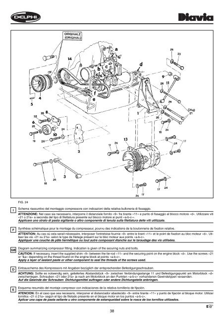
FIG. 24<br />
I<br />
F<br />
GB<br />
D<br />
E<br />
Schema riassuntivo del montaggio compressore con indicazioni della relativa bulloneria di fissaggio.<br />
A<strong>TT</strong>ENZIONE: Nel caso sia necessario, interporre il distanziale fornito «9» fra tirante «11» e punto di fissaggio al blocco motore «d». Utilizzare viti<br />
«21 o 21a» a seconda del tipo di filettatura presente sul blocco motore ai punti «a-b-c-».<br />
Applicare uno strato di pasta sigillante o altro componente di tenuta sulla filettatura delle viti utilizzate.<br />
Synthèse schématique pour le montage du compresseur, pourvu des indications de la boulonnerie de fixation relative.<br />
A<strong>TT</strong>ENTION: Au cas où cela serait nécessaire, interposer l’entretoise fournie «9» entre le tirant «11» et le point de fixation au bloc moteur «d». Utiliser<br />
les vis «21 ou 21a» selon le type de filetage présent sur le bloc moteur aux points «a-b-c».<br />
Appliquer une couche de pâte hermétique ou tout autre composant étanche sur le taraudage des vis utilisées.<br />
Diagram summarizing compressor fitting. Indication is given of the securing nuts and bolts.<br />
CAUTION: If necessary, insert the supplied shim «9» between the tie-rod «11» and the securing point on the engine block «d». Use the screws «21<br />
or “&a» depending on the thread found on the engine block at points «a-b-c».<br />
Apply a layer of sealant paste or other component to seal the threads of the screws used.<br />
Einbauschema des Kompressors mit Angaben bezüglich der entsprechenden Befestigungsschrauben.<br />
ACHTUNG: Sollte es notwendig sein, geliefertes Abstandstück «9» zwischen Verbindungsstange 11 und Befestigungspunkt am Motorblock «d»<br />
zwischenlegen. Schrauben «21 oder 21a» je nach am Motorblock an den Punkten «a-b-c» vorhandenen Gewindetypen veraenden.<br />
Auf die Gewinde der Schrauben Dichtungsmittel auftragen oder andere Dichtungsteile anbringen.<br />
Esquema resumido del montaje compresor con indicaciones de la relativa tornillería de fijación.<br />
ATENCION: En el caso que sea necesario, interponer el distanciador abastecido «9» entre tirante «11» y punto de fijación al bloque motor. Utilizar<br />
tornillos «21 ó 21a» según el tipo de filetado presente en el bloque motor en los puntos «a-b-c».<br />
Aplicar una capa de pasta sellante u otro componente de estanqueidad sobre la rosca de los tornillos utilizados.<br />
38<br />
☞