variostar 247 variostar 317, 317-2 operating instructions ... - dpiaca
variostar 247 variostar 317, 317-2 operating instructions ... - dpiaca
variostar 247 variostar 317, 317-2 operating instructions ... - dpiaca
- No tags were found...

Create successful ePaper yourself
Turn your PDF publications into a flip-book with our unique Google optimized e-Paper software.
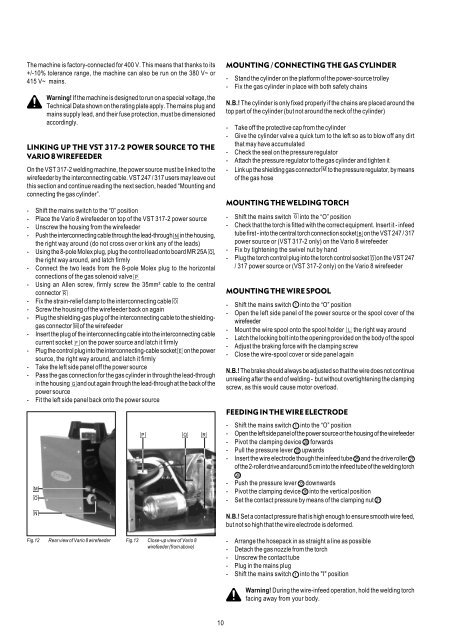
The machine is factory-connected for 400 V. This means that thanks to its+/-10% tolerance range, the machine can also be run on the 380 V~ or415 V~ mains.Warning! If the machine is designed to run on a special voltage, theTechnical Data shown on the rating plate apply. The mains plug andmains supply lead, and their fuse protection, must be dimensionedaccordingly.LINKING UP THE VST <strong>317</strong>-2 POWER SOURCE TO THEVARIO 8 WIREFEEDEROn the VST <strong>317</strong>-2 welding machine, the power source must be linked to thewirefeeder by the interconnecting cable. VST <strong>247</strong> / <strong>317</strong> users may leave outthis section and continue reading the next section, headed “Mounting andconnecting the gas cylinder”.- Shift the mains switch to the “0” position- Place the Vario 8 wirefeeder on top of the VST <strong>317</strong>-2 power source- Unscrew the housing from the wirefeeder- Push the interconnecting cable through the lead-through in the housing,the right way around (do not cross over or kink any of the leads)- Using the 8-pole Molex plug, plug the control lead onto board MR 25A ,the right way around, and latch firmly- Connect the two leads from the 8-pole Molex plug to the horizontalconnections of the gas solenoid valve- Using an Allen screw, firmly screw the 35mm² cable to the centralconnector- Fix the strain-relief clamp to the interconnecting cable- Screw the housing of the wirefeeder back on again- Plug the shielding-gas plug of the interconnecting cable to the shieldinggasconnector of the wirefeeder- Insert the plug of the interconnecting cable into the interconnecting cablecurrent socket on the power source and latch it firmly- Plug the control plug into the interconnecting-cable socket on the powersource, the right way around, and latch it firmly- Take the left side panel off the power source- Pass the gas connection for the gas cylinder in through the lead-throughin the housing and out again through the lead-through at the back of thepower source- Fit the left side panel back onto the power sourceMOUNTING / CONNECTING THE GAS CYLINDER- Stand the cylinder on the platform of the power-source trolley- Fix the gas cylinder in place with both safety chainsN.B.! The cylinder is only fixed properly if the chains are placed around thetop part of the cylinder (but not around the neck of the cylinder)- Take off the protective cap from the cylinder- Give the cylinder valve a quick turn to the left so as to blow off any dirtthat may have accumulated- Check the seal on the pressure regulator- Attach the pressure regulator to the gas cylinder and tighten it- Link up the shielding gas connector to the pressure regulator, by meansof the gas hoseMOUNTING THE WELDING TORCH- Shift the mains switch into the “O” position- Check that the torch is fitted with the correct equipment. Insert it - infeedtube first - into the central torch connection socket on the VST <strong>247</strong> / <strong>317</strong>power source or (VST <strong>317</strong>-2 only) on the Vario 8 wirefeeder- Fix by tightening the swivel nut by hand- Plug the torch control plug into the torch control socket on the VST <strong>247</strong>/ <strong>317</strong> power source or (VST <strong>317</strong>-2 only) on the Vario 8 wirefeederMOUNTING THE WIRE SPOOL- Shift the mains switch into the “O” position- Open the left side panel of the power source or the spool cover of thewirefeeder- Mount the wire spool onto the spool holder the right way around- Latch the locking bolt into the opening provided on the body of the spool- Adjust the braking force with the clamping screw- Close the wire-spool cover or side panel againN.B.! The brake should always be adjusted so that the wire does not continueunreeling after the end of welding - but without overtightening the clampingscrew, as this would cause motor overload.FEEDING IN THE WIRE ELECTRODE- Shift the mains switch into the “O” position- Open the left side panel of the power source or the housing of the wirefeeder- Pivot the clamping device forwards- Pull the pressure lever upwards- Insert the wire electrode though the infeed tube and the drive rollerof the 2-roller drive and around 5 cm into the infeed tube of the welding torch- Push the pressure lever downwards- Pivot the clamping device into the vertical position- Set the contact pressure by means of the clamping nutN.B.! Set a contact pressure that is high enough to ensure smooth wire feed,but not so high that the wire electrode is deformed.Fig.12 Rear view of Vario 8 wirefeeder Fig.13 Close-up view of Vario 8wirefeeder (from above)- Arrange the hosepack in as straight a line as possible- Detach the gas nozzle from the torch- Unscrew the contact tube- Plug in the mains plug- Shift the mains switch into the "I" positionWarning! During the wire-infeed operation, hold the welding torchfacing away from your body.10