Stufa 555 T C/MK per rivestimenti COSTELLAZIONI Kaminofen 555 ...
Stufa 555 T C/MK per rivestimenti COSTELLAZIONI Kaminofen 555 ...
Stufa 555 T C/MK per rivestimenti COSTELLAZIONI Kaminofen 555 ...

You also want an ePaper? Increase the reach of your titles
YUMPU automatically turns print PDFs into web optimized ePapers that Google loves.
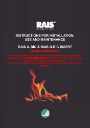
DIMENSIONI c UNO ANTA150571293519,5VISTA POSTERIOREVERSIONE A PARETE78O 2039 393278VISTA POSTERIOREVERSIONE CENTROSTANZADIMENSIONI c UNO SALISCENDI150571293519,5O207839 39VISTA POSTERIOREVERSIONE A PARETE3178VISTA POSTERIOREVERSIONE CENTROSTANZA7
DIMENSIONI c DUE ANTAØ182928158Ø1880401357134158Ø188040135713418SEMITRANCIO Ø8.879DIMENSIONI c DUE SALISCENDIØ1818SEMITRANCIO Ø8.8798
CARATTERISTICHE E DATI TECNICIDati tecnici• Combustibile Legno o lignite secondo DIN 51731• Interno Monoblocco <strong>555</strong> T C/<strong>MK</strong> Focolare in Aluker ®• Piano fuoco in ghisa• Cassetto cenere• Registro aria primaria• Cappa in ghisa girevole• Raccordo in ghisa <strong>per</strong> cappa girevole• Uscita fumi dal lato posteriore, su<strong>per</strong>iore• Su<strong>per</strong>ficie focolare: 1100 cm²• Volume del focolare: 660 dm³• Su<strong>per</strong>ficie della bocca fuoco: 1880 cm²• Anta con vetro ceramico resistente fino a 750 °C• Deflettore fumi su<strong>per</strong>iore• Deflettore fumi inferiore inclinato• Mantello cappa• Kit ventilazione Multifuoco® (optional)• Piedini regolabili (10 cm)Per la misurazione della canna fumaria secondo le normative DIN 4705 sono validi i dati seguenti.c UNOversioneAntac UNOversioneSaliscendic DUEversioneAntac DUEversioneSaliscendi• Consumo orario nominale kg/h 2.3 2.3 2.3 2.3• Potenza nominale Kw 7 7 7 7• Capacità di riscaldamento m³ 56-144 56-144 56-144 56-144• DIN Bauart A1 A1 A1 A1• N° prova DIN 18891 Prüfbericht Nr. FSP-Wa 1380 FSP-Wa 1380 RB BF1-Hn 1167 FSP-Wa 1380• N° registrazione DIN PLUS: - - P 02 XXM 11 -• Diametro scarico Cm ∅18 ∅18 ∅18 ∅18• A<strong>per</strong>tura focolare Cm 40x39 40x39 40x39 40x39• Peso dell’interno conkg ca. 290 320 200 230rivestimentoDati di funzionamento con camera di combustione chiusa (Valore medio <strong>per</strong> legno e briketts di legno)c UNOc DUEPotenza nominale 7 kWFlusso fumi 7 g/sTemp. Media nel tubo di scarico del gas 260 °CPressione min. d’asportazione della capacità calorica 0.11 mbarLa potenza nominale della stufa è in grado di soddisfare le seguenticondizioni:c UNOc DUE7 kW- favorevoli 144 m 3- un po’ meno favorevoli Condizioni sufficienti <strong>per</strong> 84 m 3- non favorevoli 56 m 3I valori sopraindicati della capacità calorica <strong>per</strong> stanza sono secondo la normativa DIN 18893 <strong>per</strong> stanze che nonsono costruite secondo le normative <strong>per</strong> il risparmio calorico.Per stanze che sono costruite secondo le normative <strong>per</strong> il risparmio calorico, sono necessarie capacità caloricheminori.13
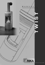
ESPLOSO FOCOLARE INTERNO <strong>555</strong> 04 T C/<strong>MK</strong> ANTA16110234531112131417615187891920212223Nr. Descrizione Codice Nr. Descrizione Codice1 Perno L=61 510 A/51 04 E03031000 13 Laterale posteriore <strong>555</strong>/57 Aluker E060309202 Perno cerniera anta 510 A/51 04 E03031010 14 Laterale anteriore <strong>555</strong>/57 Aluker E060309103 Bussola guida <strong>per</strong> tubo molla E03010140 15 Griglia p/piano 500 200x200 E050200104 Tubo protezione molla E02030810 16 Mantello cappa <strong>555</strong> 04 -5 Molla <strong>per</strong> cerniera E03021560 17 Monoblocco saldato <strong>555</strong> 04 -6 Perno fermo molla 510 A/51 04 E03031020 18 Registro aria 510 D920311107 Anta montata <strong>555</strong> T/57 04 G02010960 19 Rondella 10x21 Acciaio Zincata F010503108 Cassetto cenere 170x170x100 G01080020 20 Rondella 6x14 Acciaio Zincata F010500509 Piano fuoco <strong>555</strong> T 387x388 E05010540 21 Dado esagonale M6 zincato F0104005010 Deflettore fumi su<strong>per</strong>iore E01082460 22 Dado esagonale M16 zincato F0104013011 Deflettore fumi inferiore E01082470 23 Piedino M16 L=180 E0114041012 Schienale <strong>555</strong>/57 Aluker 234x600 E0603090015
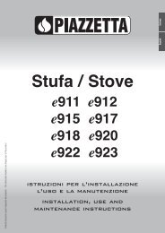
ESPLOSO FOCOLARE INTERNO <strong>555</strong> T C/<strong>MK</strong> SL9 10 11 1287654321311415Nr. Descrizione Codice1 Vetro R 300 ARCO = 526 H = 478 E060112202 Anta montata <strong>555</strong>T/57 G020107203 Piano fuoco <strong>555</strong> T 387x388 verniciato E050105404 Cassetto cenere 170x170x100 500 G010800205 Griglia p/piano 500 200x200 verniciata E050200106 Laterale anteriore <strong>555</strong>/57 Aluker 115x600 E060309107 Laterale posteriore <strong>555</strong>/57 Aluker 151x600 E060309208 Schienale <strong>555</strong>/57 Aluker 234x600 E060309009 Deflettore fumi inferiore vern. 270x442x70 E0108247010 Deflettore fumi su<strong>per</strong>iore vern. 460x333x5 E0108246011 Cappa girevole ø320 E0506066012 Raccordo scarico fumi ø180 510 E0506065013 Monoblocco saldato <strong>555</strong> 04 /14 Dado esagonale M16 zincato F0104013015 Piedino M16 L=180 E0114041016
COLLEGAMENTO ALLA CANNA FUMARIANote generichePrima di procedere con il montaggio scegliere la posizione dove verrà installata la stufa, quindi, determinatal‘altezza dei tubi di collegamento praticare il foro alla canna fumaria e, posizionare il rosone a muro, tenendopresente le altezze da terra come indicato nelle figure.Per il collegamento di stufe al camino si possono usare al massimo due curve, con cambio di direzione >=90°, elunghezza del canale da fumo in proiezione orizzontale non su<strong>per</strong>iore a 2 m.I raccordi devono essere il più brevi possibili, privi di strozzature e spigoli interni, realizzati in materiali resistenti allacorrosione dei fumi e a tem<strong>per</strong>ature di 550-600° C.SI SI NOMAX 2 MIl collegamento alla canna fumaria deve avvenire in conformità a quanto indicato al punto NORME GENERALIPag.10 e con le norme in vigore nel luogo di installazione, <strong>per</strong> consentire un corretto smaltimento dei fumi econseguente buon funzionamento della stufa.Per il collegamento alla canna fumaria, si consiglia di usare tubi e curve del GRUPPO PIAZZETTA S.p.A., inquanto lo scarico fumi del prodotto è dimensionato <strong>per</strong> l‘innesto di questi, inoltre le curve sono dotate d’ispezioneche consentono il controllo, la pulizia, e la manutenzione su tutti gli interventi dell‘impianto.Possono essere applicati anche altri tubi, previo adeguamento o compatibilità del manicotto d‘inserimento. In talecaso <strong>per</strong>ò il GRUPPO PIAZZETTA S.p.A. assicura il buon funzionamento solo <strong>per</strong> quanto di sua produzione edimpiegato secondo le sue specifiche.Se si dovesse realizzare un disassamento con delle curve si consiglia di prestare attenzione, in quanto ilcollegamento eseguito potrebbe non avere la facoltà di reggere il peso soprastante, e potrebbe richiedere deisistemi di supporto adeguati.Rispettare la distanza min. di 40 cm su elementi di costruzione sensibili alle alte tem<strong>per</strong>ature (rivestimento).Nel raggio di 200 mm dal muro non ci devono essere materiali infiammabili o sensibili al calore.Nel caso contrario, sostituire con materiali secondo le normative DIN 18160 seconda parte, paragrafo 5.1.4.Controllare che i vari pezzi del tubo siano bene innestati con la stufa e la canna fumaria. Controllare che il tubo nonentri troppo all’interno della canna fumaria.17
Scarico fumi posterioreIl collegamento avviene all’interno del rivestimento ruotandol’apposito raccordo della cappa in ghisa ed uno spezzone ditubo, la cui lunghezza dipende dalla posizione della cannafumaria.Praticato il foro <strong>per</strong> l’allacciamento con altezza da terrariportata in figura, fissare se previsto il rosone a muro, tagliarelo spezzone di tubo ( la misura risulta pari alla quota B più laparte da incassare nel muro) dalla parte del bicchiere, edinserirlo nella canna fumaria fino ad avere una sporgenzaminima <strong>per</strong> la presa, sigillare dove necessario.Quote in cm (vedi figure a lato)C UNOC DUEA 129 134B Vers. Anta 40 38B Vers. Saliscendi 39 37C 140 145D Vers. Anta 52 49D Vers. Saliscendi 51 48E 20 20Hparagrafo seguenteScarico fumi su<strong>per</strong>ioreL’allacciamento si differenzia dal precedente solo <strong>per</strong> il fattoche non rimane all’interno del rivestimento e non richiede larotazione del raccordo della cappa in ghisa.La quota H riportata nelle figure qui a lato, varia a seconda deitubi di raccordo.Per esempio se si usano un tubo da metro, con registroTR100 ed una curva C6 con diametro 18 (misure diingombro cm 32x32) risulta H = (100–5) + (32–9) = 118 cmdove (100 – 5) è la lunghezza del tubo meno il bicchiere, e(32 – 9) è l’ingombro della curva meno metà diametro , cioè laquota tra asse e bordo inferiore della curva.Se invece del TR100 si usassero due tubi da 50 cm laquota risulterebbe inferiore di altri 5 cm circa, in quanto siavrebbe un ulteriore innesto.ATTENZIONE: le misure riportate nelle figure sono indicativein quanto prevedono un pavimento ed una parete regolari, <strong>per</strong>cui si può riscontrare una certa differenza.ATTENZIONE: i tubi vanno collegati con il bicchiere rivolto verso il basso.18
UTILIZZO DEL MANTELLO CAPPAIl monoblocco <strong>555</strong> T C/<strong>MK</strong> dispone di un’intercapedine interna, all’interno della quale circola l’aria che riscaldal’ambiente.L’aria dell’ambiente può essere riscaldata in due modi diversi descritti nei due paragrafi seguenti.Mantello cappaMonobloccoRivestimentoSemitranciFlussoaria convettivaPresa aria esternaFigura 1: Circolazione aria convettivaFigura 2: Semitranci mantello cappaSistema a convezione naturaleLa diffusione del calore avviene mediante la circolazione spontanea di masse d’aria calda. Aria pulita e ricca diossigeno viene fatta fluire in ambiente attraverso la griglia di presa aria esterna, posta normalmente nel muroretrostante la stufa. L’aria ambiente miscelata con l’aria della presa aria esterna entra nell’intercapedine delrivestimento tramite la bocchetta aria del rivestimento. L’aria passando attorno al focolare dove si riscalda e, <strong>per</strong>moto naturale, si propaga all’ambiente in modo spontaneo, attraverso la canalizzazione del mantello cappa (vediFigura 1).Se si volesse applicare il sistema a convezione naturale si deve, tramite l’utilizzo di un cacciavite, togliere isemitranci posti sul mantello cappa facendo leva su di essi (vedi Figura 2).Sistema Multifuoco system®Il monoblocco è predisposto <strong>per</strong> l’installazione del Kit di ventilazione (optional).Una più efficace azione riscaldante può essere ottenuta accelerando i moti convettivi naturali mediante l’azione diun ventilatore. L’applicazione del Kit di ventilazione <strong>per</strong>mette di amplificare l’azione riscaldante dell’aria, cheforzata, circola più velocemente e si spinge più lontano dalla fonte di calore. La funzione del ventilatore è quella diaspirare l’aria calda, che notoriamente ristagna in alto miscelandola con aria ossigenata proveniente dalla presaaria esterna, facendola passare attraverso apposite feritoie poste in alto alla stufa, l’aria, attraverso lacanalizzazione del mantello cappa viene confluita attorno al focolare riscaldandosi ulteriormente, indirizzandola allabocchetta posta nella parte inferiore della stufa.Se si volesse applicare il sistema Multifuoco system® NON si devono togliere i semitranci posti sul mantello cappa(vedi Figura 1).Per l’installazione del Kit ventilazione MULTIFUOCO SYSTEM® seguire le istruzioni allegate allo stesso.19
Distanze minime di sicurezzaZONA PERICOLOSA PER IRRAGGIAMENTOParete posterioreAParete laterale<strong>Stufa</strong>Protezione a pavimentoZona radianteCon riferimento alla figura su<strong>per</strong>iore, le distanze minime di sicurezza da materiali sensibili al calore o infiammabilicosì come da muri portanti e altre pareti è di:ABC20 cm dalla parete posteriore alla stufa20 cm dalla parete laterale100 cm nella zona radianteNel caso di pavimentazione sensibile al calore o infiammabile è necessario usare una protezione <strong>per</strong> il pavimento(<strong>per</strong> es. lastra di lamiera d’acciaio), marmo o piastrelle. Le misure minime sono:DE50 cm30 cm (misurato dallo spigolo interno dell’a<strong>per</strong>tura del focolare)In generale• Assicurarsi che nella stanza in cui viene installata ci sia una aerazione sufficiente (vedi paragrafo Presa d’ariaesterna).• Tenere qualsiasi prodotto infiammabile ben lontano dalla stufa durante il suo funzionamento (MINIMO: 100 cmdalla parete frontale).• Durante il funzionamento la porta deve rimanere chiusa, altrimenti si può danneggiare l’interno del focolare.20
PRELIMINARI ALL’INSTALLAZIONEPRIMA DI INSTALLARE IL MONOBLOCCO E RIVESTIMENTO1. Prima di procedere all’installazione del prodotto leggere attentamente tutte le informazioni riportate nelcapitolo NORME GENERALI.2. Eseguire la presa d'aria esterna rispettando l'indicazione riportata nel capitolo NORME GENERALI.3. Sballare il monoblocco, togliere il fissaggio del piano fuoco svitando il dado ad alette.4. Togliere tutti i polistiroli che bloccano i deflettori;5. Inserire i piedini sul monoblocco avvitando prima allo stesso il dado esagonale in dotazione.6. Regolare l'altezza del piano fuoco del monoblocco da terra bloccando i piedino con il controdado.7. Svitare le due viti ai lati <strong>per</strong> sbloccare i contrappesi e l’anta saliscendi (Fig. 3). Questa o<strong>per</strong>azione vaeffettuata PRIMA DI INSTALLARE IL RIVESTIMENTO.VITI DI FISSAGGIODA SVITARE AI LATIDEL MONOBLOCCOFigura 3: Sblocco dei contrappesiFigura 4: Installazione collari8. Nel monoblocco se si desidera effettuare la canalizzazione dell’aria convettiva nella parte su<strong>per</strong>iore ènecessario avvitare appositamente i collari forniti nella confezione accessori. (Fig. 4).Il monoblocco è corredato di piedini regolabili che <strong>per</strong>mettono di portare l'altezza del bordo esterno da minimo 35cm ad un massimo di 45 cm. Per altezze su<strong>per</strong>iori, è necessario inserire alcuni spessori sotto i piedini.21
USOPrecauzioni da mantenere durante il funzionamento della stufa Tenete assolutamente lontano i bambini dal focolare; Non mettete MAI prodotti infiammabili (alcool, solventi, elementi in legno, etc.) vicino al focolare (cioè ad unadistanza inferiore ad 100 cm, vedi capitolo ZONA PERICOLOSA PER IRRAGGIAMENTO); Aprite la porta della stufa con l'accessorio di cui è fornito (guanto); Non state a lungo esposti all'irraggiamento della stufa a distanze inferiori ad 100 cm: avvicinatevi solo <strong>per</strong> iltempo necessario <strong>per</strong> la carica di combustibile. Restare <strong>per</strong> un tempo prolungato vicino al focolare puòessere causa di scottature. Utilizzate come combustibile solo legna, possibilmente con tenori di umidità inferiore a 20% sulla massa. Prima dell'accensione, assicuratevi sempre che non ci siano elementi infiammabili ed esplosivi sul pianofuoco o sotto di esso (<strong>per</strong> esempio bombolette spray, alcool, etc) tranne la legna;Regole d’uso fondamentaliNonostante i tipi d'impianto siano diversi, alcune importanti istruzioni possono essere d'aiuto <strong>per</strong> evitare l'emissionedi fumi inquinanti.La pezzatura del materiale da bruciare influenza in modo determinante il contenimento delle emissioni dell'impiantotermico, infatti una maggiore su<strong>per</strong>ficie del combustibile favorisce l'andamento della combustione e lo stesso dicasi<strong>per</strong> la secchezza, la disgregazione termica e la liberazione del gas.Per l'accensione deve essere usata legna minuta. Se si usa legna di grossa pezzatura la combustione inizia solotardivamente. Nella conduzione del caminetto bisogna inoltre badare che all'avviamento il focolare non sia troppopieno. Quando poi la combustione è avviata, è meglio aggiungere di frequente piccole quantità di combustibile chegrandi quantità a distanza di tempo. (vedi paragrafo Ricarica).Altrettanto importante è un apporto d'aria sufficiente, soprattutto nella fase di accensione. La combustionedovrebbe venir regolata da un apporto dosato di combustibile ed aria.La combustione è buona se:• dalla stufa non escono fumi visibili;• le ceneri sono di colore grigio o bianco;• c'è poca fuliggine nella canna fumaria e nel focolare;• il consumo di combustibile è contenuto.I principali presupposti <strong>per</strong> una combustione ecologica della legna sono:• utilizzare solo legna secca;• assicurare una tem<strong>per</strong>atura elevata nella camera di combustione, possibilmente in tutte le fasi di carico;• mantenere un giusto apporto d’aria durante la combustione;• all'accensione non sovraccaricare la camera di combustione;Una cattiva combustione è caratterizzata da:• emissione di fumi molto densi;• fumo di colore giallo o grigio scuro;• odore sgradevole, dovuto a sostanze inquinanti;• cenere molto scura;• imboccatura nera del comignolo;• elevato consumo di combustibile.22
Prima accensione Estrarre dal focolare del monoblocco tutta la documentazione allegata e gli accessori. Leggere attentamente le istruzioni d’uso.Per la prima accensione del focolare, o anche nel caso non sia stato usato <strong>per</strong> lungo tempo, usare pococombustibile (tutti i materiale devo adattarsi al calore), in quanto potrebbero sprigionarsi degli odori dovutiall'evaporazione delle vernici o dei grassi. Per ovviare il problema è sufficiente aerare il locale.Regolazione dell’aria comburenteLa stufa è dotata di un registro che <strong>per</strong>mette la regolazione del flusso di aria comburente denominata primaria chedetermina la resa termica del monoblocco. Pertanto fare attenzione alle posizioni qui sotto elencate:+Posizione “+” aria comburente: usare solo nelle fasi diaccensione eriscaldamento.-Posizione “-” aria comburente: usare solo nella fase diresa termica nominale emantenimento brace.Figura 3: Regolazione aria primariaAccensioneNella fase di accensione il focolare dovrà essere portato velocemente alla tem<strong>per</strong>atura di esercizio. Qualora questovenisse lentamente, sarà inevitabile la formazione di condensa e il vetro si sporcherà.Caricare il focolare con le quantità di combustibile e con le modalità come riportato di seguito:1. Posizionare il registro di regolazione dell’aria primaria nella posizione “+” (posizione massima) usaresolo nelle fasi di accensione e riscaldamento.2. Porre al centro del focolare del materiale <strong>per</strong> accendere (carta, accendifuoco, etc.) unire in forma dipiramide piccoli pezzi di legna tenera (abete). Aggiungere successivamente dopo che la legna di piccolidimensioni sarà arsa completamente aggiungere 2 – 3 ceppi di piccole dimensioni di legna dura (faggio,quercia, betulla).3. Per una rapida accensione della legna tenere la portina a<strong>per</strong>ta ca. 2 cm. <strong>per</strong> 5 – 10 min.23
Funzionamento e resa termica nominale1. Formatasi sufficientemente brace portare il registro di regolazione dell’aria primaria nella posizione di resatermica nominale (vedi Figura 3).2. Caricare il focolare con la quantità di combustibile come riportato nella seguente Tabella 1.3. Appena si è sviluppata la fiamma chiudere la porta.4. Nel caricare la legna non aprire la porta in modo brusco altrimenti possono fuoriuscire gas di scarico,usando sempre il guanto in dotazione.Tabella 1: Quantità di combustibileVersione Numero di ceppi Quantità [kg]c UNO / c DUE 2 1.73A<strong>per</strong>tura della portaDurante il funzionamento la porta deve rimanere chiusa, altrimenti si può danneggiare l’interno del focolare.L'a<strong>per</strong>tura della porta va fatta lentamente, tenendola <strong>per</strong> qualche secondo leggermente scostata dall'insertoprima della completa a<strong>per</strong>tura. Aprire la porta quando la fiamma è smorzata o comunque mai quando ètroppo intensa, ed usare sempre il guanto in dotazione.Fate attenzione che la porta autochiudente non si chiuda con violenza, <strong>per</strong>ché si potrebbe rom<strong>per</strong>e il vetro.ATTENZIONE: IL GUANTO NON È FATTO PER POTER PRENDERE IN MANO LE BRACI !!!Nel caso durante l'alimentazione fuoriuscisse del fumo, ciò non comporta alcun <strong>per</strong>icolo; aprire momentaneamentela finestra.RicaricaIl focolare dell’apparecchio è provvisto di un piano fuoco, strutturato <strong>per</strong> la carica di un solo strato di legna.1. Aggiungere ceppi di legna ogni 45/60 minuti.2. Nel caricare la legna non aprire la porta in modo brusco altrimenti possono fuoriuscire gas di scarico,usando sempre il guanto in dotazione.3. Distribuire uniformemente sul piano fuoco in ghisa le braci ed aggiungere max 2 – 3 ceppi di legna (<strong>per</strong>quantità vedi Tabella 1: Quantità di combustibile)4. Utilizzare solo legna secca, né rifiuti, né legno multistrati.5. Appena si è sviluppata la fiamma chiudere la porta.ATTENZIONE: NON SOVRACCARICARE LA STUFA. SUPERANDO LE QUANTITÀ INDICATE DI SEGUITO, NON SOLOVARIANO IL RENDIMENTO E LE EMISSIONI INQUINANTI, MA LA STUFA PUÒ SURRISCALDARSI PROVOCANDO DANNIANCHE ALL'EDIFICIO. RISPETTATE, QUINDI, LE QUANTITÀ DI CARICO PREVISTE.Nei caminetti versione saliscendi (SL) <strong>per</strong> la ricarica sfruttare solamente l’a<strong>per</strong>tura saliscendi (ovveroalzare ed abbassare il vetro) e non l’a<strong>per</strong>tura ad anta.Funzionamento notturnoUtilizzando un legno abbastanza duro, se il vento e le condizioni di tiraggio sono ragionevolmente stabili, ilcaminetto continuerà a bruciare <strong>per</strong> alcune ore durante la notte.L'ultima cosa da fare alla sera è assicurarsi che il letto di braci sia ridotto ma vivo ed aggiungere combustibileprima di chiudere la porta e ridurre l’alimentazione dell'aria (Figura 3).24
Funzionamento durante stagioni intermedieDurante le stagioni intermedie, quando le tem<strong>per</strong>ature esterne sono più alte, un brusco rialzo può provocare unmalfunzionamento del tiraggio impedendo una corretta uscita dei fumi. In tal caso il focolare dovrà essere caricatocon poca legna, aprendo il registro dell’aria primaria, in modo tale che il combustibile presente arda piùvelocemente (generando la fiamma) e stabilizzando così il tiraggio. Per evitare che si creino controcorrenti nel lettodi brace, la cenere deve essere attizzata più spesso e con attenzione.Smaltimento delle ceneriIl cassetto cenere deve essere svuotato regolarmente, in modo da impedire che la cenere arrivi alla griglia delfocolare <strong>per</strong>ché potrebbe danneggiarlo.Le ceneri devono essere poste in un contenitore in metallo con co<strong>per</strong>chio a tenuta. Fino allo spegnimento definitivodelle ceneri, il contenitore chiuso deve essere posto su una base non combustibile o terra e ben lontano damateriali combustibili.ATTENZIONE: LA CENERE MANTIENE A LUNGO LA BRACE ACCESA !!!Surriscaldamento e sicurezzaDurante il funzionamento, alcune parti della stufa (porta, maniglia, registro) possono raggiungere tem<strong>per</strong>atureelevate.Ricordarsi di mantenere le distanze di sicurezza precedentemente indicate.Fate dunque molta attenzione ed usate le dovute precauzioni e seguite sempre le istruzioni.Quando poi dovete ricaricare di legna il focolare o regolare l'afflusso d'aria, usate il guanto in dotazione.Se durante l'alimentazione una parte della stufa diviene rossa, significa che è surriscaldato.Interrom<strong>per</strong>e immediatamente l'alimentazione. Chiudere la porta ed i registri aria controllando che il rossorediminuisca.Se durante il funzionamento, qualsiasi parte della stufa o del tubo di uscita fumi <strong>per</strong>desse fumo, bloccareimmediatamente l'alimentazione sia di aria che combustibile come indicato sopra; quindi una volta raffreddatocontrollare il motivo della <strong>per</strong>dita e se necessario chiamare <strong>per</strong>sonale specializzato del rivenditore. Nel frattempoaerare il locale.25
CombustibilePossono essere usati i seguenti materiali da combustione: legno (Faggio o Betulla) così come Briketts di legnosecondo la normativa DIN 51731, classe di misura HP2.Usare soltanto questi materiali <strong>per</strong> la combustione. Non usare mai legno umido o legno con pece.Inoltre non possono essere usati scarti (immondizie), legno verniciato o legni impellicciati con materiale sintetico,<strong>per</strong>ché potrebbero danneggiare la stufa, la canna fumaria e non come ultimo inquinare la natura.Le caratteristiche del legno o combustibile usato (umidità; dimensioni; densità) influiscono sulla qualità dellacombustione. Per questo è importante conoscere la tipologia della legna.Riportiamo qui di seguito alcune informazioni in merito.Solitamente la legna da ardere viene suddivisa in due categorie: legna forte e legna dolce.Le caratteristiche della legna forte sono rappresentate da un legno duro e pesante, fornendo al focolare unafiamma sostenuta e <strong>per</strong>sistente.Le caratteristiche del legno dolce sono rappresentate da un legno tenero e leggero, fornendo al focolare unafiamma si vivace ma di breve durata, il che a parità di potenza, comporta un consumo su<strong>per</strong>iore. Un’altracaratteristica di alcuni tipi di legno dolce è che possono essere resinosi, presentando quindi diversi inconvenientialla combustione. Per esempio: fuliggine consistente; poca brace; particelle incandescenti; scoppiettii; richiesta diuna pulizia più frequente alla canna fumaria e alla stufa.Il funzionamento ottimale del caminetto è ottenuto dalla combustione di legna asciutta con un contenuto massimodi acqua del 20% del suo peso. A tal fine, si consiglia di immagazzinare la legna in un luogo ventilato <strong>per</strong> due annicirca. Legno troppo umido brucia senza fiamma, è causa di molta cenere, elevata quantità di creosoto (catrame +condensa dovuta al vapore contenuto nei fumi), quindi creazione di incrostazioni sulla canna fumaria oltre cheriduzioni di tiraggio. Le dimensioni ottimali della legna sono costituite da una lunghezza pari a 20 cm ed un<strong>per</strong>imetro della sezione compresa tra 30 e 35 cm.Avvertenza: la combustione di residui di plastica, imballaggi, di legno verniciato o trattato e di qualsiasi altro materialediverso dal legno naturale è in violazione alle norme sul contenimento delle immissioni <strong>per</strong>icolose nell'atmosfera oltre chedanneggiare il caminetto e la canna fumaria. Sterpi, carta e legna piccola possono essere utilizzati SOLO <strong>per</strong> l'accensione.ATTENZIONE: NON UTILIZZARE MAI PRODOTTI FACILMENTE INFIAMMABILI COME BENZINA, ALCOOL, ETC; ANZI,CONSERVATELI LONTANO DAL CAMINETTO.LEGNA FORTELEGNA DOLCEAcero campestre Marasco selvatico Ailanto Pioppo tremoloAlloro Nocciolo Bagolaro SaliconeBetulla* Noce comune Carrubo SambucoCarpino bianco Olivo Castagno TiglioCarpino nero Olmo siberiano* CipressoCerro Pero CornioloCiliegio Pesco selvatico GelsoFaggio Platano Ontano napoletanoFrassino Pruno selvatico Ontano neroLeccio Robinia OrnielloMaggiociondolo Roverella Pioppo cipressino26
Potere calorifico(KW h/dm³ w=20%)10.50FAGGIO BIANCOROBINIAQUERCIAFRASSINOFAGGIOBETULLALARICEPINOPIOPPOTipologia legnamiONTANOSALICEABETE BIANCOABETE ROSSOValori indicativi riferiti ad 1°decimetro cubo di legna di forma omogenea con una <strong>per</strong>centuale di umidità (W) di circa 20%.• Per quanto sopra citato si consiglia di bruciare latifoglie forti (Faggio, Betulla, Quercia, ecc.) tenendopresente le indicazioni al paragrafo “Ricarica”. E’ ammesso anche l’uso di lignite.• Si consiglia inoltre di non bruciare: la carta straccia; le bricchette di carta; i rifiuti; il legno laccato o rivestito dilaminati plastici; il legno compensato o truciolare; i pannelli fibrosi; il legno trattato con prodotti protettivi; gliimballaggi; <strong>per</strong>ché potrebbero danneggiare la stufa e la canna fumaria.L'umidità influisce in modo notevole sulla qualità della combustione, <strong>per</strong>ché l'acqua nella legna abbassa latem<strong>per</strong>atura della combustione. Quindi come si vede dalla tabella sottostante all’aumentare dell’umidità diminuisceil potere calorifico.Ciò non solo può portare a più elevate emissioni di fumi, ma indica anche un pessimo utilizzo del combustibile acausa del diminuito potere calorifico. Inoltre, <strong>per</strong> la comparsa di condense, parti dell'impianto e le condutture deifumi possono subire danni; si deve <strong>per</strong>ciò bruciare solo legna secca.Per questo è importante anche l’accatastamento e la conservazione della legna in un luogo asciutto e arieggiato, el’uso dopo almeno 2 anni dal taglio.PERCENTUALE Tempo diPOTERE CALORIFICO DELLA LEGNA (Faggio)DI UMIDITA’ (W) stagionatura kWh/Kg Kcal/Kg kWh/dm³20 dopo 2 anni 4 3400 2.930 dopo 1 anni 3.4 2900 2.840 dopo 6 anni 2.8 2410 2.7Valori indicativi27
MANUTENZIONETutte le o<strong>per</strong>azioni di manutenzione (pulizia, eventuali sostituzioni, ecc...) vanno effettuate a fuoco spentoe quando il monoblocco è freddo. Inoltre non usare in nessun caso sostanza abrasive.Cassetto cenereIl cassetto cenere (vedi pag. 15) che si trova sotto la griglia deve essere svuotato ogni qualvolta si riempie,altrimenti ostruisce il passaggio dell'aria di alimentazione.ATTENZIONE: NON SVUOTARE IL CASSETTO CON CENERE CALDA.ANCHE SE IL FUOCO NEL CAMINETTO SIESTINGUE ALLA SERA, È POSSIBILE CHE TROVIATE LA CENERE CALDA IL MATTINO DOPO: QUINDI, FATEATTENZIONE A NON SVUOTARE LA CENERE ANCORA CALDA SU MATERIALE INFIAMMABILE OPPURE CHE POSSAESSERE DANNEGGIATO DA TEMPERATURE RELATIVAMENTE ALTE.Pulizia della canna fumaria e della stufaLa combustione della legna (soprattutto se con <strong>per</strong>centuali di umidità su<strong>per</strong>iori al 30%) dà origine al creosoto che,con l'andar del tempo, forma incrostazioni che occludono la canna fumaria ostruendo il passaggio dei fumi e che,essendo infiammabile, può incendiarsi provocando danni sia alla canna fumaria che alla struttura dell'abitato.ATTENZIONE: PER LA VOSTRA SICUREZZA, ALL'INIZIO, FATE ISPEZIONARE DA PERSONALE AUTORIZZATO IRACCORDI E LA CANNA FUMARIA UNA VOLTA OGNI DUE MESI. QUINDI, CON L'USO DELLA STUFA SAPRETE CONPIÙ PRECISIONE LA CADENZA DEGLI INTERVENTI MANUTENTIVI DA EFFETTUARSI SULL'IMPIANTO DI SCARICO FUMI.COMUNQUE, LA MANUTENZIONE ANNUALE È OBBLIGATORIA.Pulizia del vetroLa stufa è dotata di aria secondaria che ha anche la funzione di mantenere pulito il vetro.Per mantenerlo il più possibile pulito, evitare di utilizzare legna umida <strong>per</strong>ché il vapore acqueo si deposita sul vetrotrattenendo la fuliggine. Inoltre, è consigliabile posizionare la legna lontano dal vetro.Se dovesse rendersi necessario pulire il vetro:1. attendere che il focolare sia freddo;2. aprire l'anta ed utilizzare sul vetro prodotti sgrassanti a base di ammoniaca su un panno morbido o concarta da giornale. Non usare comunque materiali che possano graffiare o rovinare i vetri, in quanto legraffiature possono diventare crepe o rotture.Avvertenza: terminata la pulizia del vetro, assicuratevi sempre attentamente di chiudere bene l'antaLA PULIZIA SEL VETRO VA FATTA A FUOCO SPENTO ED IL VETRO DEVE ESSERE FREDDO.Nei caminetti versione saliscendi (SL) <strong>per</strong> la pulizia sfruttare l’a<strong>per</strong>tura del vetro ad anta aprendo ilchiavistello con la chiave in dotazione.28
Smontaggio dei deflettoriPer la pulizia del focolare ricordarsi di togliere anche i due deflettori fumi (vedi Figura 4). Per questa o<strong>per</strong>azione siconsiglia:SupportiDeflettore su<strong>per</strong>iore• Sollevare anteriormente il deflettoreinferiore e piegandolo da un lato fino atrovare la giusta inclinazioneabbassarlo cautamente verso il pianofuoco ed estrarlo, eseguire la stessaprocedura <strong>per</strong> il deflettore su<strong>per</strong>iore.• Quindi pulirli e rimontarli con l’ordineinverso.Deflettore inferioreFigura 4: Posizione dei deflettoriPulizia dell'aluker®.La parte interna del prodotto è costruito da un materiale di nuova concezione denominato “Aluker ® ”.L’ “Aluker ® ” è un materiale a base di sostanze assolutamente atossiche resistente al calore (fino a 1400°).Altra sua caratteristica importante è la buona resistenza meccanica; è comunque raccomandabile non gettare conforza legna di grosso taglio sulle piastre stesse.L’“Aluker ® ” durante l’accensione si annerisce, <strong>per</strong> poi tornare al colore naturale man mano che le piastre siriscaldano.Alcuni consigli <strong>per</strong> un buon utilizzo delle piastre in “Aluker ® ” sono:• Non gettare acqua <strong>per</strong> lo spegnimento del fuoco, lasciando che le piastre si raffreddino da sole;• Non graffiare le piastre in “Aluker ® ” con corpi metallici;Per la pulizia delle piastre in “Aluker ® ” usare un semplice scopino.Avvertenza: <strong>per</strong> la pulizia dell'Aluker®, non utilizzate mai corpi duri o graffianti.Sistema di chiusura automatico dell’antaATTENZIONE: QUESTA OPERAZIONE VA EFFETTUATA DA PERSONALE SPECIALIZZATO.Periodicamente, almeno ogni due anni, è necessario controllare il sistema di chiusura automatico dell’anta“saliscendi”, lubrificando in particolare modo le carrucole collocate all’interno della vetrocamera.29
Sostituzione della guarnizione della serranda registro aria (solo da <strong>per</strong>sonale autorizzato)Avvertenza: <strong>per</strong> questo intervento si consiglia di chiamare il rivenditore di zona.Se necessita la sostituzione della guarnizione della serranda registro aria:• togliere sotto il piano fuoco la protezione inferiore del monoblocco;• svitare i dadi della serranda;• sfilare le rondelle;• sfilare il registro aria;• sostituire la guarnizione.Per il montaggio proseguire a ritroso.DadoRondella piccolaRondella grandeRegistro ariaProtezioneinferioreRegistroariaDadociecoFigura 5: Sostituzione della guarnizione serrandaSostituzione del vetroAvvertenza: <strong>per</strong> questo intervento si consiglia di chiamare il rivenditore di zona.Il caminetto è dotato di un vetro ceramico spessore 4 mm, resistente ad uno shock termico di 750° C, questo puòessere rotto solamente a causa di un forte impatto o di un uso improprio.In caso di rottura sostituire il vetro solo con materiale originali.Per la sostituzione del vetro procedere come segue:• togliere l’anta (vedi paragrafo “Togliere l’anta”);• premunirsi di un paio di guanti anti-taglio;• togliere la guarnizione in cordone di fibravetro sul fermavetro;• svitare tutte le viti sui fermavetri;• togliere i fermavetri;• sostituire la guarnizione di fibravetro sul telaio anta;• montare il vetro nuovo inserendolo prima da un lato verticale e poi facendolo andare in appoggio negli appositisupporti nella parte inferiore del telaio anta;• sostituire la guarnizione tra fermavetri e vetro;• avvitare i fermavetri;• sostituire il cordone di fibravetro fissandolo con un filo di silicone appropriato.30
Togliere l’antaPer versione ad anta con sistema di chiusura esternoAvvertenza: <strong>per</strong> questo intervento si consiglia di chiamare il rivenditore di zona.Per togliere l’anta è sufficiente:• aprire l’anta;• in alto dal lato della cerniera dell’anta c’è un dispositivo che blocca l’anta in posizione a<strong>per</strong>ta, con l’ausilio di una chiave abrugola 3 mm lunga, allentare la vite e facendo una leggera forza spostarla verso la fine della corsa dell’asola (come èraffigurato in Figura 5);• bloccare nuovamente la vite;• svitare le viti della piastrina di regolazione, posizionate nella parte inferiore lato cerniera anta (vedi Figura 5);• fare una leggera flessione verso l’alto all’anta, facendo rientrare il <strong>per</strong>no;• trascinare l’anta nella parte inferiore verso l’esterno, (attenzione a non forzare in modo eccessivo il <strong>per</strong>no);• togliere l’anta;• <strong>per</strong> il montaggio procedere a ritroso, accertarsi che prima di inserire l’anta venga inserita sul <strong>per</strong>no inferiore dell’anta lospessore <strong>per</strong> porta prima della piastrina di regolazione.Avvertenza: l’o<strong>per</strong>azione di bloccaggio dell’anta non può e non deve essere fatta <strong>per</strong> altri utilizzi.Viti di fissaggio<strong>per</strong> il sistema dichiusuraVite <strong>per</strong> ilbloccaggiodell’antaPiastrina diregolazioneFigura 6: Smontaggio antaChiusura automatica dell’antaSe fosse necessario caricare il sistema di chiusura automatico anta:• togliere l’anta (vedi paragrafo “Togliere l’anta”);• svitare le tre viti che fissano il sistema di chiusura automatico (vedi Figura 6);• togliere il sistema di chiusura automatico;• con l’ausilio di un grosso cacciavite premere sull’innesto del <strong>per</strong>no fino a farlo abbassare;• svitare il blocco della molla, fare molta attenzione il sistema è carico può scaricarsi completamente;• ruotare di mezzo giro o più il <strong>per</strong>no molla in senso orario o antiorario in base al sistema di chiusura se è destro o sinistro.IL SISTEMA DI CHIUSURA È CARICO USARE SEMPRE DEI GUANTI IDONEI PER L’INTERVENTOAvvertenza: <strong>per</strong> questo intervento si consiglia di chiamare il rivenditore di zona.31
Togliere l’antaPer versione ad anta con sistema di chiusura internoAvvertenza: <strong>per</strong> questo intervento si consiglia di chiamare il rivenditore di zona.Per togliere l’anta è sufficiente:• aprire l’anta;• allentare il grano “A” che blocca il sistema di chiusura dell’anta in automatico;• togliere il <strong>per</strong>no cerniera anta “B” sfilandolo dall’alto;• togliere il tubo protezione molla “C”, le bussole guida <strong>per</strong> tubo molla “D” e la molla “E”;• svitare il grano “F” e togliere il <strong>per</strong>no <strong>per</strong> fermo molla “G”;L’anta in questa fase è libera e potrebbe cadere.• svitare il grano “H” e togliere il <strong>per</strong>no “I” verso il basso;• togliere l’anta.Per il montaggio dell’anta procedere con le stesse o<strong>per</strong>azioni a ritrorso.HIBEACGFDFigura 7: Smontaggio antaChiusura automatica dell’antaSe fosse necessario caricare il sistema di chiusura automatico anta:• allentare leggermente il grano “A” e contemporaneamente, se l’anta è Dx., ruotare la vite “B” in senso orario da1 a 2 giri. Per eseguire questa funzione è necessario avvitare e svitare più volte il grano di bloccaggio “A”;• Se l’anta è sinistra ruotare la vite “B” in senso antiorario avvitando e svitando più volte il grano di bloccaggio“A”.Il sistema di chiusura è carico usare sempre dei guanti idonei <strong>per</strong> l’intervento.Avvertenza: <strong>per</strong> questo intervento si consiglia di chiamare il rivenditorePer versione saliscendi32
Per versione saliscendiAvvertenza: <strong>per</strong> questo intervento si consiglia di chiamare il rivenditore di zona.Per togliere l’anta è sufficiente :• munirsi di un paio di guanti antitaglio;• aprire il chiavistello con la “manofredda esagonale” in dotazione ruotandolo in senso orario;• alzare il saliscendi;• svitare la vite che fa da cerniera nella parte inferiore (Fig. 1)• abbassare il saliscendi• bloccare il telaio supporto anta• TENERE BLOCCATO IL TELAIO SUPPORTO ANTA, affinché non salga di contraccolpo, inclinare e sfilareil telaio anta;• accompagnare delicatamente il telaio in salita.Avvertenza: tenere basso il telaio supporto anta affinché non salga di colpo.APRIRE ILCHIAVISTELLOIN SENSOORARIOVITESFILAREL’ANTATENEREBLOCCATOIL TELAIOFig. 1: Smontaggio anta (solo versione saliscendi)ACCOMPAGNAREIL TELAIO VERSOL’ALTO33
INDEXIMPORTANT INSTRUCTIONS................................................................................................................................................................................................................................................................................ 4C UNO HINGED DOOR SYSTEM DIMENSIONS ................................................................................................................................................................................................................................................ 35C UNO RISE N’FALL DOOR SYSTEM DIMENSIONS ........................................................................................................................................................................................................................................ 35C DUE HINGED DOOR SYSTEM DIMENSIONS ................................................................................................................................................................................................................................................ 36C DUE RISE N’FALL DOOR SYSTEM DIMENSIONS ........................................................................................................................................................................................................................................ 36UNDERSTANDING THE SYMBOLS USED.......................................................................................................................................................................................................................................................... 37GENERAL RULES .................................................................................................................................................................................................................................................................................................. 38Chimney or smoke stack ............................................................................................................................................................................................................................................................. 38Chimney pot ................................................................................................................................................................................................................................................................................ 39External air intake........................................................................................................................................................................................................................................................................ 40Fire prevention in the home......................................................................................................................................................................................................................................................... 40Ceramic cladding......................................................................................................................................................................................................................................................................... 40TECHNICAL DATA AND SPECIFICATIONS ...................................................................................................................................................................................................................................................... 41Tecnical data............................................................................................................................................................................................................................................................................... 41FIRE BOX c UNO - c DUE EXPLODED VIEW <strong>555</strong> T C/<strong>MK</strong> ................................................................................................................................................................................................................................ 42FIRE BOX C UNO - C DUE EXPLODED VIEW <strong>555</strong> 04 T C/<strong>MK</strong>.......................................................................................................................................................................................................................... 43FIRE BOX C UNO - C DUE EXPLODED VIEW <strong>555</strong> 04 T C/<strong>MK</strong> SL .................................................................................................................................................................................................................... 44CONNECTION TO THE SMOKE STACK.............................................................................................................................................................................................................................................................. 45General notes.............................................................................................................................................................................................................................................................................. 45REAR smoke flue........................................................................................................................................................................................................................................................................ 46TOP smoke flue........................................................................................................................................................................................................................................................................... 46Utilization of the hood casing................................................................................................................................................................................................................................................................................... 47Without using the hood casing (no multifuoco system ®)............................................................................................................................................................................................................ 47Hazardous area for irradiation................................................................................................................................................................................................................................................................................. 48Minimum safety distances ........................................................................................................................................................................................................................................................... 48In general .................................................................................................................................................................................................................................................................................... 48PRELIMINARY STEPS BEFORE INATALLATION............................................................................................................................................................................................................................................. 49USE .......................................................................................................................................................................................................................................................................................................................... 50Precautions to observe during o<strong>per</strong>ation of the monobloc unit.................................................................................................................................................................................................... 50Fundamental rules for use........................................................................................................................................................................................................................................................... 50Lighting the fire for the first time .................................................................................................................................................................................................................................................. 51Ignition......................................................................................................................................................................................................................................................................................... 51O<strong>per</strong>ation and nominal thermal yield........................................................................................................................................................................................................................................... 51Opening the door......................................................................................................................................................................................................................................................................... 52Reloading .................................................................................................................................................................................................................................................................................... 52Overnight o<strong>per</strong>ation..................................................................................................................................................................................................................................................................... 52O<strong>per</strong>ation during intermediate seasons....................................................................................................................................................................................................................................... 52Disposal of the ashes.................................................................................................................................................................................................................................................................. 52Overheating and safety ............................................................................................................................................................................................................................................................... 53Fuel ............................................................................................................................................................................................................................................................................................. 53MAINTENANCE ..................................................................................................................................................................................................................................................................................................... 55Ash pan ....................................................................................................................................................................................................................................................................................... 55Cleaning the stove/fireplace and the smoke stack ...................................................................................................................................................................................................................... 55Cleaning the glass....................................................................................................................................................................................................................................................................... 55Removal of smoke deflectors. ..................................................................................................................................................................................................................................................... 56Cleaning the Aluker ® ................................................................................................................................................................................................................................................................. 56Replacement of the air register gasket (authorized <strong>per</strong>sonnel only)............................................................................................................................................................................................ 57Replacing the glass..................................................................................................................................................................................................................................................................... 57Removing the door...................................................................................................................................................................................................................................................................... 58Hinged door with external closing system ................................................................................................................................................................................................................................... 58Automatical closure of the door................................................................................................................................................................................................................................................... 58Removing the door...................................................................................................................................................................................................................................................................... 59Hinged door with internal closing system .................................................................................................................................................................................................................................... 59Automatic closure of the door...................................................................................................................................................................................................................................................... 5934
C UNO HINGED DOOR SYSTEM DIMENSIONS150571293519,5REAR VIEW OFWALL VERSION78O 2039 393278C UNO RISE N’FALL DOOR SYSTEM DIMENSIONSREAR VIEW OFCENTRE-OF-ROOMVERSION150571293519,5REAR VIEW OFWALL VERSIONO207839 393178REAR VIEW OFCENTRE-OF-ROOMVERSION35
UNDERSTANDING THE SYMBOLS USEDCertain items in this instruction manual are singled out for your special attention:• Warning symbol:USE OF THIS TYPEFACE WITHIN THIS STYLE OF BORDER IS DESIGNED TO ATTRACT THEATTENTION OF THE INSTALLER TO CERTAIN PROCEDURES THAT INVOLVE THE SAFETYOF PEOPLE, ANIMALS OR OBJECTS. THE MANUFACTURER DECLINES ALLRESPONSIBILITY FOR ANY ACCIDENT CAUSED BY FAILURE TO RESPECT THEINSTALLATION RULES DESCRIBED HERE.• Advisory symbol:Use of this typeface within this style of border is designed to inform:the installer to follow certain procedures which can help with the installation itself;the end user about current laws and regulations and about the optimum use of the fire.Reference to the regulations to be followed are printed in bold face type for ease of reading by the installer.37
GENERAL RULESChimney or smoke stackEvery apparatus must have a vertical duct, called a smoke stack, to discharge to the external air by means ofnatural draught, the smoke and fumes produced by combustion.The smoke stack must conform to the following requirements:• It must not be connected to any other fireplace, stove, boiler or ventilation canopy of any type (Picture 1);• It must be adequately separated from combustible or inflammable materials by air gaps or appropriateinsulation;• Its internal cross section must be uniform and preferably circular: square or rectangular sections must haverounded corners with a radius not less than 20mm.and a maximum ratio between the walls of 1 to 5; interiorsas smooth as possible and without restrictions; smooth, uninterrupted bends with no bends greater than45°(Picture 2);• Each appliance must have its own smoke stack with a cross section equal to or greater than the outlet flue fromthe stove and with a height not less than 4 m.;• Two stoves, a fireplace and a stove, a stove and a wood burning oven etc. must never be used together in thesame room…. because the draught from one could adversely affect the draught of the other. Neither shouldextractor fans or hoods be allowed as these can reduce the air pressure in the room where the appliance isinstalled, even if they are installed in adjacent but communicating rooms;• Fixed or adjustable openings must never be made in the smoke stack for the purpose of connecting differentappliances from the one it has been designed to serve;• Even if the smoke stack is oversized, it must not be used for the passage of other air ducts or pipeworkinstallations;• It is recommended that the smoke stack is equipped with a chamber at the base of the stack for the collectionof solid materials and any condensation, designed to be checked through an air-tight inspectors door andeasily opened;• When parallel smoke stacks are used it is advised that one of the wind-proof chimney pots be higher than theother (Picture 3).Picture 1no no yesPicture 2noyesMAX45°38
Chimney potThe smoke stack must be equipped with a device at the top, a chimney pot, which is designed to facilitate thedis<strong>per</strong>sal into the atmosphere of the by-products of combustion.The chimney pot must comply with the following requirements:• An internal cross section and shape which conforms to that of the smoke stack;• An available exit area not less than double that of the smoke stack;• The part of the chimney which is above the roof or which remains in contact with the outside air (for example inthe case of open roof gardens), should be clad in brick and be well insulated. It must be constructed in such away to prevent rain, snow or foreign objects from entering the smoke stack, and in such a way as to ensurethat the by-products of combustion are discharged, whatever the wind direction or angle; (wind-proof chimneypot);• The chimney pot must be located so as to guarantee adequate dis<strong>per</strong>sal and dilution of the products ofcombustion and in particular they must be carried away from the area from where these might be drawn backdown the chimney. Such an area varies in size and shape depending on the angle of slope of the roof, so that itis necessary to apply the minimum heights shown in picture 4 and picture 5;• The chimney pot must be of the wind-proof kind and exceed the height of the roof ridge, picture 4 and picture 5;• Any buildings or other obstacles which exceed the height of the chimney pot must not be close to the chimneyitself (Picture 4).yesnoPicture 3 Picture 46 – 8 m3.5 m1 ma) flat roofDistance > ADistance < AFrom the ridgePicture 5a) flat roofRoof axisAREA OFBACK DRAUGHTHeight of area of backdraught ZROOF ANGLEHORIZONTAL WIDTHOF BACK DRAUGHT AREAFROM ROOF AXISMIN. HEIGHT OF THECHIMNEY TERMINALABOVE THE ROOFHEIGHT OF AREAOF BACK-DRAUGHTα A H min = Z+0,50 Z[°] [m] [m] [m]15 1,85 1 0,530 1,5 1,3 0,845 1,3 2 1,560 1,2 2,6 2,139
External air intake• The stove must be able to rely on the supply of air necessary to guarantee correct combustion and a safeenvironment;• Make sure that there is adequate ventilation in the room in which the product is installed; the recommendedminimum cross section of the air intake is 100 cm 2 .• The air intake must communicate directly with the room in which the stove is installed and should be protectedby a grille or some similar device, provided that the minimum cross section is not reduced;• The required inflow of air can also be obtained from a room adjacent to that of the appliance as long suchairflow can enter freely through <strong>per</strong>manent openings connected with the outside of the building;• The room adjacent to the appliance must not have a lower pressure than that of the external environment asthe result of a contrary draught created by another heating or ventilation appliance in that room. The <strong>per</strong>manentopenings in the adjacent room must comply with the requirements listed previously. The adjacent room cannotbe used as a garage, or a store for combustible materials, nor for any activity which carries a fire risk.Fire prevention in the homeThe installation and use of the stove must conform to the manufacturer’s instructions and to the local buildingregulations.WARNING: WHEN A DISCHARGE FLUE PASSES THROUGH A WALL OR CEILING, SPECIAL INSTALLATIONMETHODS MUST BE USED (PROTECTION, HEAT INSULATION, DISTANCES FROM HEAT SENSITIVE MATERIALS,ETC…)• The outlet flue from the fire must never pass through a combustible surface;• Do not connect this product to a smoke duct which is already used by another appliance;• It is also recommended that any item of combustible or inflammable material such as wood trusses, furniture,curtains, inflammable liquids, etc…should be kept out of the immediate area of the fire and at least 1m. fromthe body of the product;• In cases where there are coverings in combustible or heat sensitive materials in the space around the stove aprotective shield of insulating and non-combustible material must be placed in between. If the flooring is madeof combustible material, protection in the form of incombustible material must be provided at the location of thestove door, extending 30cm to the sides and 60 cm. to the front.• For further information refer to your local building regulations.Ceramic cladding• Be very careful when handling the ceramic parts.• Check that the floor where the product will be installed is <strong>per</strong>fectly flat.• You will find some packing material made of adhesive glass fibre supplied with the product to be used to adjustany differences in level.• Assembly of the cladding must be carried out by at least two people.• The stove cladding is made of semi-refractory majolica (which should not be confused with other materialssuch as porcelain). Hairline cracks and small spots or air bubbles are a characteristic of such hand-mademajolica and therefore should not be considered as defects. They do not have the slightest affect on thelongevity of the product.40
TECHNICAL DATA AND SPECIFICATIONSTecnical data• Fuel Wood or lignite conforming to DIN 51731• Aluker Interior ® refractory material resistant to hight tem<strong>per</strong>atures and to thermal shocks patented by GruppoPiazzetta S.p.a.• Cast iron firebed• Extractable Ash pan• Primary air control• Cast iron rotatine hood• Union in cast iron for rotating hood• Smoke exhaust from up<strong>per</strong>, rear sides• Stove surface: 1100 cm²• Stove volume: 660 dm³• Surface area of stokehole: 1880 cm²• Wing with ceramic glass resistant up to 750 °C• Up<strong>per</strong> smoke deflector• Inclined lower smoke deflector• Multifuoco System® ventilation kit (optional)• Adjustable feet (10 cm)The following data are relevant to the measurement of the smoke stack according to the requirements of DIN 4705c UNOhinged doorsystemc UNOrise n’falldoor systemc DUEhinged doorsystemc DUErise n’falldoor system• Nominal hourly2.3 2.3 2.3kg/hconsumption2.3• Nominal output Kw 7 7 7 7• Heating capacity m³ 56-144 56-144 56-144 56-144• DIN Bauart 1 A1 A1 A1 A1• N° prova DIN 18891 Prüfbericht Nr. : FSP-Wa 1380 FSP-Wa 1380 RB-BF1-Hn 1167 FSP-Wa 1380• DIN PLUS registration no. - - P 02 XXM 11 -• Flue diameter Cm ∅18 ∅18 ∅18 ∅18• Firebox opening Cm 40x39 40x39 40x39 40x39• Weight kg ca. 290 320 200 230c UNOc DUENominal output 7 kWSmoke flow 7 g/sMedian tem<strong>per</strong>ature in the flue for escaping gases 260 °CMinimum pressure draught for heat convection 0.11 mbarc UNOc DUEThe nominal output of the stove is capable of providing 7 kW- in favourable conditions 144 m 3- in less favourable conditions sufficient for 84 m 3- in unfavourable conditions 56 m 3The values indicated above for the heating capacity <strong>per</strong> room follow the regulations of DIN 18893 for rooms whichare not constructed in accordance with the rules for energy efficiency.For rooms that have been constructed according to energy efficiency rules, lower calorific capacities are required.41
FIRE BOX c UNO - c DUE EXPLODED VIEW <strong>555</strong> T C/<strong>MK</strong>211220345197617816910111514Nr. Description Code1 Painted up<strong>per</strong> smoke deflector. 460x333x5 E010824602 Painted lower smoke deflector. 270x442x70 E010824703 Back-piece <strong>555</strong>/57 Aluker 234x600 E060309004 Lateral rear panel <strong>555</strong>/57 Aluker 151x600 E060309205 Lateral front panel <strong>555</strong>/57 Aluker 115x600 E060309106 Botton grate 500 200x200 painted E050200107 Ash pan 170x170x100 500 G010800208 Mounted wing <strong>555</strong> T/57 G020107209 Spacer for door ø22 brass E0203109010 Painted plate for regulation of Lh wing E0203121011 Fire plate <strong>555</strong> T 387x388 painted E0501054014 Foot M16 L=180 E0114041015 Hexagonal nut M16 galvanized F0104013016 Hexagonal nut M6 Brass F0104010017 Washer 6x18 Galvanized Steel F0105011019 Air register 510 D9203111020 Welded Monobloc unit <strong>555</strong> T C/<strong>MK</strong> /21 Hood casing /42
FIRE BOX C UNO - C DUE EXPLODED VIEW <strong>555</strong> 04 T C/<strong>MK</strong>161102345311121314176151878I1920212223Nr. Description Code Nr. Description Code1 Pin L=61 510 A/51 04 E03031000 13 Lateral rear panel <strong>555</strong>/57 Aluker E060309202 Door hinge pin 510 A/51 04 E03031010 14 Lateral front panel <strong>555</strong>/57 Aluker E060309103 Spring tube guide bushing E03010140 15 Botton grate 500 200x200 E050200104 Spring guard tube E02030810 16 Hood casing <strong>555</strong> 04 -5 Hinge spring E03021560 17 Welded Monobloc unit <strong>555</strong> 04 -6 Spring holder pin 510 A/51 04 E03031020 18 Air register 510 D920311107 Mounted wing <strong>555</strong> T/57 04 G02010960 19 Washer 10x21 Galvanized Steel F010503108 Ash pan 170x170x100 G01080020 20 Washer 6x14 Galvanized Steel F010500509 Fire plate <strong>555</strong> T 387x388 E05010540 21 Hexagonal nut M6 galvanized F0104005010 Painted up<strong>per</strong> smoke deflector E01082460 22 Hexagonal nut M16 galvanized F0104013011 Painted lower smoke deflector E01082470 23 Foot M16 L=180 E0114041012 Back-piece <strong>555</strong>/57 Aluker E0603090043
FIRE BOX C UNO - C DUE EXPLODED VIEW <strong>555</strong> 04 T C/<strong>MK</strong> SL9 10 11 1287654321311415Nr. Description CodeCodice1 Glass R 300 H = 478 E060112202 Mounted wing <strong>555</strong> E/57 G020107203 Fire plate <strong>555</strong> T 387x388 painted E050105404 Ash pan 170x170x100 500 G010800205 Bottom grate 500 200x200 painted E050200106 Lateral front panel <strong>555</strong>/57 Aluker 115x600 E060309107 Lateral rear panel <strong>555</strong>/57 Aluker 151x600 E060309208 Back-piece <strong>555</strong>/57 Aluker 234x600 E060309009 Painted lower smoke deflector. 270x442x70 E0108247010 Painted up<strong>per</strong> smoke deflector. 460x333x5 E0108246011 Rotating hood ø320 E0506066012 Smoke exhaust union ø 0180 510 E0506065013 Welded Monobloc unit <strong>555</strong> 04 /14 Hexagonal nut M16 galvanized F0104013015 Foot M16 L=180 E0114041044
CONNECTION TO THE SMOKE STACKGeneral notesBefore starting to assemble the stove, choose the position where it will be installed and then, having determinedthe height of the connection tubes bearing in mind the height above ground given in the tables, make the holethrough to the smoke stack, and place the rosette on the wall.A maximum of two bends may be used to connect the stove to the chimney, with a change in direction of less than90°, and the length of the smoke flue which runs horizontally must not exceed 2 metres.The connecting tubes should be as short as possible, without any constrictions or internal rough patches,constructed of material which is resistant to being corroded by the smoke and fumes and able to withstandtem<strong>per</strong>atures of 550-600°C.The connection to the smoke stack must be carried out in conformity with the GENERAL RULES and with theregulations in force in the area where the stove is to be installed, to allow correct dis<strong>per</strong>sal of the smoke and fumesand the consequent good o<strong>per</strong>ation of the stove.You are advised to use pipes and bends supplied by GRUPPO PIAZZETTA S.p.A. to make the connection to thesmoke stack because the smoke flue and the pipe couplings are the same size and the bends are equipped withinspection openings, which allow the checking, cleaning and maintenance of all parts of the equipment.Other pipes can be used, as long as they are adapted or suitable for the pipe joint. In such an event, however,GRUPPO PIAZZETTA S.p.A. will only guarantee efficient o<strong>per</strong>ation for its own products, used in accordance withthe specifications.If it is necessary to use pipe bends to create an off-centre connection, it is advisable to take care as it is possiblethat the connection constructed may not be able to carry the weight placed on it and it may require additionalmeans of support.A minimum distance of 40 cm. from construction parts sensitive to high tem<strong>per</strong>atures (cladding) must be respected.There must be no inflammable or heat sensitive materials without a radius of 200 mm. from the wall.If this is not the case, substitute materials according to the regulations of DIN 18160, second part, paragraph 5.1.4Check that the various parts of the tube are well engaged with the stove and the smoke stack. Check that the pipedoes not protrude too far inside the smoke stack.OK OK NO
REAR smoke flueThe connection is made from inside the ceramiccladding using the appropriate optional connector forrear exit and a large pipe section, the length of whichwill depend on the position of the smoke stack.Once the hole for the attachment has been made atthe height above ground shown in the diagram, fix therosette (if provided) to the wall, cut the large pipesection (the length will be equal to distance B, plus thepart to be inserted into the wall) from the bowl end,and insert it into the smoke stack until it has theminimum projection necessary for a firm hold. Theninsert the appropriate connector for rear dischargeand pull out the pipe until it engages with theconnector and seal it where necessary.Distances in cm. (see figures at side)C UNO C DUEA 129 134B hinged door system 40 38B rise n’fall door system 39 37C 140 145D hinged door system 52 49D rise n’fall door system 51 48E 20 20HSee following paragraphTOP smoke flueInflammable or heatsensitive surfaceWall roseLarge pipeOptional connectorfor rear flue outletWall rosePipeInflammable or heatsensitive surfaceThis attachment differs from that given above only because theflue is not entirely contained in the ceramic cladding and aspecial connector for rear exit from the stove is not required.The height H quoted in the figures here, varies according to theconnector pipes chosen.For example, if one metre pipes are used, the T100 and aC6 bend with a diameter of 15 (external size 32x32) H is(100-5) + (32-7) = 120 cm. where (100-5) is the length of thepipe minus the bowl, and (32-7) is the external length of thebend less half its diameter, i.e. the distance between the axisand the lower level of the bend.If two 50 cm. pipes are used instead of the T100 the heightwill be about 5 cm. less, as there will be an additionalcoupling.ATTENTION:the measurements in the diagrams are indicativeonly as they presume flat floors and walls and this could make a certain difference.ATTENTION: in the case of pipes supplied by GRUPPO PIAZZETTA S.p.A. those with a 14 cm. diametermust be connected according to the anticondensation system, i.e. with the bowl facing upwards, whilst inthe case of the 15 cm. pipes, the bowl must face downwards.46
Utilization of the hood casingThe monobloc unit has an internal hollow air space within which the air that heats the environment circulates. Usingspecial Piazzetta piping that connects to the existing unions on the hood, this air can be channeled into the sameroom in which the monobloc unit is installed, or into other adjacent rooms as well. Channelled within the woodstove is near the lateral and rear semi-sheared openings that must be removed with the aid of a screwdriver.Hood casingMonoblocCoveringSemi sharedConduction ofheating airExternal air intakePicture 1: Conduction of heating airPicture 2: Semi-sheared of hood casingCAUTION: IF YOU WISH TO INSTALL A, MULTIFUOCO SYSTEM® TYPE FORCED VENTILATION SYSTEM THE SEMI-SHEARED OPENINGS ARE NOT TO BE REMOVED!To decrease the thermal dis<strong>per</strong>sion, this piping can be fittingly insulated with insulation which satisfies DIN 18895(§5.6.2.3). It's still necessary to verify that the piping is of non-inflammable and indeformable material.The hot air exhaust outlet is represented by grids, provided by Piazzetta (optional).CAUTION: THE POSITIONING OF THE HOT AIR EXHAUST GRIDS MUST BE ACCOMPLISHED SO THAT, WITHIN ALATERAL DISTANCE OF 30 CM AND 50 CM, NO INFLAMMABLE ELEMENTS ARE PRESENT (SEE SECTION“MINIMUM SAFETY DISTANCES”).Without using the hood casing (no multifuoco system ®)In this case, it's necessary to arrange for a hollow space between the monobloc unit and the layer of insulation onthe inner-wall, on the false ceiling and on the floor to make use of the maximum monobloc unit surface area, asprovided for in paragraph.CAUTION: IN THIS CASE, THE LAYER OF THERMAL INSULATION MUST BE COMPLETELY COVERED WITH SHEETMETAL OR ALSO GALVANIZED OR ALUMINIZED STEEL OR WITH ANCHORING POINTS AT A MAXIMUM DISTANCEOF 30 CM, TO AVOID THE DISPERSION OF TOXIC POWDERS.47
Hazardous area for irradiationMinimum safety distancesRear wallASide wallStoveFloor protectionRadiating zoneWith reference to the above diagram, the minimum safe distances from heat sensitive or inflammable materials,such as load bearing and other walls are:ABC20 cm. from the wall behind the stove20 cm. from the side wall100cm. in the radiating areaIn the case of flooring that is heat sensitive or inflammable the floor should be protected (using for example sheetsof steel plate, marble or tiles). The minimum distances are:DE50 cm.30 cm. (measured from the internal corner of the door opening)In general• Ensure that there is adequate ventilation in the room where the stove is to be installed (see section “Externalair intake”).• Keep any inflammable product well away from the stove while it is lit (MINIMUM: 100 cm. from the front wall).• The door must remain closed while the stove is o<strong>per</strong>ating, otherwise you could damage the inside of the firechamber.48
PRELIMINARY STEPS BEFORE INATALLATIONBEFORE INSTALLING THE CENTRAL UNIT AND COVER1. Before proceeding to install the product read all the instructions contained in the section GENERALRULES.2. Fit the external ventilation system according to the directions contained in the section GENERAL RULES.3. Unpack the central unit, remove the fire-floor attachment by unscrewing the wing nuts.4. Remove the polystyrene surrounding the shields.5. Insert the supporting feet, first screwing the hexagonal nut provided.6. Adjust the height above the ground of the main unit’s fire floor by clamping the supporting foot with the nut.7. Unscrew the two side screws to unclamp the counterweights and the latch door (fig 3). This o<strong>per</strong>ationshould be completed BEFORE FITTING THE COVER.ATTACHING SCREWS TO BE REMOVED AT THE SIDES OF THE MAIN UNITREMOVE THESCREWPic.3 : Unclamping the counterweightspic. 4 : Fitting the collars8. In the main unit, if you require the redirection of hot air to the up<strong>per</strong> part, you should attach the collarssupplied as part of the accessories pack in the appropriate manner (fig 4).The main unit is furnished with adjustable feet which allow the variation of the height of the unit’s edge from aminimum of 35cm to a maximum of 45cm. For greater heights, insert wedges under the feet.49
USEPrecautions to observe during o<strong>per</strong>ation of the monobloc unit• Keep children away from the stove at all times;• Never place flammable products (alcohol, solvents, wooden articles, etc.) near the stove (that is at a distanceless than 100cm);• Keep any inflammable product well away from the fireplace while it is lit (MINIMUM: 100 cm. from the frontwall).• Open the wood stove door with the accessory provided (use gloves);• Do not remain exposed to wood stove radiation for long <strong>per</strong>iods of time at distances less than 100cm: drawremain only for the amount of time necessary to load with fuel. Remaining near the stove for an extended<strong>per</strong>iod of time can cause scorching.• Only use wood for fuel, if possible with humidity levels less than 20% by weight.• Before igniting, always ensure that there are no flammable and explosive items on the fire plate or below it (forexample spray cans, alcohol, etc) except for the wood;• Ensure that there is adequate ventilation in the room where the fireplace is to be installed (see section“External air intake”).• The door must remain closed while the stove is o<strong>per</strong>ating, otherwise you could damage the inside of the firechamber.Fundamental rules for useAlthough different installations may vary, some important information can be helpful in avoiding the emission ofpolluting smoke and fumes.The size of the pieces of fuel to be burnt significantly influences the control of emissions from heating appliances; alarger surface area of fuel actually assists the burning process and the same is true of the dryness of the fuel, easeof thermal decomposition and the release of gas. Small pieces of wood should be used when lighting the fire. Iflarge pieces are used the fire will only begin to burn slowly. When tending the stove it is also necessary to takecare that the firebox is not too full when getting the fire going. Once the fire is well established, it is better to addsmall quantities of fuel at frequent intervals rather than large amounts less often. An adequate supply of air isequally important, especially when the fire is first lit. Combustion should be regulated by the measured supply offuel and air.Indicators of efficient combustion:• no visible smoke is coming out of the fire;• the ashes are grey or white in colour;• there is little soot in the fire or the smoke stack;• fuel consumption is modest.Fundamental principles for ecological wood-burning:• use only dry wood;• ensure a high tem<strong>per</strong>ature in the combustion chamber, if possible whenever the fire is being stoked;• maintain an adequate air supply while the fire is burning;• do not overload the combustion chamber when lighting the fire.Indicators of poor combustion:• emission of very thick smoke;• smoke that is yellow or dark grey in colour;• unpleasant smell, due to polluting substances;• very dark ashes;• chimney pot that is black at the top;• high fuel consumption.50
Lighting the fire for the first time• Extract all the attached documentation and accessories from the monobloc unit.• Carefully read the o<strong>per</strong>ating instructions.When lighting the fire for the first time and also when the fire has not been used for a long time, use only a little fuel(all the materials need time to adjust to heat). Unpleasant fumes may be released due to the evaporation of paint orgrease; all that is required is to ventilate the room a little.Ventilate well your room and keep your children away from fumes.The <strong>555</strong> is equipped with a control that allows regulation of the combustion air flow, denominated primary, whichdetermines the monobloc unit's thermal yield. Therefore, pay careful attention to the positions listed here below:Position “+” combustion air: only use in the phases ofignition and heating.+-Picture 3: Primary air regulation monobloc unit <strong>555</strong>Position “-” combustion air: only use in the phase ofnominal thermal yield and ember maintenance.IgnitionIn the ignition phase, the stove must be rapidly brought to o<strong>per</strong>ating tem<strong>per</strong>ature. Should this occur slowly, theformation of condensate will be inevitable and the glass will become dirty.Load the stove with the amounts of fuel using the methods described below:1. Position the primary air regulation controls in the "+" position (maximum position) use only in theignition and heating phases.2. Place the material for kindling (pa<strong>per</strong>, firelighter, etc.) at the centre of the stove join together small pieces oftinder wood in the form pyramids (spruce). After the small-sized wood has completely burned, add 2 – 3small hard-wood logs (beech, oak, birch).3. For a rapid ignition of the tinder wood keep the small door about 2 cm. for 5 – 10 min.O<strong>per</strong>ation and nominal thermal yield1. After having formed a sufficient quantity of embers, turn the primary air regulation control in the nominalthermal yield position (see Picture 3).2. Load the stove with the quantity of fuel as described below Tabella 1.3. Once the flame has developed, close the door.4. When loading the wood, do not suddenly open the door otherwise exhaust gas can leak out, always usethe glove provided.Tabelle 1: Quantity of fuelVersion Number of logs Quantity [kg]c UNO / c DUE 2 1.7451
Opening the doorThe door must remain closed while the stove is alight, otherwise it could damage the inside of the stove. The doormust be opened slowly, holding it slightly ajar for a moment before opening it completely. Open the door whenthe flame has died down and certainly never when the flame is very intense and always use the gloveprovided.Ensure that the self-closing door does not bang shut, as this could break the glass.ATTENTION: THE GLOVE IS NOT DESIGNED FOR PICKING UP BURNING EMBERS!!!It is not dangerous if smoke comes out while the stove is stoked; just open the window for a while.ReloadingThe chimney flue is equipped with a fire plate, structured for loading only one layer of wood.CAUTION: DO NOT OVERLOAD THE WOOD STOVE. EXCEEDING THE QUANTITIES INDICATED BELOW, NOT ONLYDOES THE EFFICIENCY AND THE EMISSION OF POLLUTANTS VARY, BUT THE WOOD STOVE CAN OVERHEATCAUSING DAMAGE TO THE BUILDING AS WELL. THEREFORE, OBSERVE THE DESIGN LOAD QUANTITIES.1. Add wood logs every 45/60 minutes.2. When loading the wood, do not suddenly open the door otherwise exhaust gas can leak out, always usethe glove provided.3. Distribute the embers uniformly on the cast iron fire plate and add max 2 – 3 wood logs (for quantity seeTabelle 1: Quantity of fuel).4. Utilize only dry wood, use neither wastes nor multi-ply woods.5. Once the flame has developed, close the door.Overnight o<strong>per</strong>ationIf wind and draught conditions are reasonably stable, and a rather hard wood is used, the stove will continue toburn through the night.Last thing at night check that the bed of embers is low but still alight and add fuel before closing the door, ensurewood is well alight for 10-15 minutes before reducing the air intake control. (Picture 3)O<strong>per</strong>ation during intermediate seasonsDuring the intermediate seasons, when the outdoor tem<strong>per</strong>atures are higher, a sudden rise can cause amalfunction of the draft impeding pro<strong>per</strong> smoke exhaust. In this case the stove must be loaded with little wood,covering the primary air control, so that the fuel burns faster(generating the flame) and thus stabilizes the draft. To avoid the creation of counterflow in the ember bed, the ashmust be stoked more frequently and with caution.Disposal of the ashesThe ashpan must be emptied regularly, so as to prevent the build up of ashes to the level of the fire grill, as thiscould damage it.The ashes must be placed in a container with a close-fitting lid. This container must be put on a non-combustiblesurface or on the ground and well away from combustible materials until it is certain that all the ashes are definitelyextinguished.ATTENTION: ASH KEEPS THE EMBERS ALIGHT FOR A LONG WHILE!!!With drop-latch models (SL) when reloading use the drop-latch opening only (or raise and lower the glass)and not the door opening.52
Overheating and safetySome parts of the stove (door, handle, controls, ceramic parts) can reach very high tem<strong>per</strong>atures while the fire isalight.Remember to maintain the safety distances given previously.Please follow carefully the instructions.Use the glove provided when stoking the stove with fuel and when o<strong>per</strong>ating the controls.If any part of the stove/Fireplace becomes red while it is alight, this means that it is overheating.Immediately stop adding fuel. Close the door and controls and check that the redness is reducing.If smoke leaks out of any part of the stove or the flue, immediately stop adding fuel and air. Once thestove/fireplace has cooled down check the reason for the leak and if necessary ask your supplier for specialistassistance. In the meantime air the room.FuelThe following fuels may be used: wood (beech or birch) also in the form of wood Brickettes, according to regulationDIN 51731, size group HP2.Only use these materials as fuel. Never use damp wood or wood containing pitch.Waste (rubbish), painted wood or wood covered with synthetic substances must not be used as these coulddamage the stove, the smoke stack and, not least, the natural environment.• The characteristics of the wood or fuel used (dampness; size; density) influence the quality of combustion. Forthis reason it is important to know about the different types of wood. We offer some relevant information below.• Firewood is usually subdivided into two types: hardwood and softwood.• The characteristics of hardwood are solid, heavy wood, providing the fire with a sustained and <strong>per</strong>sistentflame.• Softwood is a less dense and lighter weight wood, which gives the fire a flame which is lively but of shortduration, and which for the same level of output requires a higher level of consumption. Another characteristicof any type of softwood is that it may be resinous, thus creating various combustion problems. For example:thick soot; few embers; red hot particles; sudden sharp cracking sounds; the need to clean the stove and thesmoke stack more frequently.HARDWOODSOFTWOODWild maple Wild cherry Ailanthus AspenLaurel Hazel Bagolaro SaliconeBirch * Walnut Carob Common elderWhite hornbeam Olive Chestnut LimeBlack hornbeam Siberian elm * CypressTurkey oak Pear Cornelian cherryCherry Wild peach MulberryBeech Plane Neapolitan AlderAsh Wild thorn Black alderHolm oak False acacia Manna ashLaburnam Roverella Cypress poplar*Not always regarded as a HARDWOOD53
Calorie rating(KWh/dm³ w=20%)350300250200150100500WHITE BEECHFALSE ACACIAOAKASHBEECHBIRCHLARCHPINEPOPLARALDERWILLOWSILVER FIRSPURCETypes of timberIndicative values to the nearest cubic decimetre for wood of equal shape with a humidity level (w) of about20%• As far as the above woods are concerned it is recommended that broadleaf hardwoods (beech, birch, oaketc.) are burnt, bearing in mind the information given in paragraph Reloading. The use of lignite is alsoacceptable.• Above all it is recommended that you do not burn: waste pa<strong>per</strong>; pa<strong>per</strong> briquettes; rubbish; wood that has beenpainted or faced with plastic laminates; plywood or chipboard; fibreboard; wood treated with protective substances;packaging – because these could damage the stove and smoke stack.The dampness of the wood has a substantial effect on the quality of combustion, because water in the wood lowersthe combustion tem<strong>per</strong>ature. As can be seen in the following table, the calorific value of the output diminishes asthe water content increases.This can not only cause higher levels of smoke emission but is also a sign of inefficient use of fuel because of thereduced power output. Furthermore, parts of the appliance and the flue pipes can be damaged by thecondensation caused. Therefore burn dry wood only.WATERCALORIFIC OUTPUT OF WOOD (Beech)CONTENT (W) kWhr/kg kcal/kg kWhr/dm320 4 3400 2.930 3.4 2900 2.840 2.8 2410 2.7Indicative values54
MAINTENANCEAll maintenance o<strong>per</strong>ations (cleaning, any replacement of parts, etc…) must be carried out when the fire is out and thestove is cold. Abrasive substances must not be used in any circumstances.Ash panThe ash pan found under the grid must be emptied whenever full, otherwise it might obstruct thecombustion air inlet.CAUTION: DO NOT EMPTY THE BOX WITH HOT ASH, EVEN IF THE FIRE IN THE WOOD STOVE DIES OUT IN THEEVENING, IT'S POSSIBLE TO FIND HOT ASH THE NEXT MORNING: THEREFORE, PAY CAREFUL ATTENTION NOTTO EMPTY THE HOT ASH WHILE STILL HOT ON INFLAMMABLE MATERIAL OR MATERIAL THAT CAN BE DAMAGEDBY RELATIVELY HIGH TEMPERATURES.Cleaning the stove/fireplace and the smoke stackThe combustion of the wood (especially if having at humidity levels greater than 30%) produces creosote that, inthe course of time, forms a build up in the flue obstructing the passage of smoke and which, being inflammable,can catch fire causing damage to both the flue and to the structure of the dwelling.CAUTION: FOR YOUR SAFETY, WHILE FIRST USING THE STOVE, HAVE AUTHORIZED PERSONNEL INSPECT THEUNIONS AND FLUE ONCE EVERY TWO MONTHS. THEN, AS YOU USE THE WOOD STOVE YOU WILL BECOME MOREPRECISELY AWARE OF THE FREQUENCY FOR THE MAINTENANCE OPERATIONS TO BE PERFORMED ON THESMOKE EXHAUST SYSTEM. IN ANY CASE, ANNUAL MAINTENANCE IS MANDATORY.Cleaning the glassThe wood stove/heater is equipped with secondary air that also has the function of keeping the glass clean.To keep it as clean as possible, refrain from using unseasoned wood because the water vapor deposits on theglass retaining the soot. Moreover, it's advisable to position the wood far from the glass.If necessary, clean the glass:1. wait until the stove is cold;2. open the door and use an ammonia-base degreasing solution on a damp cloth or with newspa<strong>per</strong>. Do notuse, however, materials that can scratch or ruin the glass, in so far that the scratches can become cracks orbreaks.Warning: having finished cleaning the glass, always make sure that the door has been tightly closedTHE GLASS CLEANING IS PERFORMED WITH THE FIRE EXTINGUISHED AND THE GLASS MUST BE COLD.With drop-latch models (SL) when reloading use the drop-latch opening only (or raise and lower the glass)and not the door opening.55
Removal of smoke deflectors.SupportsPainted up<strong>per</strong> smoke deflectorPainted lower smoke deflectorWhen cleaning the firebox remember to remove the two smoke deflectors. For this o<strong>per</strong>ation it is advisable to:• Unfasten the screws that attach the lower smoke deflector no.13 (for monobloc 510 only);• Remove an Aluker ® backplate (for monobloc 510 only);• Raise the lower deflector at the front and, twisting it on one side until you find the correct angle, lower itcarefully towards the firebed and then remove it. Carry out the same procedure with the up<strong>per</strong> deflector;• Clean the parts and reassemble them in the reverse order.Cleaning the Aluker ®The interior of the product is constructed of an innovative material called “Aluker®”.“Aluker®” is a material based on substances that are completely non-toxic and heat resistant (up to 1400°C).Another of its important characteristics is its good mechanical strength; it is however recommended that you do notthrow large pieces of wood with force against the firebricks.“Aluker®” darkens when the fire is first lit but returns to its natural colour gradually as the bricks warm up.Some points of advice for efficient use of the “Aluker®” firebricks:• Don’t throw in water to put out the fire and let the bricks cool down by themselves;• Don’t scratch the “Aluker®” bricks with anything metal;• Just use an ordinary brush to clean the “Aluker ®” firebricks.Warning: never utilize hard objects or those that can cause scratches to clean the Aluker®.Self-closing door systemCAUTION: THIS OPERATION SHOULD BE CARRIED OUT BY SPECIALISED PERSONNEL.The self-closing rise n’fall door system must be checked <strong>per</strong>iodically, at least once every two years; the pulleyslocated inside the double-glazing must be lubricated in particular.56
Replacement of the air register gasket (authorized <strong>per</strong>sonnel only)Warning: it is recommended that the district retailer be called for this o<strong>per</strong>ation.If the air register gasket requires replacement:• remove the lower protection of the monobloc unit below the fire plate;• unscrew the register's box nut;• slip off the washer;• slip off the air register;• replace the gasket.For assembly, proceed backwards.Hexagonal nutM6 BrassSmall washerLarge washerAir registerLowerguardAirregisterHexagonalnut M6BrassPicture 4: Replacement of the register gasketReplacing the glassWarning: it is recommended that the district retailer be called for this o<strong>per</strong>ation.The door of the stove is equipped with a ceramic glass window 4mm. thick, resistant to tem<strong>per</strong>atures up to 750°C;the glass can only be broken by a strong blow or impro<strong>per</strong> use. Do not slam the door or hit the glass. When closingthe door make sure that there are no pieces of wood or other objects which could bang against the glass.Should the glass break, only replace it with a spare part from the GRUPPO PIAZZETTA S.p.A.Proceed as follows to replace the glass:• remove the wing;• equip yourself with an appropriate pair of protective gloves;• remove the fibre glass gasket on the glass stop• unscrew all the screws on the glass stops;• remove the glass stops;• replace the fibre glass gasket on the door frame;• mount the new glass inserting it first on one vertical side and then letting it act as a support in the specialsupports in the lower part of the wing frame;• replace the gasket between the glass stops and glass;• screw on the glass stops;• replace the fibre glass cord attaching it with a suitable thread of silicon.• If other problems arise it is recommended that you speak to the local supplier.57
Removing the doorHinged door with external closing systemWarning: it is recommended that the district retailer be called for this o<strong>per</strong>ation.To remove the door it is necessary:• to open the door;above and to the side of the hinge is a device which blocks the door in the open position; with the aid of an AllenScrew 3 mm long, loosen the screw and applying a slight force, move it towards the end stop of the slot (asshown in Picture 5);• lock the screw once again;• unscrew the small regulation plate screws positioned in the lower part of the wing side hinge (seePicture 5);• tilt the door slightly upward, reinserting the pin;• slide the lower part of the door outwards, (take care not to use excessive force on the pin);• remove the door;• reassemble in reverse order; before inserting the door ensure that the door spacer is inserted onthe lower pin before the small regulation plate.Warning: the door locking o<strong>per</strong>ation cannot and must not be <strong>per</strong>formed for other applications.Attaching screwsfor door closureScrews forclampingdoorAdjustmentplatePicture 5: Disassembly of the doorAutomatical closure of the doorIf necessary, set the automatic closure system:• remove the door;• unscrew the three screws which fasten the automatic closure system (see Picture 5);• remove the automatic closure system;• with the aid of a large screwdriver press on the pin seat to lower it;• unscrew the spring lock, be very careful that the system is set and can unload completely;• rotate the pin spring one half turn clockwise or counterclockwise depending on whether there is a right hand orleft hand closure system.THE CLOSURE SYSTEM IS SET; ALWAYS USE GLOVES SUITABLE FOR THE OPERATIONWarning: it is recommended that the your local retailer be called for this o<strong>per</strong>ation.58
Removing the doorHinged door with internal closing systemWarning: it is recommended that the district retailer be called for this o<strong>per</strong>ation.To remove the door it is necessary:• to open the door;• loosen the dowel screw “A” that secures the self-closing door system;• remove the door hinge pin “B” by drawing it upwards;• remove the spring guard tube “C”, the spring tube guide bushings “D” and the spring “E”;• unscrew the dowel screw “F” and remove the spring holder pin “G”;THE DOOR IS NOW FREE AND COULD FALL OFF.• unscrew the dowel screw “H” and remove the pin “I” by drawing it downwards;• remove the door.To remount the door, follow the above procedure in the reverse order.BEACGFHIDPicture 6: Disassembly of the doorAutomatic closure of the doorIf the self-closing door system needs loading:• loosen the dowel screw “A” just a little and at the same time, in the case of a right-hand door, turn screw “B”clockwise by 1 or 2 turns. To be able to do this, tighten and loosen the stop dowel screw “A” several times;• In the case of a left-hand door, turn screw “B” counter-clockwise, tightening and loosening the stop dowelscrew A” several times.THE CLOSURE SYSTEM IS SET; ALWAYS USE GLOVES SUITABLE FOR THE OPERATIONWarning: it is recommended that the your local retailer be called for this o<strong>per</strong>ation.59
For latch-door modelsWarning: it is recommended that the your local retailer be called for this o<strong>per</strong>ation.To remove the door:• Equip yourself with a pair of anti-cut gloves;• Open the door latch with the hexagonal Allen key supplied turning in a clockwise direction;• Raise the latch;• Unscrew the screw which acts as a hinge on the lower part (Pic. 6)• Lower the latch• Hold the door-frame support in place• KEEP THE DOOR-FRAME SUPPORT IN PLACE, so that it doesn’t recoil upwards, tilt the frame and slideit out;• Carefully hold on to the frame as you raise it.Warning: keep the door frame support low so that it doesn't suddenly rise out of place.OPEN THE DOORLATCH IN ACLOCKWISEDIRECTIONSCREWSLIDE THEDOOR OUTKEEP THEFRAME INPLACERAISE THE FRAMETO THE TOPPicture 6: Removing the door (latch-door model only)60
INHALTWICHTIGE HINWEISE ..............................................................................................................................................................3ABMESSUNGEN c UNO KLAPPTÜR......................................................................................................................................63ABMESSUNGEN c UNO HOCHSCHIEBBARE TÜR ............................................................................................................63ABMESSUNGEN c DUE KLAPPTÜR......................................................................................................................................64ABMESSUNGEN c DUE HOCHSCHIEBBARE TÜR ............................................................................................................64BEDEUTUNG DER SYMBOLE................................................................................................................................................65In dieser Aufbau-und Bedienungsanleitung sind einzelne Abschnitte besonders gekennzeichnet:..........................................65TECHNISCHE DATEN .............................................................................................................................................................66Technische daten .....................................................................................................................................................................66EXPLOSIONSZEICHNUNG HEIZEINSATZ <strong>555</strong> T C/<strong>MK</strong> ....................................................................................................67EXPLOSIONSZEICHNUNG HEIZEINSATZ <strong>555</strong> 04 T C/<strong>MK</strong> ...............................................................................................68EXPLOSIONSZEICHNUNG HEIZEINSATZ <strong>555</strong> 04 T C/<strong>MK</strong> SL..........................................................................................69SCHORNSTEINANSCHLUSS ..................................................................................................................................................70Allgemeine Hinweise ................................................................................................................................................................70HINTERER Schornsteinanschluss............................................................................................................................................71OBERER Schornsteinanschluss...............................................................................................................................................71KONVEKTIONSMANTEL.........................................................................................................................................................72Natürliche Konvektion...............................................................................................................................................................72BRANDSCHUTZ INNERHALB DES STRAHLUNGSBEREICHES .....................................................................................72Mindestsicherheitsabstände .....................................................................................................................................................72Allgemeines ..............................................................................................................................................................................72VOR DEM AUFBAU ..................................................................................................................................................................73BETRIEB ....................................................................................................................................................................................74Schutz vor verbrennungen während des in Betrieb befindlichen <strong>Kaminofen</strong>s ..........................................................................74Allgemeine Vorschriften............................................................................................................................................................74Brennstoffe ...............................................................................................................................................................................75Erstes Anheizen........................................................................................................................................................................75Verbrennungsluftregulierung bei dem <strong>Kaminofen</strong> c DUE .........................................................................................................75Anheizen...................................................................................................................................................................................75Heizbetrieb - Nennwärmeleistung.............................................................................................................................................76Öffnen der Feuerraumtür ..........................................................................................................................................................76Holznachlege- Brennstoffmenge...............................................................................................................................................76Nachtbetrieb .............................................................................................................................................................................76HEIZEN IN DER ÜBERGANGSZEIT........................................................................................................................................77Entleeren des Aschekastens ....................................................................................................................................................77Überhitzung und Sicherheit.......................................................................................................................................................77WARTUNG..................................................................................................................................................................................78Aschekasten .............................................................................................................................................................................78Reinigung des Schornsteins und des <strong>Kaminofen</strong>s....................................................................................................................78Reinigung der Sichtscheibe ......................................................................................................................................................78Ausbau der Umlenkplatten........................................................................................................................................................7961
Reinigung der Innenverkleidung aus aluker® ...........................................................................................................................79Selbstschließendes Türsystem .................................................................................................................................................79Austausch der Luftschieberdichtung (durch Fach<strong>per</strong>sonal auszuführen) .................................................................................80Austausch der Sichtscheibe......................................................................................................................................................80Ausbau der Tür .........................................................................................................................................................................81Per versione ad anta con sistema di chiusura esterno .............................................................................................................81Selbstschließendes System......................................................................................................................................................81Hinweis: für diesen Eingriff wird empfohlen, sich an einen Fachhändler zu wenden................................................................81Ausbau der Tür .........................................................................................................................................................................82Per versione ad anta con sistema di chiusura interno ..............................................................................................................82Selbstschließendes System......................................................................................................................................................8262
ABMESSUNGEN c UNO KLAPPTÜR150571293519,5HINTERE ANSCICHTWANDAUSFÜHRUNG78O 2039 393278ABMESSUNGEN c UNO HOCHSCHIEBBARE TÜRHINTERE ANSCICHTRAUM-MITTIGEAUSFÜHRUNG1505735129HINTERE ANSCICHTWANDAUSFÜHRUNGHINTERE ANSCICHT19,5 WANDAUSFÜHRUNGO207839 393178HINTERE ANSCICHTRAUM-MITTIGEAUSFÜHRUNG63
ABMESSUNGEN c DUE KLAPPTÜRØ1829Ø1815828Ø1880401357134158Ø188040135713418SEMITRANCIO Abgastutzen Ø8 Ø8.879ABMESSUNGEN c DUE HOCHSCHIEBBARE TÜR18SEMITRANCIO Abgastutzen Ø8.87964
BEDEUTUNG DER SYMBOLEIn dieser Aufbau-und Bedienungsanleitung sind einzelne Abschnitte besondersgekennzeichnet:• Achtung:MIT DIESER KENNZEICHNUNG SOLL DIE AUFMERKSA<strong>MK</strong>EIT DES KAMINBAUERS AUF VERFAHRENSWEISENGELENKT WERDEN, DIE DIE SICHERHEIT VON PERSONEN, TIEREN UND GEGENSTÄNDEN BETREFFEN. DERHERSTELLER LEHNT JEGLICHE HAFTUNG AB FÜR UNFÄLLE, DIE DURCH NICHTBEACHTUNG DER HIERANGEFÜHRTEN AUFBAUVORSCHRIFTEN ENTSTEHEN,• Hinweis :Diese Art der Kennzeichnung soll die Aufmerksamkeit auf Tätigkeiten lenken, die den Aufbau erleichtern und denEndverbraucher auf die Einhaltung der gültigen Vorschriften und Gesetze hinweisen sowie Tips für eine optimale Nutzungdes Kamin geben.Die einzuhaltenden DIN Normen werden zwecks schnellerer Übersicht fett gedruckt.65
TECHNISCHE DATENTechnische daten• Brennstoffe Holz und Holzbriketts nach DIN 51731, Größenklasse HP2• Feuerraumverkleidung aus Aluker (von PIAZZETTA patentiertes keramisches Material)• Feuerrost und Stehrost aus Gusseisen• Manuell einstellbare Primär• selbstschließende Tür• Herausziehbarer Aschekasten;• Durchmesser des Abgasstutzen: 18 cm;• Oberfläche des Feuerraumes: 1100 cm2;• Raumvolumen des Feuerraumes: 660 dm3;• Feuerraumlicht: 1880 cm2;• Furscheibe aus hitzebeständiger (750 °C) Glaskeramik• Drehbare Kuppel aus Guβ• Verstellbare Füβchen (bis 10cm)• Konvektionsmantel (auf Anfrage)• Gewicht des Kamineinatzes: 132 kg.Zur Bemessung des Schornsteins nach DIN 4705 gelten folgende Daten:c UNOKLAPPTÜRc UNOHOCHSCHIEBBARETÜRc DUEKLAPPTÜRc DUEHOCHSCHIEBBARETÜR• MaximaleBrennstoffmengekg/h 2.3 2.3 2.3 2.3• Nennwärmeleistung kW 7 7 7 7• Raumheizvermögen m³ 56-144 56-144 56-144 56-144• DIN Bauart 1 A1 A1 A1 A1• Geprüft nach DIN18891Prüfbericht Nr. : FSP-Wa 1380 FSP-Wa 1380 RB-BF1-Hn 1167 FSP-Wa 1380• DIN PLUS Nr. : - - P 02 XXM 11 -• Abgasstutzen cm ∅18 ∅18 ∅18 ∅18• Feuerraum cm 40x39 40x39 40x39 40X39• Max. Gewicht kg ca. 290 320 200 230Betrieb mit geschlossenem Feuerraum: (Mittelw. Für Scheitholz und Holzbriketts)c UNOc DUENennwärmeleistung 7 kWAbgasmassenstrom 7 g/sMittlere Abgasstutzentem<strong>per</strong>atur 260 °CMindestförderdruck bei Nennwärmeleistung 0.11 mbarRaumheizvermögenc UNOc DUEDie auf dem Geräteschild angegebene Nennwärmeleistung von 7kW istbei- günstigen 144 m 3- weniger günstigen Heizbedingungen ausreichend für 84 m 3- ungünstigen 56 m 3Die angegebenen Rauminhalte gelten nach DIN 18893 für Räume die nicht der Wärmeschutzverordnungentsprechen.Für Räume mit den oben genannten Rauminhalten, die der Wärmeschutzverordnung entsprechen, sind geringereLeistungen erforderlich.66
EXPLOSIONSZEICHNUNG HEIZEINSATZ <strong>555</strong> T C/<strong>MK</strong>211220345197617816910111514Nr. Beschreibung Code1 Obere Umlenkplatte lackiert 460x333x5 E010824602 Untere Umlenkplatte lackiert 270x442x70 E010824703 Rückwand <strong>555</strong> /57 aus Aluker 234x600 E060309004 Hintere Seitenplatte <strong>555</strong>/57 aus Aluker 151x600 E060309205 Vordere Seitenplatte <strong>555</strong>/57 aus Aluker 115x600 E060309106 Rost 500 200x200 lackiert E050200107 Aschekasten 170x170x100 500 G010800208 Eingebauter Türrahmen <strong>555</strong> T/57 G020107209 Distanzstück für Tür ø22 Messing E0203109010 Regulierung für Türrahmen links E0203121011 Feuerraumboden <strong>555</strong> T 387x388 lackiert E0501054014 Füßchen M16 L=180 E0114041015 Sechskantmutter M16 verzinkt F0104013016 Sechskantmutter M6 Messing F0104010017 Unterlegscheibe 6x18 verzinktes Stahlblech F0105011019 Luftschieber 510 D9203111020 Stahlkör<strong>per</strong> <strong>555</strong> T C/<strong>MK</strong> /21 Konvektionsmantel /67
EXPLOSIONSZEICHNUNG HEIZEINSATZ <strong>555</strong> 04 T C/<strong>MK</strong>16110234531112131417615187891920212223Nr.Beschreibung Code Nr. Beschreibung Code1 Stift L=61 510 A/51 04 E03031000 13 Hintere Seitenplatte aus Aluker E060309202 Türscharnierstift 510 A/51 04 E03031010 14 Vordere Seitenplatte aus Aluker E060309103 Führungsbuchse für Federhülse E03010140 15 Rost 500 200x200 lackiert E050200104 Federhülse E02030810 16 Konvektionsmantel <strong>555</strong> 04 -5 Scharnierfeder E03021560 17 Stahlkör<strong>per</strong> <strong>555</strong> 04 -6 Stift für Federbefestigung 510 A/51 04 E03031020 18 Luftschieber 510 D920311107 Eingebauter Türrahmen <strong>555</strong> T/57 04 G02010960 19 Unterlegscheibe 10x21 F010503108 Aschekasten 170x170x100 G01080020 20 Unterlegscheibe 6x14 F010500509 Feuerraumboden <strong>555</strong> T lackiert E05010540 21 Sechskantmutter M6 verzinkt F0104005010 Obere Umlenkplatte lackiert E01082460 22 Sechskantmutter M16 verzinkt F0104013011 Untere Umlenkplatte lackiert E01082470 23 Stellfuß M16 L=180 E0114041012 Rückwand <strong>555</strong>/57 aus Aluker E0603090068
EXPLOSIONSZEICHNUNG HEIZEINSATZ <strong>555</strong> 04 T C/<strong>MK</strong> SL9 10 11 1287654321311415Nr. Beschreibung Code1 Glasscheibe R 300 ARCO = 526 H = 478 E060112202 Eingebauter Türrahmen <strong>555</strong> T/57 G020107203 Feuerraumboden <strong>555</strong> T 387x388 lackiert E050105404 Aschekasten 170x170x100 500 G010800205 Rost 500 200x200 lackiert E050200106 Vordere Seitenplatte <strong>555</strong>/57 aus Aluker 115x600 E060309107 Hintere Seitenplatte <strong>555</strong>/57 aus Aluker 151x600 E060309208 Rückwand <strong>555</strong> /57 aus Aluker 234x600 E060309009 Untere Umlenkplatte lackiert 270x442x70 E0108247010 Obere Umlenkplatte lackiert 460x333x5 E0108246011 Drehbare Haube ø320 E0506066012 Rauchrohrstutzen ø180 510 E0506065013 Stahlkör<strong>per</strong> <strong>555</strong> 04 /14 Sechskantmutter M16 verzinkt F0104013015 Füßchen M16 L=180 E0114041069
SCHORNSTEINANSCHLUSSAllgemeine HinweiseBevor Sie mit dem Aufstellen des <strong>Kaminofen</strong>s beginnen, wählen Sie seine genaue Aufstellungsposition aus.Berücksichtigen Sie dabei nachstehende Abb.Öffnung für den Schornsteinanschluss herstellen und eine Doppelwandmuffe anbringen.Es wird empfohlen, Rauchrohre und -bögen der Fa. PIAZZETTA zu verwenden.Zu brennbaren / temp.empfindlichen Bauteilen/Verkleidungen der Decke ist ein Mindestabstand von 40 cmeinzuhalten.Im Umkreis von 200 mm zum Wandfutter dürfen keine brennbaren bzw. tem<strong>per</strong>aturempfindlichen Teile vorhandensein, ggf. entfernen und durch nicht brennbare, formstabile Baustoffe (Schutzmaßnahme nach DIN 18160 Teil 2,Abschn. 5.1.4) ersetzen.Achten Sie darauf, daß Verbindungsstücke untereinander, mit dem Ofen und dem Schornstein dicht und sicherverbunden sind und nicht in den freien Schornsteinquerschnitt hineinragen.70
HINTERER SchornsteinanschlussDer Anschluss erfolgt unter der Keramikverkleidung mit demRauchrohrabgangsstutzen für den hinterenSchornsteinanschluss und einem Rauchrohr, dessen Längevon der Schornsteinlage abhängt.Sobald die Öffnung in der gemäß Zeichnung angegebenenHöhe hergestellt wurde, wird die Wandrosette, sofernvorgesehen, angebracht und das Rauchrohr auf der Seite derMuffe zugeschnitten (die Länge entspricht B plus der Länge,die in der Mauer verläuft). Das Rohr in den Schornsteineinführen bis es minimal hineinragt, dann auseinanderziehenbis es in den Rauchrohrabgangsstutzen eingeführt und woerforderlich, abgedichtet werden kann.Masse in cm (siehe Zeichnung)C UNOC DUEA 129 136B Klapptür 40 38B Hochschiebbare Tür 39 37C 140 145D Klapptür 52 49D Hochschiebbare Tür 51 48E 20 20HFolgender AbschnittOBERER SchornsteinanschlussDer Unterschied zum vorherigen Anschluss besteht darin,dass der obere Anschluss nicht innerhalb derKeramikverkleidung verläuft und kein besondererAnschlussstutzen erforderlich ist.Die in der Zeichnung angegebene Höhe H ist je nachVerbindungsrohren unterschiedlich.Wird z. B. ein Rohr von einem Meter Register TR 100 undeinem Bogenstück mit Durchmesser 18 ( Maße 32x32 cm)verwendet, beträgt H = (100 - 5) + (32 - 9) = 118 cm, wobei(100 - 5) die Rohrlänge ohne Muffe und (32 - 9) dasRaummaß des Bogens weniger den halben Durchmesser ist,d.h. die Höhe zwischen Achse und unterer Kante desBogenstückes.Werden statt TR100 zwei Rohre à 50 cm verwendet, sobeträgt die Höhe aufgrund der zusätzlichenVerbindungsstelle ca. 5 cm weniger.ACHTUNG: die in den Zeichnungen angegebenen Maße sindnur richtungsweisend, da sie von einer Fußboden- undWandebenheit ausgehen. Es können daher Abweichungenauftreten.Maße ( cm )71
KONVEKTIONSMANTELDer Heizeinsatz <strong>555</strong>T C/<strong>MK</strong> besitzt einen Konvektionsmantel, damit die freiwerdende Wärme ungehindert in denAufstellungsraum abgegeben werden kann.Die Luft kann auf zwei verschiedene Arten, wie nachfolgend beschrieben, erwärmt werden.:KonvektionsmantelStahlkör<strong>per</strong> <strong>555</strong>KaminverkleidungHintere SchlitzeKonvektionslufteintrittVerbrennugseuftzufuhrAbb. 1: KonvektionsluftAbb. 2: Luftschlitze am konvektionsmantelNatürliche KonvektionDie Verbreitung der Wärme erfolgt durch Zirkulation der warmen Luftmasse. Die Frischluft strömt durch das Luftgitter, das sichnormalerweise in der Wand hinter dem Ofen befindet, und wird zusammen mit der Raumluft durch die Öffnungen in derOfenverkleidung in den doppelwandigen Konvektionskanal eingeleitet. Die kalte Luft wird erwärmt und steigt imKonvektionskanal nach oben. Durch die Luftzirkulation kommt es zu einer gleichmäßigen Erwärmung der Luft im ganzenRaum.Bei Lufterwärmung durch natürliche Konvektion, müssen mit Hilfe eines Schraubenziehers die Schlitze im Konvektionsmantel(siehe Abb. 1) geöffnet werden.BRANDSCHUTZ INNERHALB DES STRAHLUNGSBEREICHESMindestsicherheitsabständeMindestsicherheitsabstände zu brennbaren oder tem<strong>per</strong>aturempfindlichenMaterialien sowie zu tragenden Wänden und Wänden < 10cm:RückwandAA 20 cm zur RückwandB 20 cm zu den SeitenwändenC 100 cm im StrahlungsbereichBei brennbaren oder tem<strong>per</strong>aturempfindlichen Fußbodenbelägen ist einFußbodenschutz (z.B. Stahlblech), Marmor oder Fliesen zu verwenden.Die Mindestmaße betragen:D 50 cmE 30 cm (ab Innenkante Feuerraumöffnung)Allgemeines• Vergewissern Sie sich, daß in dem Raum, in dem der <strong>Kaminofen</strong> aufgestelltwerden soll, ausreichende Frischluftzufuhr vorhanden ist (vgl. ALLGEMEINEVORSCHRIFTEN FÜR EIN EINWANDFREIES FUNKTIONIEREN).• Brennbare bzw. tem<strong>per</strong>aturempfinliche Teile während des Betriebes mindestens100 cm frontal von dem Gerät entfernt halten (siehe Sicherheitsabstände).72Seitenwand<strong>Kaminofen</strong>BodenschutzplatteStrahlungsbereich
VOR DEM AUFBAUVOR DEM AUFBAU DES HEIZEINSATZES UND DER VERKLEIDUNG:1. Bevor Sie mit dem Aufbau des Produktes beginnen, lesen Sie aufmerksam die Hinweise im Kapitel„ALLGEMEINE VORSCHRIFTEN“ durch.2. Den Anschluss der Frischluftzufuhr gemäß den Angaben im Kapitel “ALLGEMEINE VORSCHRIFTEN“ausführen.3. Den Heizeinsatz auspacken und die Flügelmuttern am Feuerraumboden losschrauben.4. Alle Schaumstoffteile für den Transportschutz der Umlenkplatten entfernen.5. Die beigefügten Sechskantmuttern am Heizeinsatz festschrauben und die Füße befestigen.6. Die Höhe des Feuerraumbodens durch die Stellfüße regulieren und diese mit der Gegenmutter arretieren.7. Die beiden seitlichen Schrauben am Heizeinsatz losschrauben, um die Gegengewichte und diehochschiebbare Tür zu entriegeln (Abb. 3). Diese Tätigkeit muss VOR DEM AUFBAU DERVERKLEIDUNG durchgeführt werden.Seitliche Schraubenam HeizeinsatzAbbildung 3: Lösen der GegengewichteAbbildung 4: Installation der Schellen8. Wird eine Konvektionsluftkanalisation oben am Heizeinsatz gewünscht, müssen die als Zubehörmitgelieferten Schellen befestigt werden. (Abb. 4).Mit Hilfe der Stellfüße kann die Höhe der Außenkante des Heizeinsatzes von min. 35 cm bis max. 45 cm reguliertwerden. Für höhere Bodenabstände müssen Distanzscheiben unter die Füßen gelegt werden.73
BETRIEBSchutz vor verbrennungen während des in Betrieb befindlichen <strong>Kaminofen</strong>s Kinder vom Feuerraum fernhalten; Niemals brennbare Produkte wie z.B. Alkohol, Putzmittel, Holzteile usw. in der Nähe des Feuerraumesaufbewahren d.h. innerhalb des Strahlungsbreiches von weniger als 100 cm, vgl. BRANDSCHUTZINEERHALB DES STRAHLUNGSBEREICHES. Tür des <strong>Kaminofen</strong>s nur mit dem entsprechend vorgesehenen Kalte Hand öffnen. Im 100 cm Strahlungsbereich sollte man sich nur zur Aufgabe des Brennstoffes aufhalten. Bei längerenVerweilzeiten kann es zu Hautverbrennungen kommen. Nur Brennholz mit einem Wassergehalt von nicht mehr als 20% des Darrgewichtes verwenden. Vor dem Anfeuern sich immer vergewissern, daß sich keine brennbaren oder explosiven Elemente auf demFeuerraumboden oder darunter befinden z. B. Spraydosen, Alkohol usw.Allgemeine VorschriftenZum Anzünden ist Kleinholz zu verwenden. Benutzt man zu große Holzscheite, beginnt der Abbrand zu langsam. Außerdemmuß darauf geachtet werden, daß der Feuerraum nicht zu voll ist.Hat die Verbrennung eingesetzt, ist es besser, statt großer Brennmaterial-Mengen nach und nach kleinere Mengennachzulegen. Niemals den Feuerraum mit Brennstoff überfüllen, da das dem Gerät schaden könnte.NÜTZLICHE HINWEISE ZUR VERMEIDUNG UNNÖTIGER EMISSIONENDie Beschaffenheit des Brennmaterials beeinflußt entscheidend die Emissionswerte der Heizanlage.Eine größere Oberfläche des Brennmaterials sowie trockenes Material hilft unnötige Emissionen zu vermeiden. Wichtig istaußerdem eine ausreichende Luftzufuhr, besonders während der Anheizphase. Der Abbrand sollte durch eine dosierteBrennmaterialzuführung gesteuert werden (vgl. Abschnitt Holznachlege - Brennstoffmenge ).Erst wenn die Flamme nicht mehr zu sehen ist, kann die Luftzufuhr kleiner gestellt, bzw. geschlossen werden.Guter Abbrand ist gekennzeichnet durch:• kein sichtbarer Rauchaustritt am Schornsteinkof.• graue oder weiße Asche• wenig Ruß im Schornstein und im Feuerraum• wenig BrennmaterialverbrauchDie wichtigsten Voraussetzungen für eine ökologische Verbrennung des Holzes sind:• nur trockenes Holz verwenden• durch möglichst gleichmäßige Holzscheite• für eine ausreichende Tem<strong>per</strong>atur an allen Stellen im Feuerraum sorgen• nicht die Luftzufuhr unterbrechen solange die Flamme noch zu sehen ist• niemals den Feuerraum überfüllenEin schlechter Abbrand ist gekennzeichnet durch:• sehr dichte Rauchemission• gelber oder dunkelgrauer Rauch• sehr dunkle Asche• schwarzer Rand am Schornsteinkopf• erhöhter BrennstoffverbrauchDie Feuchtigkeit beeinflußt beachtlich die Qualität der Verbrennung. Das Wasser im Holz senkt nicht nur dieVerbrennungstem<strong>per</strong>atur, sondern kann auch erhöhte Rauchemissionen und ein Schwelen des Brennstoffes zurFolge haben. Aufgrund der Kondensatbildung kann es zur Beschädigung des Kamineinsatzs und der Rohrekommen; daher nur trockenes Holz verwenden (frischgeschlagenes Holz muß 1-2 Jahre luftig und vor Regengeschützt gelagertwerden).74
BrennstoffeFolgende Brennstoffe können verwendet werden: Holz (Buche oder Birke) sowie Holzbriketts nach DIN 51731,Größenklasse HP2. Verwenden Sie ausschließlich diese genannten Brennstoffe. Kein feuchtes Holz und niemalsharzhaltiges Holz verwenden. Nicht verwendet werden dürfen außerdem z. B. Abfälle und lackiertes oderkunststoffbeschichtetes Holz, da dadurch das Gerät und der Schornstein beschädigt werden können und dieUmwelt unnötig belastet wird.trockenes Holzfeuchtes HolzFeuchtigkeitsgehalt 20% 30% 40%Heizwert (Buchenholz) kcal./kg 3400 Kcal./kg 2900 kcal./kg 2410Erstes Anheizen Entnehmen Sie der Feuerstelle alle beigelegten Dokumente und Zubehörteile. Lesen Sie die Bedienungsanleitung bitte aufmerksam durch.Bei der ersten Inbetriebnahme des Kamineinsatzs sollte mit einem mäßigen Feuer begonnen werden. Es kannhierbei durch Ausdunsten der Kamineinsatzlackierung kurzzeitig zu einen Geruchsbelästigung kommen.Verbrennungsluftregulierung bei dem <strong>Kaminofen</strong> c DUEDer <strong>Kaminofen</strong> ist mit einem Verbrennungsluftschieber versehen, der die Verbrennungsluftregulierung (“Primärluft”genannt) ermöglicht und die Wärmeleistung des <strong>Kaminofen</strong>s determiniert. Bitte, berücksichtigen Sie folgendeLuftschiebereinstellung:Pos. “+” Anzündstellung+Heizbetrieb -Nennewärmeleistung-Abb. 3: Verbrennungsluftregulierung <strong>555</strong>T C/<strong>MK</strong>AnheizenBeim Anheizen muß der <strong>Kaminofen</strong> möglichst rasch auf die erforderliche Betriebstem<strong>per</strong>atur gebracht werden.Wird der Kamin langsam auf die Betriebstem<strong>per</strong>atur gebracht, ist zwangsläufig mit Kondensatbildung zu rechnenund die Scheibe verrußt.Holzmengenach folgenden Hinweisen auflegen :1. Verbrennungsluftschieber auf Pos.“+” stellen und nur in der Anzündphase auf dieser Position halten2. Anzündmitell (Papier, Anzündwolle usw.) in die Mitte des Feuerraums legen. Fein gespaltenes Weichholz(´Tanne) pyramidenförmig darüberschichten. Anschliessend 2-3 Scheiter trockenes Hartholz(Buche/Eiche/Birke)darüberlegen und anzünden3. Türe beim Anbrennen des Holzes (5-10 Minuten) ca. 2cm geöffnet lassen75
Heizbetrieb - Nennwärmeleistung1. Hat sich genügend Glut gebildet, Luftschieber auf Pos. Heizbetrieb - Nennwärmeleistung (Abb. 3)2. Holzmenge nachlegen wie in der Tabelle 1 angegeben3. Hat sich die Flamme entwickelt, schließen Sie die Kamintür wieder4. Zum Nachelegen von Brennmaterial die Feuerungstür nicht ruckartig aufschwenken, da sonst Abgase indem Raum eindrigen kann und dabei benutzen Sie immer den mitgelieferten SchutzhandschuhAusführung Anzahl Gesamtmenge[kg]c UNO / c DUE 2 1.73Tabelle 1: Holzmenge/max. AufgabemengeÖffnen der FeuerraumtürWährend des Betriebs muss die Tür geschlossen sein, anderfalls kann der Feuerraum beschädigt werdenDie Tür langsam und erst bei schwacher Flamme öffnen. Immer den mitgelieferten Schutzhandschuhbenutzen. Darauf achten, daß die selbstschliessende Tür nicht zuschlägt, da die Scheibe zu Bruch gehenkönnte.ACHTUNG: DER HANDSCHUH IST ZUM ANFASSEN DER GLUT GEEIGNET !!!Sollte bei Brennstoffaufgabe Rauch austreten, so besteht keine Gefahr. Kurzfristig lüften.Holznachlege- BrennstoffmengeDer Kamineinsatz 510 /<strong>555</strong> ist mit einer bauartbedingten Flachfeuerung ausgestattet, das bedeutet, daß nur eineLage Brennstoff auf die vorhandene Grundglut aufgegeben werden darf.BEI ZUFUHR EINER ZU HOHEN BRENNSTOFFMENGE KANN IHR KAMINOFEN STÄRKERERHITZT WERDEN ALS DIES VON DER KONSTRUKTION VORGESEHEN IST: DADURCH KANNES ZU SCHÄDEN AM KAMINOFEN ODER AM GEBÄUDE SELBST KOMMEN: GEBEN SIE DESHALB NIEMEHR ALS DIE ANGEGEBENEN MAXIMALEN BRENNSTOFFMENGEN AUF :1. Brennholz alle 45 bis 60 Minuten nachlegen2. Zum Nachlegen von Brennmaterial die Feuerungstür nicht ruckartig aufschwenken, da sonst Abgase in deRaum eindringen kann .Immer den mitgelieferten Schutzhandschuh benutzen.3. Glut auf Feuerboden gleichmässig verteilen und max. 2-3 Holzscheiter nachlegen (Tabelle 1)4. Nur trockenes Holz nutzen. Keine Abfälle oder beschichtete Hölzer verwenden.5. Hat sich die Flamme entwickelt, schließen Sie die Kamintür wiederNachtbetriebBei ausreichend hartem Holz und wenn die Bedingungen für einen guten Zug einigermaßen stabil sind, brennt derKamineinsatz für einige Stunden während der Nacht weiter.Am Abend muss nur überprüft werden, ob das Glutbett kleiner geworden ist aber noch glüht. Brennmaterialnachlegen, Tür schließen und die Luftzufuhr reduzieren.76
HEIZEN IN DER ÜBERGANGSZEITIn der Übergangszeit, d.h.bei höheren Außentem<strong>per</strong>aturen, kann es bei plötzlicher Tem<strong>per</strong>aturerhöhung zuStörungen des Schornsteinzuges kommen, so daß die Heizgase nicht vollständig abgezogen werden. DieFeuerstätte ist dann mit geringeren Brennstoffmengen zu befüllen und bei Öffnung des Primärluftschiebers so zubetreiben, daß der vorhandene Brennstoff schneller (mit Flammenentwicklung) abbrennt und dadurch derSchornsteinzug stabilisiert wird. Zur Vermeidung von Widerständen im Gluttbett sollte die Asche öfter vorsichtigabgeschürt werden.Entleeren des AschekastensDen Aschekasten regelmäßig entleeren, um zu vermeiden, dass der Aschekegel bis zum Rost des Feuerraumshochsteigt und diesen beschädigt.Die Asche muss in einem Metallbehälter mit dichtem Deckel aufbewahrt werden. Bis zu ihrer endgültigenBeseitigung muss der geschlossene Behälter auf einer nicht brennbaren Unterlage und weit entfernt vonbrennbaren Materialien stehen.ACHTUNG: IN DER ASCHE KANN NOCH FÜR LÄNGERE ZEIT GLUT VORHANDEN SEIN.!!!Überhitzung und SicherheitWährend des Heizbetriebes können Teile (Tür, Griff, Luftschieber, Keramikteile) des <strong>Kaminofen</strong> heiß werden.Stets die vorher angegebenen Sicherheitsabstände einhalten. Beachten Sie immer die erforderlichenSicherheitsvorkehrungen und Anweisungen.Benutzen Sie beim Nachlegen von Brennmaterial oder bei Regulierung der Luftzufuhr den mitgeliefertenSchutzhandschuh.Sollte beim Nachlegen von Brennmaterial eine Seite des Heizeinsatzes rot werden, bedeutet das eine Überhitzung.Sofort die Brennstoffaufgabe einstellen, die Tür und die Luftschieber schließen und warten bis der Einsatz nichtmehr glüht.Sollten während des Heizvorganges Rauch aus dem <strong>Kaminofen</strong> oder dem Rohr austreten, sofort die Luftzufuhrund das Nachlegen von Brennmaterial wie o.a. unterbrechen. Sobald der <strong>Kaminofen</strong> kalt ist, die Ursache suchenund den Schornsteinfeger informieren, falls erforderlich Wartungs<strong>per</strong>sonal anfordern und in der Zwischenzeit denRaum gut lüften77
WARTUNGAlle Wartungsarbeiten wie z. B. Reinigen, eventueller Austausch von Ersatzteilen usw. werden bei erloschenemFeuer und erkaltetem Ofen durchgeführt. Auf keinen Fall Scheuermittel verwendenAschekastenDer Aschekasten (vgl. 56), befindet sich unter dem Gitter (vgl. 56): und muß immer rechtzeitig geleert werden,anderenfalls wird die Luftzufuhr behindert.ACHTUNG: ASCHE NIEMALS IM HEIßEN ZUSTAND ENTFERNEN. AUCH WENN DAS FEUER AM ABEND ZUVORERLOSCHEN IST, KANN ES MÖGLICH SEIN, DAß DIE ASCHE AM NÄCHSTEN MORGEN NOCH HEIß IST.DARAUFACHTEN DAß DIE HEIßE ASCHE NICHT MIT BRENNBAREN GEGENSTÄNDEN IN BERÜHRUNG KOMMT.Reinigung des Schornsteins und des <strong>Kaminofen</strong>sDie Verbrennung von Holz (insbesondere bei einem Wassergehalt von mehr als 30%) führt zu Teerbildung, die mitder Zeit zu Verkrustungen im Schornstein führen und somit die Abgase behindern. Da diese brennbar sind, bestehtBrandgefahr und kann somit zu Schäden am Schornstein und am Gebäude führen.ACHTUNG: ZU IHRER EIGENEN SICHERHEIT ALLEZWEI MONATE DIE VERBINDUNSSTÜCKE UND DENVORGESCHRIEBEN.SCHORNSTEIN VON FACHKRÄFTEN ÜBERPRÜFEN LASSEN. DIE ERFAHRUNG ZEIGT IN WELCHEN ABSTÄNDENDIE WARTUNG IHRES KAMINOFENS ERFOLGEN SOLLTE. EINMAL JÄHRLICH IST EINE WARTUNG JEDOCHReinigung der SichtscheibeDer <strong>Kaminofen</strong> c DUE besitzt eine Scheibenspülung, die eine vorzeitige Verunreinigung verhindert. Verwenden Sieniemals feuchtes Holz, da freiwerdender Wasserdampf gegen die Sichtscheibe schlägt und dabei Rußpartikelfesthält. Den Kontakt des Holzes möglichst mit der Scheibe vermeiden.Sollte die Sichtscheibe verschmutzt sein:1. Warten bis der Feuerraum erkaltet ist;2. Feuerraumtür öffnen und zur Reinigung der Scheibe fettlösende ammoniakhaltige Mittel und einen weichenLappen oder Zeitungspapier verwenden. Benutzen Sie jedoch niemals scheuernde Putzmittel, da dieScheibe zerkratzt und beschädigt würde. Die Kratzer auf der Scheibe könnten zu Sprüngen und damit zumBruch der führen.Hinweis: Nach der Reinigung darauf achten, daß die Tür wieder sorgfältig geschlossen wird.78
Ausbau der UmlenkplattenBei der Reinigung der Feuerstätte sind beide Umlenkplatten zu demontieren. (vgl. Abb. 4 ). Dabei achten Sie auffolgende Hinweise:HalterungenObere UmlenkplatteUntere Umlenkplatte• Der die untere Umlenkplatte Nr. 2festhaltende Schraube lösen• Die untere Umlenkplatte vornehochheben und schrägherausnehmen. Der Ausbau deroberen Umlenkplatte erfolgt in dergleichen Reihenfolge.• Nach der Reinigung erfolgt der Einbauder entnommenen Teile wieder in derumgekehrten Reihenfolge.Abb. 4: Einstellung der UmlenkplattenReinigung der Innenverkleidung aus aluker®Die Verrippung und die Seitenteile der Brennkammer sind aus Aluker ® , einem Material, das wärmeschock- undhochhitzebeständig ist. Für die Reinigung nur einen Besen verwenden.Hinweis: Für die Reinigung des Aluker® niemals scheuernde Putzmittel oder kratzende Gegenstände verwenden.Selbstschließendes TürsystemACHTUNG: DIESE TÄTIGKEIT NUR VON FACHPERSONAL AUSFÜHREN LASSEN.Es ist erforderlich, das selbstschließende (hochschiebbare) Türsystem regelmäßig, aber mindestens alle zweiJahre zu kontrollieren. Insbesondere müssen die Zugrollen innen an der Türfassung geschmiert werden.79
Austausch der Luftschieberdichtung (durch Fach<strong>per</strong>sonal auszuführen)Hinweis: für diesen Eingriff wird empfohlen, sich an einen Fachhändler zu wenden.Falls der Austausch der Luftschieberdichtung erforderlich ist:• Das Schutzblech unter dem Feuerraumboden entfernen;• die Hutmutter am Schieber abschrauben;• Unterlegscheibe herausnehmen;• Luftschieber herausnehmen;• Dichtung austauschen;Beim Einbau in umgekehrter Reihenfolge vorgehenSechskantmutterUnterlegschelleUnterlegschelleLuftschieberLuftschieberUntenschutzblechSechskantmutterAbb. 5: Austausch der LuftschieberdichtungAustausch der SichtscheibeHinweis: für diesen Eingriff wird empfohlen, sich an einen Fachhändler zu wenden.Die Sichtscheibe besteht aus 4 mm dickem bis 750° hitzebeständiger Glaskeramik und kann nur aufgrund einesstarken Schlages oder unsachgemäßen Gebrauchs zu Bruch gehen.Muss die Scheibe ersetzt werden, nur Originalteile von PIAZZETTA S.p.A. verwenden.Für den Austausch wie folgt vorgehen:• Die Tür ausbauen (vgl. Abschnitt Ausbau der Tür);• Es wird empfohlen ein paar Arbeitshandschuhe zu tragen;• Die Glasfaserdichtungsschnur von der Glasleiste entfernen;• alle Schrauben an der Glasleiste lösen;• Glasleisten abnehmen;• Glasfaserdichtung auf dem Türrahmen erneuern;• Die neue Scheibe einsetzen, dabei mit einer Hochkantseite beginnen und dann die untere Kannte in denTürrahmen einsetzen;• Die Dichtung zwischen Scheibe und Glasleiste erneuern;• Die Glasleisten anschrauben;• Die Glasfaserdichtungsschnur erneuern und mit geeignetem Silikon befestigen .80
Ausbau der TürPer versione ad anta con sistema di chiusura esternoHinweis: für diesen Eingriff wird empfohlen, sich an einen Fachhändler zu wenden.Beim Ausbau der Tür wie folgt vorgehen:• Tür öffnen;• Auf der Seite des Türscharniers befindet sich oben eine Vorrichtung, die die offene Tür arretiert. Mit einem 3mm langen Sechskantschlüssel die Schraube lösen und nach hinten bis zum Anschlag schieben (siehe Abb.5);• Schraube wieder anziehen;• Die Schrauben an der Türeinstellvorrichtung, die sich unten auf der Scharnierseite befindet abschrauben(siehe Errore. L'origine riferimento non è stata trovata.);• Die Tür leicht nach oben drücken und damit der Stift einrastet;• Die Tür von unten nach außen ziehen, (Achtung, den Stift nicht zu sehr belasten);• Tür herausnehmen;• Beim Einbau in umgekehrter Reihenfolge vorgehen .Vor dem Einsetzen der Tür darauf achten, dass vorAnbringung der Türeinstellvorrichtung die Distanzscheiben auf den unteren Stift gesetzt wird .Hinweis: die Arretierung der Tür kann und darf nicht aus irgendwelchen anderen Gründen erfolgen .BefestigungsschraubendesSchließsystemsSchraube fürdie TürarretierungTüreinstellvorrichtungAbb. 6: Ausbau der TürSelbstschließendes SystemFalls es erforderlich sein sollte, die selbstschließende Tür nachzustellen, wie folgt vorgehen:• Tür ausbauen (siehe Abschnitt Ausbau der Tür);• Die drei Befestigungsschrauben abschrauben (siehe Abb. 6);• Das Schließsystem abnehmen;• Mit einem dicken Schraubenzieher den Stift herunterdrücken;• Die Federarretierung losschrauben. Darauf achten, dass die Federspannung nicht komplett gelöst wird;• Mit einer halben Drehung oder mehr den Federstift im Uhrzeigersinn oder gegen den Uhrzeigersinn drehen, jenachdem ob das Schließsystem sich auf der linken oder rechten Seite befindet.IST DAS SCHLIEßSYSTEM GESPANNT, IMMER HANDSCHUHE BENUTZENHinweis: für diesen Eingriff wird empfohlen, sich an einen Fachhändler zu wenden.81
Ausbau der TürPer versione ad anta con sistema di chiusura internoHinweis: für diesen Eingriff wird empfohlen, sich an einen Fachhändler zu wenden.Beim Ausbau der Tür wie folgt vorgehen:• Tür öffnen;• Die Stiftschraube “A” , die das Schließsystem der selbstschließenden Tür arretiert, lösen;• Den Scharnierstift „B“ von oben herausziehen;• Die Schutzhülle “C” für die Feder, die Federbuchse “D” und die Feder “E” entfernen;• Die Schraube “F” lösen und den Befestigungsstift “G” für die Feder entfernen;Die Tür hängt jetzt frei und könnte herunterfallen..• Schraube “H” lösen und den Stift “I” nach unten herausziehen;• Tür abnehmen;Für den Einbau der Tür in umgekehrter Reihenfolge vorgehen.HIBEACGFDAbb. 7: Ausbau der TürSelbstschließendes SystemFalls erforderlich, das automatische Schließsystem wie folgt spannen:• Die Schraube “A” leicht lösen und gleichzeitig, falls der Türanschlag rechts ist, die Schraube „B“ imUhrzeigersinn 1 bis 2 mal drehen. Hierbei ist es erforderlich, dass die Feststellschraube „A“ mehrmalsfestgeschraubt und wieder gelöst wird.• Befindet sich der Anschlag links wird die Schraube “B” gegen den Uhrzeigersinn gedreht und die Stiftschraube“A” mehrmals angezogen bzw. gelöst.BEI GESPANNTEM SCHLIEßSYSTEM IMMER HANDSCHUHE BENUTZENHinweis: für diesen Eingriff wird empfohlen, sich an einen Fachhändler zu wenden.82
Bei Kaminöfen mit hochschiebbarer Tür (SL) darf beim Beschicken des Ofens mit Brennmaterial dieScheibe nur hochgeschoben und nicht der Türflügel komplett geöffnet werden.Ausführung mit hochschiebbarer TürHinweis: Es wird empfohlen, diese Tätigkeit von Ihrem Fachhändler ausführen zu lassen.Für den Ausbau der Tür ist es erforderlich:• Schutzhandschuhe zu tragen;• mit der mitgelieferten “kalten Hand” die Tür im Uhrzeigersinn zu entriegeln;• die Scheibe hochschieben;• die in Abb. 7 unten angebrachte Schraube lösen;• die Scheibe hinunter schieben;• Den Türrahmen festhalten• DEN TÜRRHAMEN FESTHALTEN, damit dieser nicht nach oben steigt, Scheibe ankippen undherausnehmen.• Den Türrahmen vorsichtig hochschieben und dabei festhaltenHinweis: Den Türrahmen unten festhalten, damit er nicht plötzlich nach oben geht.DIE TÜR IMUHRZEIGERSINNENTRIEGELNSCHRAUBEDIE SCHEIBEHERAUS-NEIBENDEN RAHMENFESTHALTENDEN RAHMENVORSICHTIGHOCHSCHIEBENAbb. 7: Ausbau der Tür (nur bei hochschiebbarer Ausführung)83
S.p.A.Via Montello, 22I - 31010 Casella d’Asolo (TV)Tel. +39.04235271 - Fax +39.042355178http://www.piazzetta.ite-mail:infopiazzetta@piazzetta.itGruppo Piazzetta S.p.A. Technical Department - Cod. H07003470 – 01.2004Libretto aggiornato con le ultime informazioni: Maggio 200584