MDC Manual 1109KB - Red Lion Controls
MDC Manual 1109KB - Red Lion Controls
MDC Manual 1109KB - Red Lion Controls

You also want an ePaper? Increase the reach of your titles
YUMPU automatically turns print PDFs into web optimized ePapers that Google loves.
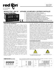
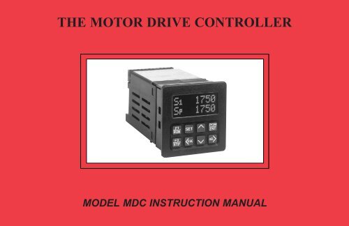
THE MOTOR DRIVE CONTROLLER<br />
MODEL <strong>MDC</strong> INSTRUCTION MANUAL
INTRODUCTION<br />
The Motor Drive Controller (<strong>MDC</strong>) is another unit in our multi-purpose series<br />
of industrial control products that is field-programmable for solving various<br />
applications. This series of products is built around the concept that the end user<br />
has the capability to program different indication and control requirements.<br />
The Motor Drive Controller which you have purchased, has the same high<br />
quality workmanship and advanced technological capabilities that have made<br />
<strong>Red</strong> <strong>Lion</strong> <strong>Controls</strong> the leader in today’s industrial market.<br />
<strong>Red</strong> <strong>Lion</strong> <strong>Controls</strong> has a complete line of industrial indication and control<br />
equipment, and we look forward to serving you now and in the future.<br />
CAUTION: Read complete instructions prior<br />
to installation and operation of the unit.<br />
CAUTION: Risk of electric shock.
TABLE OF CONTENTS<br />
I. GENERAL DESCRIPTION ...........................................................................................4-11<br />
A) Safety Summary .......................................................................................................4<br />
B) Quick Start - Setting Up The <strong>MDC</strong> .......................................................................................5<br />
C) Block Diagram ........................................................................................................6<br />
D) Theory of Operation ...................................................................................................7<br />
E) Normal Operating Mode ................................................................................................8<br />
F) Keypad Description ....................................................................................................9<br />
1. Keypad Functions ...................................................................................................9<br />
G) Dedicated Control Inputs ...............................................................................................10<br />
H) Front Panel Accessible Programming ....................................................................................10<br />
I) Overflow .............................................................................................................11<br />
II. PROGRAMMING GENERAL DESCRIPTION ..........................................................................12<br />
III. USER SETPOINTS MODULE ........................................................................................13-15<br />
A) User Setpoints In Master Mode ..........................................................................................14<br />
1. Speed Setpoint 1 ....................................................................................................14<br />
2. Speed Setpoint 2 ....................................................................................................14<br />
3. Ramp Rate 1 .......................................................................................................14<br />
4. Ramp Rate 2 .......................................................................................................14<br />
5. Jog Speed Setpoint ..................................................................................................14<br />
6. Jog Ramp Rate .....................................................................................................14<br />
7. Alarm 1 Setpoint ...................................................................................................14<br />
8. Alarm 2 Setpoint ...................................................................................................14<br />
9. Error Gain Setpoint .................................................................................................15<br />
B) User Setpoints in Follower Mode. ........................................................................................15<br />
1. Ratio Setpoint 1 ....................................................................................................15<br />
2. Ratio Setpoint 2 ....................................................................................................15<br />
3. Ramp Rate 1 .......................................................................................................15<br />
4. Ramp Rate 2 .......................................................................................................15<br />
IV PROGRAMMING MODULE .........................................................................................16-30<br />
A) Operating Mode Selection Menu ........................................................................................16<br />
B) Program Scaling Menu ...............................................................................................17-18<br />
1. Pulses per Revolution- Feedback ......................................................................................17<br />
2. Maximum RPM- Feedback ...........................................................................................17<br />
3. Display Decimal Point ...............................................................................................17<br />
4. Display Units ......................................................................................................17<br />
5. Pulses per Revolution- Lead ..........................................................................................18<br />
6. Maximum RPM- Lead ...............................................................................................18<br />
-1-
TABLE OF CONTENTS (Cont’d)<br />
IV. PROGRAMMING MODULE (Cont’d) .................................................................................16-30<br />
C) Program User Menu ..................................................................................................19-21<br />
1. No Mode ..........................................................................................................20<br />
2. View Display .......................................................................................................20<br />
3. Change Display .....................................................................................................20<br />
4. Reset Alarms .......................................................................................................20<br />
5. Setpoint Select/Toggle ...............................................................................................20<br />
6. Ramp Select/Toggle .................................................................................................20<br />
7. Ramp Override .....................................................................................................20<br />
8. Setpoint Increment ..................................................................................................21<br />
9. Setpoint Decrement. .................................................................................................21<br />
10. Program Disable ....................................................................................................21<br />
11.Run...............................................................................................................21<br />
12. Ramp Stop .........................................................................................................21<br />
13. Fast Stop...........................................................................................................21<br />
14.Jog................................................................................................................21<br />
D) Program Alarms Menu ................................................................................................22-23<br />
1. Alarm Types .......................................................................................................22<br />
a. High ............................................................................................................22<br />
b.Low.............................................................................................................22<br />
c. Deviation ........................................................................................................22<br />
d. Zero Speed.......................................................................................................22<br />
e. Disabled .........................................................................................................22<br />
2. Phase (+ or -) .......................................................................................................23<br />
3. Boundary or Latched. ................................................................................................23<br />
4. Normal or Fast Update Time ..........................................................................................23<br />
5. Stop Enabled or Disabled .............................................................................................23<br />
E) Program Displays Menu ...............................................................................................24-25<br />
1. Displays 1 to 4. .....................................................................................................24<br />
2. Scroll Speed ........................................................................................................24<br />
F) Program Options Menu. ...............................................................................................26-28<br />
1. Operator Access ....................................................................................................26<br />
2. Feedback Loss Detection .............................................................................................26<br />
3. User Settings .......................................................................................................27<br />
4. <strong>MDC</strong> Factory Settings ...............................................................................................27<br />
5. <strong>MDC</strong> User Setting Chart .............................................................................................28<br />
-2-
TABLE OF CONTENTS (Cont’d)<br />
IV. PROGRAMMING MODULE (Cont’d) .................................................................................16-30<br />
G) Program Diagnostics Menu ............................................................................................29-30<br />
1. Test Inputs .........................................................................................................29<br />
2. Test Alarms ........................................................................................................30<br />
3. Test Drive Output ...................................................................................................30<br />
H) Program Security Menu ................................................................................................30<br />
1. Select Security Code. ................................................................................................30<br />
VII. INSTALLATION & CONNECTIONS .................................................................................31-38<br />
A) Installation Environment. ...............................................................................................32<br />
B) Terminal Connection Drawing ...........................................................................................33<br />
C) Wiring Connections. ...................................................................................................33<br />
1. AC Power Wiring ...................................................................................................33<br />
2. DC Output Power Wiring .............................................................................................34<br />
D) Signal Wiring .......................................................................................................34-36<br />
1. Lead & Feedback Frequency Inputs ....................................................................................34<br />
2. Dedicated Function and User Inputs ....................................................................................35<br />
3. Alarm Outputs 1 and 2 ...............................................................................................35<br />
4. Drive Enable Output .................................................................................................35<br />
5. Isolated Drive Output ................................................................................................36<br />
E) DIP Switch Set-up .....................................................................................................36<br />
VIII. ISOLATED DRIVE OUTPUT CALIBRATION ..........................................................................39<br />
A) Drive Output Span Calibration. ..........................................................................................39<br />
B) Motor Drive Setup .....................................................................................................39<br />
C) Verify System Operation ...............................................................................................39<br />
D) Trim ................................................................................................................39<br />
IX. SPECIFICATIONS & DIMENSIONS .................................................................................40-41<br />
X. TROUBLESHOOTING. ..............................................................................................42-44<br />
XI. APPENDIX “A” - APPLICATIONS ...................................................................................45-46<br />
A) MASTER MODE APPLICATION .......................................................................................45<br />
B) FOLLOWER MODE APPLICATION. ....................................................................................46<br />
XII. APPENDIX “B” - ORDERING INFORMATION .........................................................................47<br />
XIII. APPENDIX “C” - FLOWCHART FOLD-OUT (Insert). ...................................................................�<br />
-3-
GENERAL DESCRIPTION<br />
The Motor Drive Controller (<strong>MDC</strong>) accurately regulates motor speed by<br />
varying an isolated DC control signal to a motor drive system. There are two<br />
modes of operation, Master and Follower.<br />
Master Mode provides control of a motor directly via programmed speed<br />
setpoints in the <strong>MDC</strong>. Regulation is maintained by means of a feedback<br />
frequency to the <strong>MDC</strong> taken from the motor shaft or a downstream shaft pulse<br />
encoder. Follower Mode controls a motor’s speed as a ratio to a second<br />
motor’s speed or outside frequency source. The <strong>MDC</strong> is a “speed” follower. It<br />
does not track the lead motor’s position. Ratio setpoints are programmed into<br />
the unit causing the motor to “follow” the lead motor’s speed at a fixed ratio.<br />
The <strong>MDC</strong> has two programmable speed setpoints and two ramp setpoints<br />
in master mode. Follower Mode has two ratio setpoints and two ramp<br />
setpoints. Both modes share a jog speed setpoint and a jog ramp setpoint. All<br />
setpoints are retained in non-volatile memory when the unit is powered down.<br />
There are five dedicated control inputs on the <strong>MDC</strong>:<br />
RUN<br />
RAMP STOP<br />
FAST STOP<br />
JOG<br />
OPEN LOOP<br />
There are six programmable control inputs: two front panel function keys<br />
and four remote User Inputs. The F1 and F2 keys are factory programmed for<br />
RUN and R-STOP respectively. This eliminates the need for external<br />
switches in some applications.<br />
There are three solid state outputs, two are programmable and one is a<br />
dedicated DRIVE ENABLE output. Programmable functions include:<br />
HIGH ALARM<br />
LOW ALARM<br />
DEVIATION ALARM<br />
ZERO SPEED<br />
DISABLED<br />
Outputs may be programmed for boundary or latching operation, and high<br />
or low acting. There are also two programmable alarm update rates, Normal<br />
and Fast.<br />
-4-<br />
Application flexibility is provided through the two-line by eight-character<br />
alphanumeric display. The display features English language menus for easy<br />
viewing and simplified programming. The four scroll-through Indication<br />
Displays can be programmed to show various parameters and to<br />
automatically scroll, if desired. A program disable DIP switch used with an<br />
external User Input can be utilized to protect the settings and guarantee that<br />
no unwanted changes occur during operation.<br />
Changing speed setpoints and programming information is easily<br />
accomplished by scrolling through menus and selecting the correct<br />
parameter. There are three main Modules:<br />
INDICATION DISPLAY MODULE<br />
USER SETPOINTS MODULE<br />
PROGRAMMING MODULE<br />
Scaling is accomplished by entering the number of feedback pulses per<br />
revolution (PPR), the maximum RPM, and the maximum display units. The<br />
<strong>MDC</strong> is factory configured for an isolated 0 to 10 VDC drive output signal.<br />
The drive output signal can be adjusted to span from 0 to a maximum of 5<br />
through 15 VDC via an accessible potentiometer. The drive output is jumper<br />
selectable for an external reference voltage. To use the external reference, the<br />
<strong>MDC</strong> is connected to the drive in place of an external speed potentiometer.<br />
The construction of the <strong>MDC</strong> unit is a lightweight, high impact plastic case<br />
with a clear viewing window. The sealed front panel with the silicone rubber<br />
keypad meets NEMA 4X/IP65 specifications for wash-down and/or dusty<br />
environments, when properly installed. Plug-in style terminal blocks<br />
simplify installation and wiring change-outs.<br />
SAFETY SUMMARY<br />
All safety related regulations, local codes and instructions that appear in<br />
the manual or on equipment must be observed to ensure personal safety and to<br />
prevent damage to either the instrument or equipment connected to it. If<br />
equipment is used in a manner not specified by the manufacturer, the<br />
protection provided by the equipment may be impaired.<br />
Do not use this unit to directly command motors, valves, or other actuators<br />
not equipped with safeguards. To do so, can be potentially harmful to persons<br />
or equipment in the event of a fault to the unit.
QUICK START - SETTING UP THE <strong>MDC</strong><br />
While it is generally recommended that you read this instruction manual<br />
thoroughly before attempting to set up and operate the model <strong>MDC</strong> Motor<br />
Drive Controller, the following quick set-up procedure provides the basic<br />
steps to get the <strong>MDC</strong> up and running.<br />
1. Read “General Description” and “Block Diagram” to familiarize yourself<br />
with the Basic Connections. (A/C, Inputs, Outputs, etc).<br />
2. Wire or set the Control Inputs to their proper states:<br />
- RUN may be left open for front panel control, or wired to common<br />
through a momentary, normally OPEN switch for remote<br />
operation.<br />
- R-STOP may be tied to common for front panel control, or wired to<br />
common through a momentary, normally CLOSED switch for<br />
remote operation.<br />
- F-STOP must be tied to common or wired to common through a<br />
momentary, normally CLOSED switch.<br />
- JOG must be left open or wired to a momentary, normally OPEN switch<br />
requiring a sustained closure for Jog mode.<br />
- OPEN LOOP must be left open for normal closed loop control, or wired<br />
to a switch which can be maintained in the open or closed position,<br />
depending on User preference.<br />
Refer to “Dedicated Control Function and User Inputs” in the “Installation<br />
and Connections” section for more information.<br />
3. Set the AC power selection switch and connect AC to the <strong>MDC</strong> as noted in<br />
“AC Power Wiring” in the “Installation and Connections” section.<br />
4. Review “Programming General Description” and “Keypad Description” to<br />
familiarize yourself with the Front Panel Programming procedure.<br />
5. To set up the <strong>MDC</strong> for Master Mode - Program the scaling variables for<br />
PPR FB, MAX RPM FB, DSP DP, and DSP UNIT. Refer to the “Program<br />
Scaling Menu”.<br />
6. To set up the <strong>MDC</strong> for Follower Mode - Select Follower Mode in the<br />
Operating Mode Selection Menu. Program the scaling variables for PPR<br />
FB, MAX RPM FB, DSP DP, and DSP UNIT. Refer to “Program Scaling<br />
Menu”. Pay particular attention to “Additional Scale Factors in Follower<br />
Mode”. This will explain the two additional required variables PPR LD and<br />
-5-<br />
RPM LD, which are part of setting the Unity Ratio. Understanding the<br />
Unity Ratio is crucial to scaling in Follower Mode.<br />
7. Refer to “Isolated Drive Output Calibration” section to determine if the<br />
<strong>MDC</strong> Drive Output span needs to be calibrated. Most applications require<br />
calibration of the drive only. Calibrate the drive as noted in “Motor Drive<br />
Setup”.<br />
8. Disconnect AC power. Wire the <strong>MDC</strong> to the motor drive. Refer to “Wiring<br />
from <strong>MDC</strong> to Motor Drive” in the “Installation and Connections” section.<br />
9. Wire the FEEDBACK and LEAD (follower mode only) frequency inputs.<br />
Set the DIP Switches as required. Refer to the “Installation and<br />
Connections” section.<br />
10. Apply power to the <strong>MDC</strong> and Drive.<br />
11. To run the motor, connect the RUN Input to common momentarily or<br />
press the F1\RUN key, located on the Front Panel. The <strong>MDC</strong> will run the<br />
motor to the selected setpoint using the currently selected ramp rate. If the<br />
setpoint is changed during Run Mode using the Front Panel Keypad or a<br />
remote input, the <strong>MDC</strong> will either accelerate or decelerate the motor to the<br />
new setpoint using the current ramp rate.<br />
12. To stop the motor, momentarily disconnect the R-Stop Input from<br />
common or press the “F2/STP” key, located on the Front Panel. The <strong>MDC</strong><br />
will decelerate the motor using the currently selected ramp rate.<br />
13. Disconnecting F-Stop momentarily from common will cause the <strong>MDC</strong> to<br />
take the Drive Output voltage immediately to zero volts. This will cause<br />
the motor to execute a Fast Stop uncontrolled by the ramp rate. If the<br />
F-Stop Input remains open from common, the Run and Jog inputs are<br />
disabled and the Drive Output voltage is fixed at zero volts. A maintained<br />
switch should be used on the F-Stop input if this type of lock out is desired.
BLOCK DIAGRAM<br />
-6-
THEORY OF OPERATION<br />
In Master Mode, the <strong>MDC</strong> uses actual motor speed (Feedback Input) and an<br />
analog control voltage (Drive Output) to precisely control the motor’s speed.<br />
The <strong>MDC</strong> operates on a 10 msec control cycle. Actual motor speed is read and<br />
drive output is corrected every 10 msec. The Drive Output voltage is<br />
generated by a 12 bit DAC (digital to analog converter). Motor speed is<br />
controlled by adjusting the Output Value (in bits) to the DAC.<br />
The Output Value (0 to 4095 bits) is made up of two parts, the Open Loop<br />
term, and the correction term or Trim Value. The Open Loop term is the ratio<br />
of the Reference Speed to Maximum Speed multiplied by 4095. This is the<br />
uncorrected “Feed Forward” part of the Output Value. The Reference Speed<br />
is the current Speed setpoint taking into account any acceleration or<br />
deceleration which may be in progress. The Maximum Speed is Max RPM<br />
Feedback which is set when scaling the unit. (See the Program Scaling section<br />
of the manual for more information.)<br />
The correction term or Trim Value is derived from actual motor speed<br />
(Feedback Input) and the Reference Speed. The Trim Value is added to the<br />
Open Loop term when the <strong>MDC</strong> is running Closed Loop to provide precise<br />
control. The Error Gain determines the rate at which the Trim Value changes<br />
in response to a motor loading or a sudden speed change. The Trim Value is<br />
updated every 10 msec. It may be viewed as one of the programmable display<br />
options (see Program Displays Menu).<br />
The Drive Output voltage is then the ratio of Output Value (in bits) to 4095<br />
multiplied by the Full Scale Reference voltage. The internal Full Scale<br />
Reference is factory calibrated to 10 VDC but may be adjusted to any value<br />
within a5to15VDCrange. An external reference option also exists. (See<br />
Isolated Drive Output section of manual for more information.)<br />
In Follower Mode, the basic operation is the same except that the<br />
Reference Speed is generated as a ratio to the Lead Input speed. Also, the<br />
<strong>MDC</strong> operates on a 20 msec control cycle in order to process both Lead and<br />
Feedback input frequencies.<br />
-7-
NORMAL OPERATING MODE<br />
When the <strong>MDC</strong> is powered up, it is in the Normal Operating<br />
Mode with the Indication Display Module viewed. The up and<br />
down arrow keys are used to scroll through the Indication<br />
Displays. The Indication Displays are referenced as 1 to 4 with<br />
the factory default settings of 1 (SPEED), 2 (OPERATING<br />
STATUS), 3 (ALARM STATUS), and 4 (TRIM). The Indication<br />
Displays can be programmed to show other parameters and<br />
automatically scroll if desired (See Program Displays Menu for<br />
details). All Dedicated Function Inputs, User Inputs, and Alarm<br />
Outputs are operational in the Normal Operating Mode.<br />
From the Normal Operating Mode, two other modules may be<br />
entered. The SET key enters the User Setpoints Module and the<br />
PGM key enters the Programming Module. The last display<br />
viewed when exiting the Indication Display Module will be the<br />
first display viewed upon return. Also, the last Indication Display<br />
viewed at power down, will be the one viewed on power up.<br />
The User Setpoints Module may be accessed from any of the<br />
Indication Displays or from the Programming Module (with the<br />
exception of the Operating Mode Selection Menu). The<br />
Setpoints Module is used to set all of the user setpoints, such as<br />
speed, alarm, and gain values (see Programming User<br />
Setpoints). User Setpoints may be edited while the <strong>MDC</strong> is in a<br />
RUN or JOG mode.<br />
The flowchart at right shows the three main Modules that are<br />
accessible in the Normal Operating Mode.<br />
-8-
KEYPAD DESCRIPTION<br />
Shown here is a diagram of the keypad and a<br />
description of each key. Some keys have a dual<br />
function.<br />
F1<br />
RUN<br />
F2<br />
STP<br />
SET<br />
<br />
KEYPAD FUNCTIONS (Cont’d)<br />
- The Down arrow key scrolls through the Indication Displays. When<br />
in the User Setpoints Module, it is used to decrement the current<br />
speed setpoint (Setpoint Scroll Menu), or to scroll through the<br />
setpoint values. In the Programming Module, it scrolls through the<br />
programming menus and sub menus. When programming a<br />
numerical value, it decrements the selected digit.<br />
- The Program/Enter key displays “Program Mode” when pressed in<br />
the Indication Display Module and initiates entry into the<br />
Programming Module. This key is also used to store a new value<br />
when a selection is made in an edit menu.<br />
- The Select/Right arrow key selects the digit to the right when<br />
programming a numerical value. It is also used to enter the<br />
Programming Module from the “Program Mode” display. In a<br />
sub-menu loop, it is used to go to the next lower level and eventually<br />
into an edit menu.
DEDICATED CONTROL INPUT FUNCTIONS<br />
The Motor Drive has inputs dedicated to certain primary operations. These<br />
functions are as follows:<br />
RUN<br />
A momentary closure to common on the RUN input causes the <strong>MDC</strong> to<br />
accelerate the motor from STOP mode to the current speed setpoint using the<br />
current ramp rate.<br />
R-STOP<br />
A momentary open from common on the R-STOP input causes the <strong>MDC</strong> to<br />
decelerate the motor from its current speed to STOP mode using the current<br />
ramp rate.<br />
F-STOP<br />
A momentary open from common on the F-STOP input causes the <strong>MDC</strong> to<br />
execute a fast stop, taking the analog Drive Output signal immediately to zero<br />
volts. Motor deceleration is limited only by the motor drive system. This is an<br />
emergency stop function. The Drive Enable Output goes immediately to its<br />
inactive state and may be used to engage braking or remove power from the<br />
motor via an external relay.<br />
JOG<br />
The jog function only operates from the STOP mode. A sustained closure<br />
from the JOG input to common causes the <strong>MDC</strong> to accelerate the motor to the<br />
jog speed setpoint using the jog ramp rate. The motor remains at the jog speed<br />
until the closure is removed, at which point the <strong>MDC</strong> executes an F-STOP.<br />
OPEN LOOP<br />
A maintained closure to common on this input causes the <strong>MDC</strong> to run open<br />
loop. The error correction value, Trim, is set to zero and speed is not<br />
regulated. A momentary closure on this input can be used as a Trim reset, to<br />
momentarily reset the Trim value to zero.<br />
Note: Feedback Loss Detection is automatically disabled in Open Loop Mode.<br />
-10-<br />
FRONT PANEL ACCESSIBLE PROGRAMMING<br />
The <strong>MDC</strong> has several ways to limit the programming of parameters in the<br />
User Setpoints Module and the Programming Module. The Operator Access<br />
Menu, in the Programming Module, can be used with the Program Disable<br />
(PGM. DIS) DIP switch or an external User Input to limit programming of<br />
parameters in the User Setpoints Module.<br />
To enter the Programming Module, a program code number may need to be<br />
entered, depending on the Program Disable Function setting. Only external<br />
User Inputs can be selected for program disable. The default value for the<br />
program code number is “00”, but should be programmed differently (See<br />
Program Security Menu). This helps prevent inadvertent entry into the unit’s<br />
programming modules. When PROGRAM MODE is displayed and then the<br />
SEL key is pressed, the PRO.CODE prompt will be viewed. At this time, the<br />
Code number must be entered using the arrow keys. After selecting the proper<br />
code number and pressing the Enter key, the operator advances into the<br />
Programming Module. If the wrong code number is entered, the operator will<br />
not be able to enter the Programming Module and the unit returns to the<br />
PROGRAM MODE display. The following list describes the possible<br />
program disabling functions.<br />
PGM.DIS<br />
SWITCH<br />
USER INPUT<br />
TERMINAL<br />
OFF INACTIVE or Not<br />
Programmed for<br />
PGM.DIS<br />
PROGRAM<br />
CODE<br />
ACTION<br />
NUMBER<br />
N/A Complete programming enabled.<br />
OFF ACTIVE 0 to 98 Operator Accessible Functions,<br />
Programming Loop Accessible via<br />
Code number.<br />
OFF ACTIVE 99 Operator Accessible Functions,<br />
Programming Loop Disabled.<br />
ON INACTIVE or Not<br />
Programmed for<br />
PGM.DIS<br />
ON INACTIVE or Not<br />
Programmed for<br />
PGM.DIS<br />
0to98<br />
99<br />
Operator Accessible Functions,<br />
Programming Loop Accessible via<br />
Code number.<br />
Operator Accessible Functions,<br />
Programming Loop Disabled.<br />
ON ACTIVE N/A No Accessible Functions,<br />
Programming Disabled.
OVERFLOW INDICATION<br />
An input frequency overflow occurs in the normal operating mode when<br />
the input frequency specifications are exceeded. The <strong>MDC</strong> continuously<br />
displays “FB FREQ OVERFLOW”, or “LD FREQ OVERFLOW” when the<br />
respective input frequency exceeds specifications.<br />
A second type of overflow is an Indication Display overflow. The <strong>MDC</strong><br />
flashes the word “OVERFLOW” in the appropriate display when the<br />
overflow condition occurs. A display overflow occurs if the capacity of the<br />
display is exceeded. This can occur when DSP UNIT (Maximum Display<br />
Units) is scaled near the limit and the motor speed exceeds the scale value<br />
MAX RPM FB (Maximum Feedback RPM). For example, if DSP UNIT is<br />
set to 99999 and MAX RPM FB is set to 1750, the SPEED display overflows<br />
if the motor exceeds 1750 RPM.<br />
A third type of overflow occurs in the Program Scaling Menu. If a PPR<br />
(Pulses per Revolution) or MAX RPM value is entered which causes the<br />
Maximum Equivalent Frequency (FB or LD) to exceed 20971 Hz, a Scaling<br />
overflow occurs. The display flashes “OVFLW” in place of the numeric<br />
value and a new value is required. The equivalent frequency can be<br />
determined by:<br />
Maximum Equivalent Frequency =<br />
PPR x MAX RPM<br />
60<br />
-11-
PROGRAMMING GENERAL DESCRIPTION<br />
Programming is done through the front panel keypad, which allows the<br />
user to enter into Main Menus, Sub-Menus, and Edit Menus. English<br />
language prompts, flashing parameter values, and the front panel keypad aid<br />
the operator during programming.<br />
Although the unit has been programmed at the factory, the parameters<br />
generally have to be changed to suit the desired application. From the<br />
Indication Display Module, the Programming Module is entered by pressing<br />
the Program/Enter (PGM/ENT) key. This displays “PROGRAM MODE”.<br />
Then press the Select (SEL) key to enter the Programming Module. The Up<br />
and Down arrows are used to scroll through the main menus. Pressing Select<br />
(SEL) from a main menu, allows the user to enter a Sub-Menu where<br />
parameter values can be viewed. Parameter values are changed and entered<br />
in the Edit Menu. There are two types of Edit Menus:<br />
1. A Choice Edit Menu allows the operator to scroll through options by<br />
pressing the down arrow key until the desired option is viewed. The option<br />
is entered by pressing the PGM/ENT (enter) key, which returns the<br />
operator to the previous sub-menu. The operator can exit the Edit Menu<br />
WITHOUT making a selection by pressing the
USER SETPOINTS MODULE<br />
The User Setpoints Module is accessed<br />
from any of the Indication Displays, or<br />
from any of the main menus in the<br />
Programming Module (except Operating<br />
Mode Menu), by pressing the SET key.<br />
Pressing “SET” once enters the<br />
Setpoint Scroll Menu. In this menu, the<br />
current speed or ratio setpoint may be<br />
incremented or decremented using the Up<br />
and Down arrow keys. The top line of the<br />
display shows the current setpoint value<br />
and the bottom line shows actual speed in<br />
display units.<br />
Pressing “SET” a second time enters the<br />
User Setpoints Menu. The top line shows<br />
the Setpoint description and the bottom<br />
line shows the Setpoint value. The up and<br />
down arrow keys may be used to scroll<br />
through the loop. Pressing the SEL key<br />
allows the value to be changed in a Value<br />
Edit Menu. Press ESC to exit the User<br />
Setpoints Module.<br />
The following flowchart shows only the<br />
User Setpoints portion:<br />
� Note: These maximums are<br />
additionally limited by unit<br />
scaling. See individual<br />
descriptions for details.<br />
-13-
USER SETPOINTS IN MASTER MODE<br />
Speed Setpoint 1 (S1)<br />
Speed Setpoint 1 is one of two user selectable speeds used in “RUN” mode.<br />
The speed value is entered in display units (user units) as defined in the<br />
Program Scaling Menu. The value ranges from 0 to 99999, provided the<br />
Display Unit Maximum set in Program Scaling is 99999. Otherwise, the speed<br />
value is limited to the Display Unit Maximum. If a value greater than or equal to<br />
the Display Unit Maximum is entered, the message “MAX RPM LIMIT”<br />
flashes on the display and the maximum speed is automatically entered.<br />
Speed Setpoint 2 (S2)<br />
Speed Setpoint 2 is the second user selectable speed used in “RUN” mode.<br />
A User Input must be configured to allow selection of Setpoint 1 or 2 for use<br />
as the current speed setpoint. If no User Input is configured for setpoint<br />
selection (SPT SEL), the factory default setting is Speed Setpoint 1 (see<br />
Program User Menu for details).<br />
Ramp Rate 1 (RAMP 1)<br />
Ramp Rate 1 is used for acceleration and deceleration between “RUN” and<br />
“STOP” modes or between speed setpoints. The ramp rate value is entered in<br />
display units/second. For example, if the Display Units are RPM, then the<br />
ramp rate is RPM/SEC. The value ranges from 1 to 99999, provided that it is<br />
not greater than or equal to the internal limit of 20,000 feedback pulses per<br />
second. If this occurs, the message “MAX RAMP RATE” flashes on the<br />
display and the maximum ramp rate is automatically entered. A “0” value<br />
may be entered, which automatically selects the maximum ramp rate.<br />
Ramp Rate 2 (RAMP 2)<br />
Ramp Rate 2 is the second user selectable ramp rate. A User Input must be<br />
configured to allow selection of RAMP 1 or 2 for use as the current ramp rate.<br />
If no User Input is configured for ramp selection (RAMP SEL), the factory<br />
default setting is RAMP 1 (see Program User Menu for details).<br />
-14-<br />
Jog Speed (JOG SPD)<br />
The Jog Speed setpoint is used in JOG mode (See JOG under Dedicated<br />
Control Input Functions for details). The value entered is in display units with<br />
the same range and limitations as Speed Setpoint 1.<br />
Jog Ramp Rate (JOG RAMP)<br />
The Jog Ramp Rate applies when entering JOG mode and accelerating to<br />
the Jog Speed. The value entered is in display units/sec. with the same range<br />
and limitations as Ramp Rate 1.<br />
Alarm 1 (AL-1)<br />
The Alarm 1 value is entered in display units. This value affects the Alarm<br />
1 output. The alarm type is programmable and may be: High Speed, Low<br />
Speed, Deviation, or Zero Speed. A Zero Speed alarm has no Value Edit<br />
Menu. The value range for an alarm setpoint may be 0 to 99999, provided that<br />
it is not greater than the internal equivalent of 20971 feedback pulses per<br />
second. If this occurs, the message “SCALING LIMIT” is flashed on the<br />
display and the maximum value is automatically entered.<br />
Alarm 2 (AL-2)<br />
The Alarm 2 value affects the Alarm 2 output. It is programmable and has<br />
the same range and limitations as Alarm 1.<br />
Error Gain (GAIN)<br />
The Error Gain affects the closed loop response to a deviation from the<br />
speed setpoint. It has a value range of 0 to 99. A “0” entry eliminates<br />
correction for speed error. A “99” entry provides maximum correction for<br />
speed error and is the factory default setting. If instability or oscillation in<br />
motor speed occurs, this value should be reduced.
USER SETPOINTS IN FOLLOWER MODE<br />
The setpoints listed below are independent FOLLOWER mode setpoints.<br />
They are retained separately from the MASTER mode setpoints in<br />
non-volatile memory. Jog, Alarm, and Gain values are shared parameters<br />
used by both MASTER and FOLLOWER modes.<br />
Ratio Setpoint 1 (S1)<br />
Ratio Setpoint 1 is one of two user selectable ratio setpoints used in “RUN”<br />
mode. The ratio value entered sets the follower motor’s speed as a ratio to the<br />
lead signal input. The range is 0.0000 to 1.9999.<br />
Follower Speed (RPM) = Ratio Setpoint x Unity Ratio x Lead Speed (RPM)<br />
A ratio setpoint of 1.0000 implies that the follower motor will run at the<br />
same speed as the lead motor if the Unity Ratio is 1.0. The unity ratio is<br />
determined by the values entered for MAX RPM FB and MAX RPM LD in the<br />
Program Scaling Menu.<br />
Ratio Setpoint 2 (S2)<br />
Ratio Setpoint 2 is the second user selectable Ratio setpoint. A User Input<br />
must be configured to allow selection of Setpoint 1 or 2 for use as the current<br />
Ratio setpoint. If no User Input is configured for setpoint selection (SPT<br />
SEL), the factory default setting is Setpoint 1. (See Program User Menu).<br />
Ramp Rate 1 (RAMP 1)<br />
Ramp Rate 1 is one of two user selectable ramp rates used for acceleration<br />
and deceleration between “RUN” and “STOP” modes or between ratio<br />
setpoints. The ramp rate value is entered in ratio units/second. The value<br />
ranges from 0.0001 to 1.9999 ratio units/sec. A value of 0.0000 may be<br />
entered to select the maximum ramp rate of 1.9999. This causes the message<br />
“MAX RAMP RATE” to be flashed on the display and the maximum ramp<br />
rate of 1.9999 to be automatically entered.<br />
-15-<br />
Ramp Rate 2 (RAMP 2)<br />
Ramp Rate 2 is the second user selectable ramp rate. A User Input must be<br />
configured to allow selection of RAMP 1 or 2 for use as the current ramp rate.<br />
If no User Input is configured for ramp selection (RAMP SEL), the factory<br />
default setting is RAMP 1 (see Program User Menu).
PROGRAMMING MODULE<br />
The Programming Module is used to access all parameters for configuring<br />
the unit. To enter the Programming Module, the user must first press<br />
PGM/ENT from the Indication Display Module. This causes “PROGRAM<br />
MODE” to be displayed. The user must then press SEL to enter the<br />
Programming Module. Depending upon the program disable state, access to<br />
the Programming Module may be denied or require a security code entry. (See<br />
Front Panel Accessible Programming.) The <strong>MDC</strong> will ramp to the STOP<br />
mode if you enter the Programming Module while the unit is in the RUN<br />
mode. The Display will flash “RAMPING DOWN” when the SEL key is<br />
pressed. The <strong>MDC</strong> must be in STOP mode before any programming changes<br />
can be made. While the unit is ramping down, F-STOP may be used to enter<br />
STOP mode immediately. The operation of the Dedicated Control Inputs and<br />
Alarm outputs is disabled while in the Programming Module, except as noted<br />
in the Program Diagnostics Menu.<br />
-16-<br />
OPERATING MODE SELECTION MENU<br />
The Operating Mode Selection Menu indicates the <strong>MDC</strong>’s current<br />
operational mode. The factory default setting is MASTER mode.<br />
FOLLOWER mode may be selected by pressing SEL, DN arrow, and ENT. It<br />
is important to select the operational mode prior to scaling the <strong>MDC</strong> and<br />
entering User Setpoints. Setpoints S1, S2, Ramp 1, and Ramp 2 are speed<br />
units in MASTER mode and ratio units in FOLLOWER mode.<br />
The following flowchart shows Operating Mode Selection only:
PROGRAM SCALING MENU<br />
The Program Scaling Menu is used to scale the <strong>MDC</strong> to the specific motor<br />
(or shaft) feedback transducer output. This Menu also scales the speed in<br />
RPM to the Display units which are seen on the display and used for speed<br />
setpoint entry.<br />
The following flowchart shows only the Scaling portion:<br />
-17-<br />
PPR FB (Pulses Per Revolution- Feedback)<br />
Enter the number of pulses per revolution generated by the feedback<br />
transducer. The value for PPR FB ranges from 1 to 59999.<br />
MAX RPM FB (Maximum RPM- Feedback)<br />
Enter the maximum RPM for the feedback input transducer. This is the<br />
maximum normal operating speed (in RPM) of the motor (or shaft) which is<br />
generating the feedback signal. The value ranges from 1 to 59999.<br />
Note: If the Maximum Equivalent Frequency exceeds 20971 Hz, “OVFLW”<br />
flashes over the numeric value and a new entry is required.<br />
Maximum Equivalent Frequency =<br />
PPR x MAX RPM<br />
60<br />
DSP DP (Display Decimal Point)<br />
Select the display decimal point position. Press SEL and use the DN arrow<br />
key to select the decimal point position. The decimal point position is a place<br />
holder only and does not affect scaling. The available options are:<br />
0<br />
0.0<br />
0.00<br />
0.000<br />
0.0000<br />
0.00000<br />
DSP UNIT (Maximum Display Units)<br />
Enter the value to be displayed when the motor (or shaft) is running at the<br />
speed entered for MAX RPM FB. This value is also the maximum allowable<br />
speed setpoint. The value ranges from 1 to 99999.
PROGRAM SCALING MENU (Cont’d)<br />
ADDITIONAL SCALE FACTORS IN FOLLOWER MODE<br />
PPR LD (Pulses Per Revolution- Lead)<br />
Enter the number of pulses per revolution generated by the lead transducer.<br />
If an artificial frequency source is used, set PPR LD to 60. This SETS 1 RPM<br />
= 1 Hz. Max RPM Lead can then be entered in Hz. The value for PPR LD<br />
ranges from 1 to 59999.<br />
MAX RPM LD (Maximum RPM- Lead)<br />
This variable sets the unity ratio. Enter the desired RPM for the lead input<br />
transducer which would cause the follower motor (or shaft) to operate at<br />
MAX RPM FB when a ratio setpoint of 1.0000 is entered. The value for Max<br />
RPM LD does not need to be an actual operating maximum for the lead motor.<br />
It only sets the Unity Ratio.<br />
Follower Speed (RPM) = Ratio Setpoint x Unity Ratio x Lead Speed (RPM)<br />
Where: Unity Ratio = MAX RPM FB<br />
MAX RPM LD<br />
This allows the user to define a 1:1 setpoint ratio which is different than the<br />
1:1 speed ratio of the motors. The value entered for MAX RPM LD ranges<br />
from 1 to 59999.<br />
Notes:<br />
1. The maximum input frequency for Follower Mode is 12 kHz (lead and<br />
feedback).<br />
2. For optimum performance, choose the Motor Drive System with the highest<br />
frequency signal output as the master or lead system in a Follower Mode<br />
application.<br />
-18-<br />
For example, in a Master/Follower application where two motors are driving<br />
conveyors which are feeding product into a hopper, conveyor A must run 2X<br />
faster than conveyor B to get a product mix of 1:1. The maximum speed for both<br />
motors is 1750 RPM. We will use motor B for the Follower since it runs slower<br />
than motor A. The max RPM feedback is set to 1750 (the max motor speed for<br />
conveyor B). Set the unity ratio so that a ratio setpoint of 1.0000 can be used to<br />
indicate a 1:1 ratio for the product mix, not the speed ratio of the motors. Since<br />
the lead motor (A) must run at a speed 2X the follower motor (B), set the max<br />
RPM Lead at a value 2X the follower motor max (3500 RPM). This will<br />
produce a follower speed 1/2 the lead speed when a 1.0000 ratio setpoint is<br />
selected. The value for max RPM Lead does not have to be an actual operating<br />
speed for the lead motor, this value simply sets the unity ratio.<br />
MAX RPM FB = 1750<br />
MAX RPM LD = 3500<br />
Unity Ratio = MAX RPM FB = 1750 = 0.5<br />
MAX RPM LD 3500<br />
Using a Ratio Setpoint of 1.0000 and a Lead speed of 1750.<br />
Follower speed = Ratio Stpt. x Unity Ratio x Lead speed (RPM)<br />
Follower speed = 1 x 0.5 x 1750<br />
Follower speed = 875<br />
As you can see, the follower speed is half the lead speed when using a 1.0000<br />
Ratio Setpoint. It is a good practice to set the Unity Ratio so a Ratio Setpoint of<br />
1.0000 can be used as the normal operating setpoint. This will allow the operator<br />
to adjust the Ratio Setpoint in user units of product mix, not motor speeds.
PROGRAM USER MENU<br />
There are four external User<br />
Inputs and two front panel<br />
Function keys, which have a<br />
variety of programmable<br />
capabilities. An external User<br />
Input is active when tied to<br />
common. A front panel function<br />
key is active when pressed. The<br />
options for each User input are the<br />
same, except as noted below:<br />
1. The two Function keys<br />
(F1/RUN & F2/STP) have some<br />
additional functions: RUN (F1<br />
only), R-STOP, F-STOP and JOG.<br />
2. The two Function keys DO<br />
NOT have the Program Disable<br />
(PGM.DIS.) option.<br />
The operator can select only<br />
one option for each User Input.<br />
The operator may enter a second<br />
sub-menu for some options before<br />
entering the edit menu. The<br />
following flowchart shows only<br />
the User portion:<br />
Note: Only F1 may be programmed for<br />
RUN. Programming F1 for run<br />
automatically programs F2 for R-STOP.<br />
F2 may then be programmed to F-STOP<br />
or left as R-STOP.<br />
-19-
PROGRAM USER MENU (Cont’d)<br />
NO MODE<br />
If a User Input terminal or a Function key is activated, it will be ignored.<br />
VIEW DISPLAY (VIEW DSn)<br />
In the Indication Display Module, the unit advances to the Indication<br />
Display selected, when the User Input is activated. In the User Setpoints<br />
Module or Programming Module, the unit advances to the selected display<br />
upon exiting that Module. DS1 selects display 1, DS2 display 2, DS3 display<br />
3, and DS4 display 4. If an input is momentary the display is selected, but can<br />
be changed by use of the up or down arrow keys, or another User Input. If an<br />
input is maintained the display cannot be advanced using the UP and DN<br />
arrow keys on the keypad. If more than one User Input is used for this option,<br />
the priority order from highest to lowest is F2, F1, USR INP4, USR INP3,<br />
USR INP2, and USR INP1. The items viewed on the display are determined<br />
by what is selected in the Program Displays Menu.<br />
CHANGE DISPLAY (CHG DSP)<br />
In the Indication Display Module, when a User Input is activated, the<br />
Indication Display advances to the next Indication Display, this is a momentary<br />
action. If the operator is in the User Setpoint Module or the Programming<br />
Module, the unit advances to the next display upon exiting that Module.<br />
RESET ALARM 1 OUTPUT (RST AL-1)<br />
The operator can select to have Alarm Output 1, 2, or � (both) reset. If the<br />
output is active, it resets to its inactive state when the User Input or function<br />
key is activated. This may be a momentary or maintained action. A<br />
momentary action resets the alarm but it becomes active again within 10 msec<br />
if the alarm trigger condition still exists. A maintained action keeps the alarm<br />
reset regardless of the trigger condition.<br />
Note: The Inactive state of an output can be ON or OFF depending on what is<br />
programmed in the Program Alarms Menu.<br />
-20-<br />
SETPOINT SELECT/TOGGLE (SPT SEL/TOG)<br />
ONLY ONE USER INPUT SHOULD BE PROGRAMMED FOR SPT<br />
SEL/TOG. If more than one is programmed, the highest priority input is<br />
recognized and all of the others are ignored. The priority order from highest to<br />
lowest is USR INP4, USR INP3, USR INP2, USR INP1, F1/F2.<br />
Select<br />
The <strong>MDC</strong> uses S1 (setpoint 1) for its factory default speed or ratio setpoint.<br />
If the User Input is made active, the <strong>MDC</strong> ramps to S2 at the current ramp rate.<br />
Making the input inactive causes the unit to ramp to S1. This is a maintained<br />
setpoint select for User Inputs 1 through 4.<br />
Toggle<br />
For F1 or F2, this is a momentary action causing a setpoint toggle between<br />
S1 and S2.<br />
RAMP SELECT/TOGGLE (RAMP SEL/TOG)<br />
ONLY ONE USER INPUT SHOULD BE PROGRAMMED FOR RAMP<br />
SEL/TOG. If more than one is programmed, the highest priority input is<br />
recognized and all of the others are ignored. The priority order from highest to<br />
lowest is USR INP4, USR INP3, USR INP2, USR INP1, F1/F2.<br />
Select<br />
The <strong>MDC</strong> uses R1 (ramp 1) for its factory default ramp rate for both<br />
acceleration and deceleration. If the User Input is made active, the <strong>MDC</strong> uses<br />
R2. Making the input inactive causes the unit to use R1. This is a maintained<br />
ramp select for User inputs 1 through 4.<br />
Toggle<br />
For F1 or F2, this is a momentary action causing a ramp toggle between R1<br />
and R2.<br />
RAMP OVERRIDE (RAMP OVRD)<br />
Making this input active overrides the acceleration/deceleration ramp<br />
routine causing the unit to jump to the ramp endpoint. This may be a setpoint<br />
change or STOP condition. A momentary action overrides the current ramp in<br />
process. A maintained action overrides the current ramp in process and all<br />
future ramps.<br />
Caution: Significant overshoot of the speed setpoint can occur with this feature.
SETPOINT INCREMENT (INC SPT)<br />
Only an external User Input can be used for this option. The currently<br />
active speed or ratio setpoint is incremented when the User Input is made<br />
active. If the input remains active for more than 5 display unit increments, the<br />
scroll rate will progressively increase.<br />
SETPOINT DECREMENT (DEC SPT)<br />
Only an external User Input can be used for this option. The currently<br />
active speed or ratio setpoint is decremented when the User Input is made<br />
active. If the input remains active for more than 5 display unit increments, the<br />
scroll rate will progressively increase.<br />
PROGRAM DISABLE (PGM.DIS.)<br />
Only an external User Input can be used for this option. When used with the<br />
Program Disable DIP switch, this option can limit operator access to<br />
programmable parameters (see Front Panel Accessible Programming With<br />
Program Disable section). The program disable is maintained.<br />
-21-<br />
Additional Options Available For F1 & F2 Keys<br />
RUN<br />
Activation of a function key selected for RUN causes the <strong>MDC</strong> to<br />
accelerate the motor from STOP mode to the current speed setpoint using the<br />
current ramp rate.<br />
RAMP STOP<br />
Activation of a function key selected for R-STOP causes the <strong>MDC</strong> to<br />
decelerate the motor from its current speed to STOP mode using the current<br />
ramp rate.<br />
FAST STOP<br />
Activation of a function key selected for F-STOP causes the <strong>MDC</strong> to<br />
execute a fast stop, taking the analog Drive Output signal immediately to zero<br />
volts. Motor deceleration is limited only by the motor drive system. This is an<br />
emergency stop function. The Drive Enable Output goes immediately to its<br />
inactive state and may be used to engage braking or remove power from the<br />
motor via an external relay.<br />
JOG<br />
The jog function only operates from the STOP mode. Pressing and holding a<br />
function key selected for JOG causes the <strong>MDC</strong> to accelerate the motor to the<br />
jog speed setpoint using the jog ramp rate. The motor remains at the jog speed<br />
until the function key is released, at which point the <strong>MDC</strong> executes an F-STOP.
PROGRAM ALARMS MENU<br />
Alarm parameters 1 and 2 activate solid state Alarm Outputs 1<br />
and 2 respectively. A manual reset, which requires the use of a<br />
User Input, will reset an Alarm Output (see Program User Menu).<br />
Both alarms may be programmed for any of the five alarm<br />
functions: High Alarm, Low Alarm, Deviation Alarm, Zero<br />
Speed Alarm, and Disabled. The following flowchart shows only<br />
the Alarms portion:<br />
ALARM TYPES<br />
High Alarm (HIGH ALM)<br />
The alarm output activates when the feedback input registers a<br />
speed greater than or equal to the alarm value in display units.<br />
Low Alarm (LOW ALM)<br />
The alarm output activates when the feedback input registers<br />
a speed less than or equal to the alarm value in display units. The<br />
alarm may be active or inactive in stop mode (see Stop Enabled<br />
or Disabled).<br />
Deviation Alarm (DEV ALM)<br />
The alarm output activates when the feedback input registers a<br />
speed outside of a � band around the current speed or ratio<br />
setpoint. The band is equal to the � alarm value in display speed<br />
units. The alarm may be active or inactive in stop mode (see Stop<br />
Enabled or Disabled).<br />
For Example: A speed setpoint of 1000, with an alarm setpoint<br />
of 10 would activate the alarm when the speed fell below 990 or<br />
went above 1010.<br />
Zero Speed Alarm (ZERO SPD)<br />
The alarm output activates when the feedback input receives no<br />
input pulse for at least 1 second. There is no alarm value<br />
associated with the Zero Speed Alarm.<br />
Disabled<br />
The alarm output is inactive when disabled.<br />
-22-
Phase<br />
The positive (+) phase of an output indicates that when the alarm becomes<br />
active, the output turns on. When the output is reset it is turned off.<br />
The negative (-) phase of an output indicates that when the alarm becomes<br />
active, the output turns off. The reset condition of the output is the on state.<br />
Boundary or Latched<br />
An alarm programmed for Boundary Output becomes active as determined<br />
by the alarm type (High, Low, Deviation, or Zero Speed). The output stays<br />
active as long as this alarm trigger condition exists, after which the output<br />
returns to its inactive state. A maintained reset on a User Input programmed<br />
for Reset Alarm causes the alarm to stay in its inactive state at all times (see<br />
Program User Menu).<br />
An alarm programmed for Latched Output becomes active as determined<br />
by the alarm type (High, Low, Deviation, or Zero Speed). The output stays<br />
active until it is manually reset by a User Input selected for that function. A<br />
momentary reset causes the output to return to its inactive state provided that<br />
the condition causing the alarm no longer exists. A maintained reset on a User<br />
Input programmed for Reset Alarm causes the alarm to stay in its inactive<br />
state at all times (see Program User Menu).<br />
Normal or Fast Update<br />
The Normal update for the alarm outputs is once each second. This is the<br />
same as the Speed or Ratio display update. The calculation to check for the<br />
alarm condition is made from an average value of feedback measurements<br />
taken over a 1 second period.<br />
The Fast alarm update occurs at an interval less than or equal to 40 msec.<br />
The calculation to check for the alarm condition is made from a single<br />
feedback and/or lead frequency measurement. Since no average is made,<br />
peaks caused by pulse encoder non-linearity (such as differences in the<br />
spacing of teeth on a gear or an unbalanced shaft) can cause the alarm to<br />
trigger early. THE FAST UPDATE SHOULD ONLY BE USED WHEN<br />
FAST RESPONSE IS NECESSARY.<br />
-23-<br />
Stop Enabled or Disabled<br />
This is an option that pertains only to the Low alarm and Deviation alarm. It<br />
refers to the alarm function when the <strong>MDC</strong> is in STOP mode or ramping to or<br />
from STOP mode. When the alarm is Stop Enabled, the alarm functions<br />
normally in stop mode. A low alarm would always be on since zero speed is<br />
always less than or equal to the speed setpoint.<br />
When the alarm is programmed to be Stop Disabled, the alarm is always<br />
inactive in stop mode and when ramping to or from stop mode. The alarm can<br />
only become active after the speed setpoint value has been attained in Master<br />
Mode, or when the ramp up to the setpoint ratio is complete in Follower Mode.
PROGRAM DISPLAYS MENU<br />
Each line of each Indication Display can be programmed individually to<br />
show mnemonics or a numeric value for: Speed/Ratio Setpoint 1 or 2, Speed,<br />
Ratio, % Deviation, % Output, Feedback Frequency, Lead Frequency, Alarm<br />
1 or 2 setpoint and Trim. Or, each line may be programmed to one of the two<br />
status displays: Operating Status or Alarm Output status. If an Indication<br />
Display is to show two different numeric values, one for each line, there will<br />
be a single or dual character mnemonic to the left of the numeric value. This<br />
will also be true if one line is programmed for operating status or alarm output<br />
status. The flowchart on the following page shows only the Display portion:<br />
DISPLAYS 1 TO 4<br />
Each line of each display has the same programmable options. MNE is the<br />
abbreviation for Mnemonics and VAL is for Value. The following list shows<br />
the single or dual character mnemonics that will be displayed when VAL is<br />
selected and the full mnemonic when MNE is selected:<br />
VAL MNE DESCRIPTION<br />
S1 99999 SETPT. 1 Speed or ratio setpoint 1<br />
S2 99999 SETPT. 2 Speed or ratio setpoint 2<br />
Sp 99999 SPEED Actual speed in user display units (feedback)<br />
R 1.999 RATIO Actual feedback to lead input speed ratio<br />
(follower mode)<br />
%D 100.0 % DEV. % deviation of actual speed from target speed<br />
%O 100.0 % OUTPUT Analog drive output- % of full scale voltage<br />
FB 20971 FB. FREQ Feedback frequency in pulses/sec (Hz.)<br />
LD 12000 LD. FREQ Lead frequency in pulses/sec (Hz.)<br />
A1 99999 ALARM 1 Alarm 1 setpoint<br />
A2 99999 ALARM 2 Alarm 2 setpoint<br />
Tr 4095 TRIM Error correction in bits (-4095 to +4095)<br />
(See Isolated Drive Output Calibration section)<br />
-24-<br />
Status displays:<br />
Operating Status<br />
(setpoint 1, ramp rate 1, Run mode)<br />
Alarm Output Status<br />
(alarm 1 inactive, alarm 2 active)<br />
Operating Status<br />
(setpoint 1, ramp rate 1, Stop mode)<br />
Alarm Output Status<br />
(alarm 1 active, alarm 2 inactive)<br />
Operating Status<br />
The operating status display indicates the currently active speed or ratio<br />
setpoint (S1 or S2), the currently active ramp rate (R1 or R2), and the mode of<br />
operation (RUN, STP, or JOG). An arrow will replace the “R” for the currently<br />
active ramp rate indication when an actual ramp up or down is in progress.<br />
Alarm Status<br />
The alarm status display indicates that an alarm output is active when the<br />
corresponding output number (1 or 2) is displayed. When an alarm output is<br />
inactive, a dash is displayed.<br />
SCROLL SPEED (SCRO.SPD)<br />
The Indication Displays can be set to scroll automatically at a 2.5 or 5 second<br />
scroll rate. Automatic display scrolling can also be set to NONE, in which case<br />
the up and down arrow keys are used to scroll through the displays.
-25-
PROGRAM OPTIONS MENU<br />
The Program Options Menu is used to enable or disable the operator<br />
accessible functions, load the Factory Settings, or enable/disable No<br />
Feedback Detection.<br />
The following flowchart shows only the Options portion:<br />
OPERATOR ACCESS<br />
The Operator Access menu is used with the program disable DIP switch or<br />
an external User Input that is selected for the program disable function. When<br />
an option is selected as NO, the operator can view the option but CANNOT<br />
change the numeric value from the front panel keypad. (Refer to Front Panel<br />
Accessible Programming With Program Disable for details.) The following<br />
setpoint values can be disabled from front panel access programming;<br />
Speed/Ratio Setpoint 1 and 2, Ramp Rate 1 and 2, Jog Speed, Jog Ramp,<br />
Alarm Setpoint 1 and 2, and Gain.<br />
The Setpoint Scroll Menu may also be disabled in the Operator Access<br />
Menu. When disabled, the Setpoint Scroll Menu is not displayed.<br />
Note: If a speed or ratio setpoint is disabled, the Setpoint Scroll Menu is not<br />
accessible when that setpoint is the currently active speed/ratio setpoint.<br />
FEEDBACK LOSS DETECTION (NO FBACK DET)<br />
Used to prevent the <strong>MDC</strong> from ramping a motor to full speed if the<br />
feedback signal is lost during operation or not present when RUN mode is<br />
invoked. As soon as the <strong>MDC</strong> detects a loss of feedback, the display shows<br />
“NO FEEDBACK” and the unit begins ramping down to zero speed. Enter<br />
“YES” to enable and “NO” to disable Feedback Loss Detection.<br />
Note: Feedback Loss Detection is automatically disabled in Open Loop Mode.<br />
-26-
USER SETTINGS<br />
This Menu should only be entered if the operator wants to reset ALL<br />
parameters in either Master or Follower mode to the factory settings. If the<br />
<strong>MDC</strong> is in Master Mode when the word “FACTORY” is flashing in the<br />
display and the ENT key is pressed, all parameters for that mode are reset to<br />
the factory settings upon exiting the Programming Module. The same is true<br />
for Follower Mode. Parameters common to both Master and Follower modes<br />
FACTORY SETTINGS<br />
MASTER MODE: FOLLOWER MODE:<br />
USER SETPOINTS: USER SETPOINTS:<br />
S1 500 S1 1.0000<br />
S2 1000 S2 0.5000<br />
R1 100 R1 0.1000<br />
R2 200 R2 0.2000<br />
DISPLAY 1 DISPLAY 1<br />
LINE 1 SPD-MNE LINE 1 SPD-MNE<br />
LINE 2 SPD-VAL LINE 2 SPD-VAL<br />
DISPLAY 2 DISPLAY 2<br />
LINE 1 OP STAT LINE 1 OP-STAT<br />
LINE 2 SPD- VAL LINE 2 SPD-VAL<br />
DISPLAY 3 DISPLAY 3<br />
LINE 1 AL STAT LINE 1 LDHZ-VAL<br />
LINE 2 SPD -VAL LINE 2 FBHZ-VAL<br />
DISPLAY 4 DISPLAY 4<br />
LINE 1 TRIM-VAL LINE 1 TRIM-VAL<br />
LINE 2 SPD -VAL LINE 2 SPD-VAL<br />
SCALING:<br />
PPR LD 60<br />
MAX RPM LD 1750<br />
-27-<br />
are reset regardless of the operating mode. The operator can exit the factory<br />
settings option WITHOUT resetting all parameters by pressing the
USER SETTINGS<br />
MASTER MODE: FOLLOWER MODE:<br />
USER SETPOINTS: USER SETPOINTS:<br />
S1 S1<br />
S2 S2<br />
R1 R1<br />
R2 R2<br />
DISPLAY 1 DISPLAY 1<br />
LINE 1 LINE 1<br />
LINE 2 LINE 2<br />
DISPLAY 2 DISPLAY 2<br />
LINE 1 LINE 1<br />
LINE 2 LINE 2<br />
DISPLAY 3 DISPLAY 3<br />
LINE 1 LINE 1<br />
LINE 2 LINE 2<br />
DISPLAY 4 DISPLAY 4<br />
LINE 1 LINE 1<br />
LINE 2 LINE 2<br />
SCALING:<br />
PPR LD<br />
MAX RPM LD<br />
-28-<br />
FACTORY SETTINGS COMMON TO MASTER AND FOLLOWER MODES:<br />
USER SETPOINTS: USER INPUTS:<br />
JOG SPD User Input 1<br />
JOG RAMP User Input 2<br />
AL-1 User Input 3<br />
AL-2 User Input 4<br />
GAIN User Key F1<br />
User Key F2<br />
SCALING:<br />
PPR FB OPTIONS:<br />
MAX RPM FB Operator Access:<br />
DSP DP S1 YES NO<br />
DSP UNIT S2 YES NO<br />
R1 YES NO<br />
ALARM OUTPUTS: R2 YES NO<br />
ALARM 1: JOG SPD YES NO<br />
Alarm Type JOG RAMP YES NO<br />
Phase AL-1 YES NO<br />
Latched/Boundary AL-2 YES NO<br />
Update GAIN YES NO<br />
SPT SCROLL YES NO<br />
ALARM 2:<br />
Alarm Type<br />
Phase No Feedback Detection: YES NO<br />
Latched/Boundary<br />
Update<br />
Stop Mode Status<br />
DISPLAY:<br />
Scroll Speed
PROGRAM DIAGNOSTICS MENU<br />
This Menu allows testing of the various <strong>MDC</strong> inputs and outputs. It is<br />
especially useful after unit installation to independently test the operation of<br />
external switches, relays, the feedback transducer, and the motor drive system.<br />
The following flowchart shows only the Diagnostics portion:<br />
-29-<br />
TEST INPUTS<br />
The <strong>MDC</strong> displays an alphanumeric character to indicate a Dedicated<br />
Function Input or a User Input is active. This allows the user to check switch<br />
operation and wiring connections to the Inputs. It is made up of two sections.<br />
READ INP (read inputs) shows the state of the dedicated control inputs.<br />
READ USR (read user) shows the state of the programmable User Inputs. A<br />
“--” displayed on line 2 indicates that the input is inactive and an<br />
alphanumeric character indicates that the input is active. All of the inputs<br />
except F-STOP and R-STOP are active when pulled to common. F-STOP and<br />
R-STOP are active when left floating.<br />
R=RUN, S=RAMP STOP, F=FSTOP, J=JOG, O=OPEN LOOP<br />
READ INP READ INP<br />
----- RSFJO<br />
(all inactive) (all active)<br />
READ USR READ USR<br />
---- 1234<br />
(all inactive) (all active)<br />
The User Input is indicated by the number shown.
PROGRAM DIAGNOSTICS MENU (Cont’d)<br />
TEST ALARMS<br />
The up and down arrow keys are used to select an alarm output and set it to<br />
the active or inactive state. This allows the user to check the operation of<br />
devices wired to the alarm outputs and the wiring connections. Please note<br />
that the active state is defined by the PHASE programming in the Program<br />
Alarms Menu.<br />
TEST DRIVE OUTPUT (TEST DRV OUT)<br />
This function allows the user to test the Drive System. A % Output value is<br />
entered through the front panel keypad causing the motor to run at the<br />
corresponding speed. The display indicates the motor’s feedback frequency.<br />
The Up and DN arrows set the percentage analog output. The percentage of<br />
analog output is shown on line 1 of the display. The feedback frequency in Hz<br />
is shown on line 2. Pressing F2/STP sets the % output to zero immediately.<br />
Pressing ESC zeros the % output and exits to the previous menu.<br />
Note: The F-STOP input must be held low or tied to common before a % output<br />
value can be entered.<br />
-30-<br />
PROGRAM SECURITY MENU<br />
This is used to select the PRO.CODE used for Program Mode access when<br />
either the PGM.DIS. DIP switch is on or a User Input programmed for the<br />
program disable function is active (see Front Panel Accessible<br />
Programming). The value shown on the display is the current PRO. CODE.<br />
The factory default value is 0. A new value may be entered in the range of 0 to<br />
98. Entering a value of 99 will disable future entry into Programming Module<br />
when the Program Disable DIP switch or a User Input terminal set for<br />
Program Disable is active.<br />
The following flowchart shows only the Security portion:
INSTALLATION & CONNECTIONS<br />
Installation Environment<br />
Before installing the <strong>MDC</strong> into the panel, the user should first become<br />
familiar with the unit. Also, it may be desirable to program the unit and set the<br />
appropriate DIP switches for the application. When programming is<br />
complete, all parameters are saved in non-volatile memory. The Program<br />
Disable DIP switch used with an external User Input, set for the program<br />
disable function, provides various levels of security to prevent accidental or<br />
Installation<br />
The unit meets NEMA 4X/IP65 requirements for indoor use<br />
when properly installed. The units are intended to be mounted into<br />
an enclosed panel with a gasket to provide a watertight seal. Two<br />
mounting clips and screws are provided for easy installation.<br />
Consideration should be given to the thickness of the panel. A<br />
panel that is too thin may distort and not provide a watertight seal.<br />
(Recommended minimum panel thickness is 1/8� [3.2 mm]). The<br />
recommended clearance behind the panel for mounting clip<br />
installation is 3.0� (6.45 cm) Hx4.0� (10.16 cm) W.<br />
After the panel cut-out is completed and deburred, carefully<br />
apply the gasket to the panel.<br />
DO NOT APPLY THE ADHESIVE SIDE OF THE<br />
GASKET TO THE BEZEL.<br />
Insert the unit into the panel as depicted in the drawing.<br />
Thread the screws into the clips until the pointed end just<br />
protrudes through the other side. Install each mounting clip by<br />
inserting the case tabs of the clip into the holes located on either<br />
side of the bezel.<br />
Then snap the rear end of the clip into the case and slide the<br />
clip towards the rear of the unit, locking it in place. Tighten the<br />
screws evenly to apply uniform compression, thus providing a<br />
watertight seal.<br />
Caution: Only minimum pressure is required to seal the<br />
panel. Do NOT overtighten mounting screws.<br />
-31-<br />
unauthorized programming changes. The <strong>MDC</strong> should be installed in a<br />
location that does NOT exceed the maximum operating temperature and<br />
provides good air circulation. Placing the unit near devices that generate<br />
excessive heat should be avoided.<br />
The bezel should be cleaned only with a soft cloth and neutral soap<br />
product. Do NOT use solvents. Continuous exposure to direct sunlight may<br />
accelerate the aging process of the bezel.<br />
Do not use tools of any kind (screwdrivers, pens, pencils, etc.) to operate<br />
the keypad of the unit.
EMC INSTALLATION GUIDELINES<br />
Although this unit is designed with a high degree of immunity to<br />
ElectroMagnetic Interference (EMI), proper installation and wiring methods<br />
must be followed to ensure compatibility in each application. The type of the<br />
electrical noise, source or coupling method into the unit may be different for<br />
various installations. It should be noted that the methods listed below may not<br />
be necessary for every unit installation. In extremely high EMI environments,<br />
additional measures may be needed. The unit becomes more immune to EMI<br />
with fewer I/O connections. Cable length, routing and shield termination are<br />
very important and can mean the difference between a successful or a<br />
troublesome installation. Listed below are some EMC guidelines for<br />
successful installation in an industrial environment.<br />
1. Use shielded (screened) cables for all Signal and Control inputs and<br />
outputs. The shield (screen) pigtail connection should be made as short as<br />
possible. The connection point for the shield depends somewhat upon the<br />
application. Listed below are the recommended methods of connecting<br />
the shield, in order of their effectiveness.<br />
a. Connect the shield only at the panel where the unit is mounted to earth<br />
ground (protective earth).<br />
b. Connect the shield to earth ground at both ends of the cable, usually<br />
when the noise source frequency is above 1 MHz.<br />
c. Connect the shield to common of the unit and leave the other end of the<br />
shield unconnected and insulated from earth ground.<br />
2. Never run Signal or Control cables in the same conduit or raceway with<br />
AC power lines, conductors feeding motors, solenoids, SCR controls, and<br />
heaters, etc. The cables should be run in metal conduit that is properly<br />
grounded. This is especially useful in applications where cable runs are<br />
long and portable two-way radios are used in close proximity or if the<br />
installation is near a commercial radio transmitter.<br />
3. Signal or Control cables within an enclosure should be routed as far away<br />
as possible from contactors, control relays, transformers, and other noisy<br />
components.<br />
4. In extremely high EMI environments, the use of external EMI suppression<br />
devices, such as ferrite suppression cores, is effective. Install them on<br />
Signal and Control cables as close to the unit as possible. Loop the cable<br />
through the core several times or use multiple cores on each cable for<br />
additional protection. Install line filters on the power input cable to the<br />
unit to suppress power line interference. Install them near the power entry<br />
-32-<br />
point of the enclosure. The following EMI suppression devices (or<br />
equivalent) are recommended:<br />
Ferrite Suppression Cores for signal and control cables:<br />
Fair-Rite#0443167251 (RLC#FCOR0000)<br />
TDK # ZCAT3035-1330A<br />
Steward #28B2029-0A0<br />
Line Filters for input power cables:<br />
Schaffner#FN610-1/07 (RLC#LFIL0000)<br />
Schaffner # FN670-1.8/07<br />
Corcom #1VB3<br />
Corcom #1VR3<br />
Note: Reference manufacturers instructions when installing a line<br />
filter.<br />
5. Long cable runs are more susceptible to EMI pickup than short cable runs.<br />
Therefore, keep cable runs as short as possible.<br />
6. Switching of inductive loads produces high EMI. Use of snubbers across<br />
inductive loads suppresses EMI.<br />
Snubbers:<br />
RLC #SNUB0000
WIRING CONNECTIONS<br />
When wiring the unit, remove the terminal block and use the numbers on<br />
the top label to identify the position number with the proper function. All<br />
conductors should meet voltage and current ratings for each terminal. Also<br />
cabling should conform to appropriate standards of good installation, local<br />
codes and regulations. It is recommended that power supplied to the unit be<br />
protected by a fuse or circuit breaker. Strip the wire, leaving approximately<br />
1 4" bare wire exposed (stranded wires should be tinned with solder). Insert the<br />
wire into the terminal and tighten down the screw until the wire is clamped in<br />
tightly. Each terminal can accept up to two 18-gage wires. After the terminal<br />
block is wired, install it in the proper location at the rear of the unit. Wire each<br />
terminal block in this manner.<br />
TERMINAL CONNECTIONS<br />
-33-<br />
AC POWER WIRING<br />
The AC power is connected to the bottom terminals, TBA1&2,marked AC<br />
PWR. The voltage selector switch, located at the side of the unit, is used to select<br />
the proper voltage. The switch is a slide movement type and can be set using a<br />
small screwdriver. If the switch is towards the front of the unit, it is set for 115<br />
VAC input. If the switch is towards the rear of the unit, it is set for 230 VAC<br />
input. The switch is in the 230 VAC position when shipped from the factory.<br />
Note: Before applying power to the unit make sure the AC power switch is set for<br />
the proper voltage setting.<br />
To reduce the chance of noise spikes entering the AC line and affecting the<br />
unit, the AC power should be relatively “clean” and within the specified<br />
±10% variation limit. Connecting power from heavily loaded circuits or<br />
circuits that also power loads that cycle on and off, (contactors, relays,<br />
motors, etc.) should be avoided.<br />
DC OUTPUT POWER WIRING<br />
The DC Output power connections are bottom terminals TBA 3&4<br />
marked +12 VDC and common. This source is capable of supplying 12 VDC<br />
�25% at 100 mA to power input sensors or other external devices. These<br />
terminals CANNOT be used to supply DC power to the <strong>MDC</strong>.
SIGNAL WIRING<br />
LEAD AND FEEDBACK FREQUENCY INPUTS<br />
The Lead and Feedback Inputs have identical input circuitry. The Lead and<br />
Feedback inputs each have separate DIP switches for setting the type of signal<br />
input. A Magnetic Pickup or Logic Input signal can be sent to either input. When<br />
a MAGNETIC PICKUP is used, the Sink/Source DIP switch, for the appropriate<br />
input, must be in the “SRC” position for the frequency to be detected.<br />
The Input schematic shows the details of the Lead and Feedback input<br />
circuitry. Both inputs share the same common. Each input has two DIP<br />
switches associated with it. The functions of these switches are as follows:<br />
LEAD INPUT<br />
SW1 - MAG: Sets input for a Magnetic Pickup signal.<br />
Sensitivity: 200 mV peak;<br />
Hysteresis: 100 mV<br />
LOGIC: Sets input for a Logic signal.<br />
Input trigger levels: VIL = 1.5 V max; VIH = 3.75 V min.<br />
Note: SW2 Must be in the “SRC” position for a Magnetic Pickup signal.<br />
SW2 - SNK: Provides a 7.8 K� internal pull-up resistor for sensors with<br />
current sinking outputs.<br />
SRC: Provides a 3.9 K� internal pull-down resistor for sensors<br />
with current sourcing outputs.<br />
FEEDBACK INPUT<br />
SW3 - Same as SW1<br />
SW4 - Same as SW2<br />
Note: SW4 must be in the “SRC” position for a Magnetic Pickup signal.<br />
Note: A Magnetic Pickup type sensor should not be used unless a large enough<br />
signal is provided at all speeds of operation.<br />
-34-
DEDICATED FUNCTION AND USER INPUTS<br />
Refer to the Terminal Connections drawing. TBA is the bottom terminal<br />
block and TBB is the top terminal block.<br />
RUN (TBB8): A momentary closure to common on the<br />
RUN input causes the <strong>MDC</strong> to accelerate the motor from<br />
STOP mode to the current speed setpoint using the<br />
current ramp rate.<br />
- R-STOP (TBB-9) and F-STOP (TBB-10) must be held<br />
low or tied to common (TBB-3).<br />
- <strong>MDC</strong> must be in the Indication Display or User Setpoints Module.<br />
- <strong>MDC</strong> may not be in JOG mode.<br />
R-STOP (TBB9): A momentary open from common on the<br />
R-STOP input causes the <strong>MDC</strong> to decelerate the motor<br />
from its current speed to STOP mode using the current<br />
ramp rate.<br />
- <strong>MDC</strong> must be in RUN mode. R-STOP is inoperative in<br />
JOG mode.<br />
F-STOP (TBB10): A momentary open from common on the<br />
F-STOP input causes the <strong>MDC</strong> to execute a fast stop,<br />
taking the analog Drive Output signal immediately to zero<br />
volts. The motor deceleration is limited only by the motor<br />
drive system. This is an emergency stop function. The<br />
drive Enable Output goes immediately to its inactive state and may be used<br />
to engage braking or remove power from the motor via an external relay.<br />
- F-STOP overrides all other active function inputs for as long as the<br />
F-STOP input remains active. The function priority from highest to<br />
lowest is: F-Stop, Jog, R-Stop, and Run. To lock out all other input<br />
functions, use a maintained switch on the F-Stop input.<br />
F-STOP is operative in RUN and JOG modes and the Program<br />
Diagnostics Menu.<br />
Note: This does not guarantee that the drive is disabled unless the Drive<br />
Enable Output is used with an external relay to disconnect AC drive power.<br />
-35-<br />
JOG (TBB11): The jog function is only available from the<br />
STOP mode. A sustained closure from the JOG input to<br />
common causes the <strong>MDC</strong> to accelerate the motor to the<br />
jog speed setpoint using the jog ramp rate. The motor will<br />
remain at the jog speed until the closure is removed, at<br />
which point the <strong>MDC</strong> will execute an F-STOP.<br />
- Operative from STOP mode only.<br />
- R-STOP (TBB-9) and F-STOP (TBB-10) must be held low or tied to<br />
common (TBB-3).<br />
- <strong>MDC</strong> must be in the Indication Display or User Setpoint Module.<br />
OPEN LOOP (TBB12): A maintained closure to common on<br />
this input causes the <strong>MDC</strong> to run open loop. The error<br />
correction value, Trim, is set to zero and speed is not<br />
regulated. A momentary closure on this input can be used as a<br />
Trim reset, to momentarily reset the Trim value to zero.<br />
USER INPUTS 1 to 4 (TBB4 to 7): The User Input terminals require a<br />
closure to common to execute a programmable function. The action<br />
required may be maintained or momentary depending upon the function.<br />
The functions available are: View Display, Change Display, Reset Alarm,<br />
Setpoint Select, Ramp Select, Ramp Override, Increment Setpoint,<br />
Decrement Setpoint, and Program Disable. For a complete description of<br />
these functions, see the Program User Menu.<br />
ALARM OUTPUTS 1 AND 2<br />
The alarm outputs are open collector solid state outputs. They are<br />
programmable for High Alarm, Low Alarm, Deviation Alarm and Zero<br />
Speed Alarm functions. For details, see the Program Alarms Menu and the<br />
Block Diagram.<br />
DRIVE ENABLE OUTPUT<br />
The Drive Enable Output (TBA #7) provides an open collector closure to<br />
common whenever the <strong>MDC</strong> is in a RUN or JOG mode. It is inactive (open)<br />
only when the <strong>MDC</strong> is in STOP mode. This output may be used to control a<br />
relay which removes power from the motor and drive in STOP mode (see<br />
Block Diagram for details).
ISOLATED DRIVE OUTPUT<br />
Before connecting the <strong>MDC</strong> to the motor drive, refer to the Isolated Drive<br />
Output Calibration section to determine if the <strong>MDC</strong>’s analog drive output needs<br />
calibration. Most applications require calibration of the motor drive only.<br />
The <strong>MDC</strong> can be operated with an internal or external voltage reference. The<br />
jumper above the bottom rear terminal block selects the internal reference<br />
when in the position closest to the board edge. The unit is shipped in this<br />
configuration. The internal reference is factory calibrated to provide 10.0 VDC<br />
full scale output. If your drive requires an input signal other than 0 to 10 VDC,<br />
refer to the section, Calibrating the Isolated Drive Output. If your drive does<br />
not have a process control input, the <strong>MDC</strong> may be wired to the drive in place of<br />
the drive’s external speed potentiometer. In this case, set the jumper in the<br />
EXTERNAL position. The full scale output voltage is the “high” side of the<br />
drive’s external potentiometer connection.<br />
Wiring the <strong>MDC</strong> to the motor drive:<br />
INTERNAL REFERENCE EXTERNAL REFERENCE<br />
<strong>MDC</strong> wired in place of an external speed pot.<br />
<strong>MDC</strong> wired to process control input on the The “Top of Pot” reference voltage is supplied<br />
variable speed drive. Reference voltage from the variable speed drive. (External<br />
supplied by the <strong>MDC</strong>.<br />
speed pot must be removed.) A register of<br />
equal value to the external pot may be<br />
needed across pins 9 and 11 of the <strong>MDC</strong> to<br />
stabilize the voltage level from the drive.<br />
-36-<br />
DIP SWITCH SET-UP<br />
The DIP switches are accessible through the side of the <strong>MDC</strong>. The DIP<br />
switch positions and their functions are shown below:
VARIOUS SENSOR OUTPUT CONNECTIONS (See Note 1)<br />
FREQUENCY SOURCE W/ISOLATED TRANSISTOR OUTPUTS OLDER STYLE SENSORS WITH -EF SENSORS WITH CURRENT SINK SENSORS WITH CURRENT<br />
CURRENT SOURCE CONNECTED CURRENT SINK CONNECTED OUTPUT-CURRENT SRC CONN. OPEN COLLECTOR (NPN O.C.) SOURCE OUTPUT (PNP O.C.)<br />
RLC SENSOR MODELS: PR & RR PHOTO-ELECTRICS RLC SENSOR MODELS: LMP-EC<br />
2-WIRE PROXIMITY SENSORS MAGNETIC PICKUPS A.C. INPUTS FROM INVERTERS, INTERFACING WITH CMOS INTERFACING WITH TTL<br />
CURRENT SOURCE CONNECTED TACH. GENERATORS, ETC. CIRCUITRY (B TYPE)<br />
A.C. SIGNALS OVER 50 VAC PEAK<br />
SHOULD BE ISOLATED BY A STEP<br />
DOWN TRANSFORMER.<br />
-37-<br />
RLC SENSOR MODELS: ASTC, LMPC, LSC,<br />
PSAC, RPGB, RPGC, RPGH<br />
NOTE:<br />
IF EXTERNAL SUPPLY IS USED TO<br />
POWER CMOS CIRCUIT VOLTAGE<br />
MUST BE > DC OUT VOLTAGE.<br />
NOTE:<br />
CIRCUIT SHOWN FOR STD. TTL OUTPUT. TTL<br />
CIRCUITS ARE AVAILABLE W/OPEN COLLECTOR<br />
OUTPUTS ELIMINATING NEED FOR DIODE CLAMP.
NOTES:<br />
1. SENSOR VOLTAGE AND CURRENT<br />
The +12 VDC (out) terminal can supply voltage to a sensor within a �25%<br />
variation, due to line and internal load variations. All RLC sensors will<br />
accommodate this variation.<br />
2. When shielded cable is used, the shield should be connected to “COMM.”<br />
at the unit and left disconnected at the sensor end.<br />
3. The Lead and Feedback frequency inputs can accept source pulses from<br />
other circuits up to +28 V in amplitude. For voltages above +28 V, a limiting<br />
resistor and zener diode should be used to limit the voltage at the input.<br />
-38-
ISOLATED DRIVE OUTPUT CALIBRATION<br />
Note: There is no need to calibrate the Drive Output Span if an EXTERNAL<br />
reference is used or if the INTERNAL reference is used with the factory<br />
calibrated 0 to 10 V span. If this is the case, skip Drive Output Span<br />
Calibration and go to Motor Drive Setup.<br />
DRIVE OUTPUT SPAN CALIBRATION<br />
1) Make sure that the INTERNAL/EXTERNAL jumper above the bottom rear<br />
terminal block is in the INTERNAL position.<br />
2) Before connecting the <strong>MDC</strong> to the DRIVE, you must set the Span POT for<br />
the Full scale control output required by the DRIVE. Connect a voltmeter<br />
to the <strong>MDC</strong> drive output terminals. Power up the <strong>MDC</strong>. Enter the<br />
Programming Module (see Programming General Description). In the<br />
PROGRAM DIAGNOSTICS Menu, select TEST DRIVE OUTPUT. Push<br />
the Up arrow until the %Output reads 100%. The meter should read 10<br />
VDC. Adjust the Span POT for the desired Full scale value within the 5 to<br />
15 VDC specified range of the <strong>MDC</strong>.<br />
MOTOR DRIVE SETUP<br />
1) Before connecting the <strong>MDC</strong> to the Motor Drive, set up the Drive according<br />
to the manufacturer’s instructions.<br />
2) Then set the Drive’s :<br />
a) Acceleration / Deceleration POTs to minimum time (maximum rate).<br />
b) IR compensation to a minimum.<br />
c) Maximum Speed to 110% of the maximum normal operating speed with<br />
an unloaded or lightly loaded motor.<br />
This completes the steps necessary to calibrate the <strong>MDC</strong> for the Motor and<br />
Drive. To verify that calibration is correct and to test system operation,<br />
continue with VERIFYING SYSTEM OPERATION.<br />
-39-<br />
VERIFYING SYSTEM OPERATION<br />
1) With the <strong>MDC</strong> connected to the Drive as noted in Installation and<br />
Connections, power up the <strong>MDC</strong> and enter the Programming Module.<br />
2) Set up the scaling for the <strong>MDC</strong> in the Program Scaling Menu, if you have<br />
not already done so.<br />
3) Power up the Motor and Drive. The motor should have no load or be only<br />
lightly loaded.<br />
4) Enter the Program Diagnostics Menu and select TEST DRV OUT. Use the<br />
Up arrow key to select 100% output. The transducer feedback in Hz is<br />
shown on display line two. It should be:<br />
Feedback (Hz) = 1.1 x PPR FB x MAX RPM FB<br />
60<br />
This allows 10% headroom to maintain regulation under various motor<br />
load conditions. If the feedback frequency is not close to this value, adjust<br />
the DRIVE’s GAIN or MAXIMUM SPEED POT accordingly. Use the Up<br />
and Down arrow key to test the drive/motor operation over the full speed<br />
range. Use the F2/STP key to stop the motor immediately. Use the ESC key<br />
to stop immediately and exit TEST DRV OUT.<br />
5) Verification complete. Exit the PROGRAM MODULE.<br />
TRIM<br />
The Trim value can be displayed on one of the programmable displays (See<br />
Program Displays Menu). The Trim value is the number of D/A correction<br />
bits out of the available 4095 that are required to maintain the target speed.<br />
This value should not be more than 200 to 300 during normal operation with<br />
an UNLOADED motor. The Trim value will increase to compensate for an<br />
increase in motor load. If the Trim value is over 300, refer to the Drive Output<br />
Span Calibration and Motor Drive Set-up sections above.
SPECIFICATIONS & DIMENSIONS<br />
1. DISPLAY: 2x8, 0.3" (7 mm) high characters, negative image transmissive<br />
LCD, with red LED backlighting.<br />
2. POWER: Switch selectable for:<br />
115 VAC �10%, 50/60 Hz, 10 VA or<br />
230 VAC �10%, 50/60 Hz, 10 VA.<br />
3. MEMORY: Non-volatile E 2 Prom retains all programming information<br />
and values when power is removed or interrupted.<br />
Power Cycles (ON/OFF): 100,000 minimum.<br />
Data Retention: 10 years minimum.<br />
4. SENSOR POWER: +12 VDC ± 25% @ 100 mA.<br />
5. INPUTS (LEAD AND FEEDBACK): DIP Switch selectable to accept<br />
input pulses from a variety of sources including outputs from CMOS or<br />
TTL circuits and all standard RLC sensors.<br />
Input Freq: 1 Hz to 20 KHz (Master Mode),<br />
1 Hz to 12 KHz (Follower Mode).<br />
LOGIC: Input trigger levels VIL= 1.5 VMAX; VIH= 3.75 VMIN.<br />
Current Sinking: Internal 7.8 K� pull up to +12 VDC, IMAX= 1.6 mA.<br />
Current Sourcing: Internal 3.9 K� pull-down, 7.3 mA @ 28 VDCMAX.<br />
DIMENSIONS In inches (mm)<br />
-40-<br />
MAGNETIC PICKUP:<br />
Sensitivity: 200 mV PEAK.<br />
Hysteresis: 100 mV.<br />
Input impedance: 3.9 K� @60Hz.<br />
Maximum input voltage: ±50V PEAK.<br />
Note: For magnetic pickup input, the Sink/Source DIP switch must be<br />
in the SRC position.<br />
6. CONTROL LOOP RESPONSE:<br />
10 msec (Master Mode), 20 msec (Follower Mode).<br />
7. CONTROL ACCURACY:<br />
0.01% of Speed Setpoint (Master Mode)<br />
0.02% of Ratio Setpoint (Follower Mode)<br />
Minimum Frequency Resolution: 0.00125 Hz<br />
8. ERROR TRIM: ±4095 BITS.<br />
9. ERROR GAIN: 0 to 99%.<br />
10.RAMP RATE: (RAMP 1, RAMP 2, AND JOG RAMP)<br />
1 Hz to 20 KHz/sec, set in user units/sec.<br />
0.0001 to 1.9999 ratio units/sec (Ramp 1&2inFollower Mode).<br />
Note: Recommended minimum clearance (behind the panel) for mounting clip installation is 3.0" (76.2) H x 4.0" (101.6) W.<br />
PANEL CUT-OUT
11. CONTROL INPUTS:<br />
Internal 10 K� pull-up to +5 VDC. VIL = 1.0 VMAX, VIH = 4.0 VMIN.<br />
Response time = 10 msec nominal, 30 msec maximum.<br />
INPUTS SWITCH CONNECTIONS<br />
RUN Momentary N.O.<br />
FAST STOP Momentary N.C.<br />
RAMP STOP Momentary N.C.<br />
JOG Sustained N.O.<br />
OPEN LOOP Maintained<br />
USER INPUTS (4) Function Specific<br />
12. OUTPUTS:<br />
DRIVE ENABLE, ALARM 1, and ALARM 2:<br />
Solid state, current sinking NPN Open collector transistor.<br />
VCE = 1.1 VSAT @ 100 mA maximum, VOH = 30 VDC maximum.<br />
(Internal zener diode protection.)<br />
Response Time:<br />
Drive Enable: 10 msec nominal; 30 msec maximum.<br />
ALARM 1&2: Programmable<br />
NORMAL: 1 sec nominal, 2 sec maximum.<br />
FAST: 20 msec nominal, 40 msec maximum.<br />
ISOLATED DRIVE OUTPUT: Jumper selectable internal/external<br />
reference 5 mA MAX.<br />
Internal Reference: Pot adjustable from 0 to 5 VDC minimum span<br />
through 0 to 15 VDC maximum span.<br />
External Reference: 15 VDC maximum. (positive polarity only).<br />
ISOLATION: 2300 Vrms for 1 minute<br />
250 V working<br />
13. ENVIRONMENTAL CONDITIONS:<br />
Operating Temperature: 0° to 50°C<br />
Storage Temperature: -40° to 70°C.<br />
Operating And Storage Humidity: 85% max. relative humidity<br />
(non-condensing) from 0°C to 50°C<br />
Altitude: Up to 2000 meters<br />
-41-<br />
14. CERTIFICATIONS AND COMPLIANCES:<br />
ELECTROMAGNETIC COMPATIBILITY<br />
Immunity to EN 50082-2<br />
Electrostatic discharge EN 61000-4-2 Level 2; 4 Kv contact<br />
Level 3; 8 Kv air<br />
Electromagnetic RF fields EN 61000-4-3 Level 3; 10 V/m<br />
80 MHz - 1 GHz<br />
Fast transients (burst) EN 61000-4-4 Level 4; 2 Kv I/O<br />
Level 3; 2 Kv power<br />
RF conducted interference EN 61000-4-6 Level 3; 10 V/ms<br />
150KHz - 80 MHz<br />
Power frequency magnetic fields EN 61000-4-8 Level 4; 30 A/m<br />
Simulation of cordless telephone ENV 50204 Level 3; 10 V/m<br />
900 MHz � 5MHz<br />
200 Hz, 50% duty cycle<br />
Emissions to EN 50081-2<br />
RF interference EN 55011 Enclosure class A<br />
Power mains class A<br />
Note: Refer to the EMC Installation Guidelines for additional information.<br />
15. CONSTRUCTION: High impact plastic case with clear viewing<br />
window. The front panel meets NEMA 4X/IP65 requirements for indoor<br />
use when properly installed. Panel gasket and mounting clips included.<br />
Installation Category II, Pollution Degree 2.<br />
16. WEIGHT: 1.5 lbs. (0.68 Kg).
TROUBLESHOOTING GUIDE<br />
Use the Program Diagnostics Menu in the <strong>MDC</strong> to functionally test the system hardware. Each input and<br />
output can be tested independently. The following list may also help localize the problem.<br />
For further technical assistance, contact technical support at the numbers listed on the back cover of the<br />
instruction manual.<br />
PROBLEMS POSSIBLE CAUSE REMEDIES<br />
NO DISPLAY 1. Power off<br />
2. Improperly wired<br />
3. Voltage selector switch in the wrong position.<br />
4. Power in a Brown out condition.<br />
CHECK SUM ERROR 1 OR 2 ON DISPLAY 1. Data error detected by processor.<br />
CANNOT ENTER PROGRAMMING<br />
MENUS<br />
UNIT WILL NOT ACCEPT THE<br />
DESIRED USER SETPOINTS<br />
SETPOINT CAN BE VIEWED<br />
BUT NOT CHANGED<br />
2. Power turned off with the unit in the<br />
Programming Module (after entering new data values).<br />
1. Front panel disabled.<br />
2. Wrong pro code number.<br />
3. Unit in JOG mode.<br />
UNIT WILL NOT ENTER RUN MODE 1. R-STOP, F-STOP inputs wired incorrectly.<br />
-42-<br />
1. Verify power.<br />
2. Check Wiring.<br />
3. Check switch position.<br />
4. Verify supply voltage.<br />
1. Press “ENT” then “SEL”.<br />
a. Check all programming parameters.<br />
b. Check signal lines for possible noise sources.<br />
2. Press “ENT” then “SEL”<br />
a. Reenter new values.<br />
1. Check Front Panel Accessible Programming<br />
With Program Disable section of the manual.<br />
2. Enter correct number, (factory default is 0) or see<br />
section above.<br />
3. Place unit in STOP mode.<br />
1. User setpoint is out of range. 1. Check the limits listed in the User Setpoints<br />
section of the manual.<br />
1. Front panel disabled. 1. Verify programming in Program Options Menu<br />
Operator Access section.<br />
a. Check Front Panel Accessible Programming<br />
with Program Disable section of the manual.<br />
2. Unit in Program mode.<br />
3. Unit is in JOG mode.<br />
1. R-STOP and F-STOP inputs must be held low or tied to<br />
comm. to enter RUN mode.<br />
2. RUN is disabled. Exit the programming module.<br />
3. Place unit in STOP mode.
TROUBLESHOOTING GUIDE (Cont’d)<br />
PROBLEMS POSSIBLE CAUSE REMEDIES<br />
UNIT WILL NOT ENTER JOG MODE 1. R-STOP, F-STOP inputs wired incorrectly.<br />
UNIT INDICATES ZERO SPEED<br />
(MOTOR RUNNING)<br />
MOTOR WILL NOT RUN WITH<br />
<strong>MDC</strong> IN “RUN” MODE<br />
“NO FEEDBACK” MESSAGE<br />
DISPLAYED/UNIT ENTERS<br />
STOP MODE<br />
2. Unit in Program mode.<br />
3. Unit is in RUN mode.<br />
1. No feedback signal.<br />
2. Type of input signal incorrectly selected.<br />
3. Scaling parameters programmed incorrectly.<br />
PPR, MAX RPM too large or DSP UNIT too small.<br />
1. Motor or Drive problem.<br />
2. Internal/External jumper for Drive Output in wrong<br />
position.<br />
3. <strong>MDC</strong> Isolated Drive Output improperly calibrated.<br />
4. Speed or Ratio setpoint zero or too low.<br />
5. In Follower mode and Lead input is zero.<br />
1. No feedback signal present.<br />
2. Drive improperly calibrated.<br />
3. <strong>MDC</strong> Isolated Drive Output improperly calibrated.<br />
4. Large “dead band” in drive and motor response at<br />
low speed.<br />
-43-<br />
1. R-STOP and F-STOP inputs must be held low<br />
or tied to comm. to enter JOG mode.<br />
2. JOG is disabled. Exit the programming module.<br />
3. Place unit in STOP mode.<br />
1. Check sensor connection. Verify power to sensor.<br />
2. Check DIP switch setting on side of unit.<br />
3. Check parameters in Program Scaling Menu.<br />
Verify correct FB freq. in Program Diagnostics<br />
Menu TEST DRV OUT.<br />
1. Make sure motor and drive operate independent<br />
of <strong>MDC</strong>.<br />
2. Refer to Installation and Connections section of<br />
manual.<br />
3. See Isolated Drive Output Calibration section<br />
of manual. Verify operation using Program<br />
Diagnostics Menu TEST DRV OUT.<br />
4. Check speed/ratio Setpoint 1 and 2.<br />
5. Verify by programming a DISPLAY for Lead<br />
frequency.<br />
1. Check sensor connection. Verify power to sensor.<br />
2. See drive manual.<br />
3. See Isolated Drive Output Calibration section<br />
of manual.<br />
4. Disable Feedback Loss Detection in the<br />
Program Options Menu.
TROUBLESHOOTING GUIDE (Cont’d)<br />
PROBLEMS POSSIBLE CAUSE REMEDIES<br />
UNIT DOES NOT INDICATE<br />
SPEED CORRECTLY<br />
1. Type of input signal incorrectly selected.<br />
2. Feedback input improperly connected.<br />
3. Electrical noise interference.<br />
4. Scaling parameters programmed incorrectly.<br />
(PPR, MAX RPM, DSP UNIT)<br />
UNIT DOES NOT REGULATE SPEED 1. Error GAIN is zero.<br />
2. Open loop input held low. Unit in open loop mode.<br />
USER INPUT DOES NOT ACTIVATE<br />
THE DESIRED FUNCTION<br />
1. User input NOT properly programmed.<br />
2. User input improperly connected.<br />
-44-<br />
1. Check DIP switch set-up on side of unit.<br />
2. Check sensor connection.<br />
3. Check power source for noise. Check signal<br />
wire routing.<br />
4.Check parameters in Program Scaling Menu.<br />
Verify correct FB freq. in Program Diagnostics<br />
Menu TEST DRV OUT.<br />
1. Check GAIN setting in User Setpoints Module.<br />
2. Check Open Loop input. It should be open<br />
(not connected to common) for closed loop operation.<br />
1. Verify programming in Program User Menu.<br />
2. Verify connections using Program Diagnostic<br />
Menu READ USR.<br />
UNIT OVERSHOOTS SPEED SETPOINT 1. Error GAIN too high. 1. <strong>Red</strong>uce GAIN setpoint.<br />
UNIT RESPONDS SLOWLY<br />
TO LOAD CHANGES<br />
UNIT RAMP RATE IS NON-LINEAR/<br />
LARGE “TRIM” VALUES<br />
1. Error GAIN too low. 1. Increase GAIN setpoint.<br />
1. Motor drive improperly calibrated.<br />
2. <strong>MDC</strong> Isolated Drive Output improperly calibrated.<br />
1. See motor drive manufacturer’s manual.<br />
2. See Isolated Drive Output Calibration section<br />
of manual.<br />
UNIT DISPLAYS AN OVERFLOW MESSAGE 1. Value out of range. 1. See Overflow Indication section of manual.<br />
ALARM OUTPUT WILL NOT RESET<br />
FROM USER INPUT<br />
1. User Input NOT properly programmed.<br />
2. Momentary closure on User Input while condition<br />
condition causing the alarm.<br />
1. Verify programming in Program User Menu.<br />
2. Provide a maintained closure or remove<br />
causing alarm is still present.
APPENDIX “A” APPLICATIONS<br />
-45-<br />
MASTER MODE APPLICATION<br />
A pump delivers 30.0 gallons per minute with a shaft speed<br />
of 1750 RPM. A shaft pulse encoder generates 60<br />
pulses/revolution. Set the <strong>MDC</strong> scaling to control and<br />
display pumping speed in tenths of a gallon/minute.<br />
1) Set the pulses per revolution feedback to 60.<br />
2) Set the maximum RPM feedback to 1750. This is the pump<br />
shaft’s maximum operating speed.<br />
3) Set display decimal point to 0.0. Display units are in 0.1 gpm.<br />
4) Set max display units to 30.0. The display speed unit<br />
maximum is 30.0 at a MAX RPM FB of 1750.
FOLLOWER MODE APPLICATION<br />
A fertilizer production facility is mixing pellets containing<br />
Nitrogen with pellets that contain Phosphorus. A chemical ratio of<br />
1:1 is determined by the speed of two different conveyors. Because<br />
of differences in the gearing of the conveyor and concentration of<br />
the pellets, the Nitrogen conveyor motor must run at 3 times the<br />
speed of the Phosphorus conveyor motor in order to produce a 1:1<br />
mix. The maximum speed of both motors is 2000 RPM. Set the<br />
follower <strong>MDC</strong> scaling to produce a 1:1 mix of Nitrogen and<br />
Phosphorus when a setpoint of 1.0000 is entered. Display speed<br />
units are in RPM’s. Both the lead and feedback frequency are taken<br />
from 60 tooth gears on each motor shaft.<br />
1) Choose the Phosphorus conveyor motor for the follower <strong>MDC</strong>.<br />
It runs slower than the Nitrogen conveyor motor.<br />
2) Set the Pulses per revolution feedback to 60.<br />
3) Set the MAX RPM feedback to 2000. This is the conveyor<br />
motor’s maximum operating speed.<br />
4) Set display decimal point to 0.<br />
5) Set display unit to 2000. The display speed unit maximum is<br />
2000 at a MAX RPM FB of 2000. If the display units wanted<br />
were conveyor feet/minute or Phosphorus pellets in lbs/sec, the<br />
equivalent display value for 2000 RPM would be entered.<br />
6) Set the pulses per revolution lead to 60.<br />
7) Setting the MAX RPM Lead:<br />
This is the Lead RPM that would be necessary to have a 1:1<br />
mixture if the Follower Speed was MAX RPM FB (2000 RPM).<br />
Since the Nitrogen conveyor motor must run 3 times as fast as the<br />
Phosphorus motor, MAX RPM LD =3x2000 = 6000 RPM. Set<br />
MAX RPM LD = 6000 RPM. This is the correct value, even though<br />
the Nitrogen conveyor motor would never actually run at 6000<br />
RPM. A ratio setpoint of 1.0000 on the <strong>MDC</strong> is now equal to a 1:1<br />
mixture of Phosphorus and Nitrogen.<br />
-46-
APPENDIX “B” - ORDERING INFORMATION<br />
MODEL NO. DESCRIPTION<br />
PART NUMBER<br />
115/230 VAC<br />
<strong>MDC</strong> Motor Drive Controller <strong>MDC</strong>00100<br />
For information on Pricing, refer to the RLC catalog or contact your<br />
local RLC distributor.<br />
-47-
LIMITED WARRANTY<br />
The Company warrants the products it manufactures against defects in<br />
materials and workmanship for a period limited to one year from the date of<br />
shipment, provided the products have been stored, handled, installed, and used<br />
under proper conditions. The Company’s liability under this limited warranty<br />
shall extend only to the repair or replacement of a defective product, at The<br />
Company’s option. The Company disclaims all liability for any affirmation,<br />
promise or representation with respect to the products.<br />
The customer agrees to hold <strong>Red</strong> <strong>Lion</strong> <strong>Controls</strong> harmless from, defend, and<br />
indemnify RLC against damages, claims, and expenses arising out of<br />
subsequent sales of RLC products or products containing components<br />
manufactured by RLC and based upon personal injuries, deaths, property<br />
damage, lost profits, and other matters which Buyer, its employees, or subcontractors<br />
are or may be to any extent liable, including without limitation<br />
penalties imposed by the Consumer Product Safety Act (P.L. 92-573) and<br />
liability imposed upon any person pursuant to the Magnuson-Moss Warranty<br />
Act (P.L. 93-637), as now in effect or as amended hereafter.<br />
No warranties expressed or implied are created with respect to The Company’s<br />
products except those expressly contained herein. The Customer acknowledges<br />
the disclaimers and limitations contained and relies on no other warranties or<br />
affirmations.
<strong>Red</strong> <strong>Lion</strong> <strong>Controls</strong><br />
20 Willow Springs Circle<br />
York PA 17402<br />
Tel +1 (717) 767-6511<br />
Fax +1 (717) 764-0839<br />
<strong>Red</strong> <strong>Lion</strong> <strong>Controls</strong> BV<br />
Basicweg 11b<br />
NL - 3821 BR Amersfoort<br />
Tel +31 (0) 334 723 225<br />
Fax +31 (0) 334 893 793<br />
<strong>MDC</strong>/IM - F 10/00<br />
DRAWING NO. LP0281<br />
<strong>Red</strong> <strong>Lion</strong> <strong>Controls</strong> AP<br />
31, Kaki Bukit Road 3,<br />
#06-04/05 TechLink<br />
Singapore 417818<br />
Tel +65 6744-6613<br />
Fax +65 6743-3360