MDC Manual 1109KB - Red Lion Controls
MDC Manual 1109KB - Red Lion Controls
MDC Manual 1109KB - Red Lion Controls

Create successful ePaper yourself
Turn your PDF publications into a flip-book with our unique Google optimized e-Paper software.
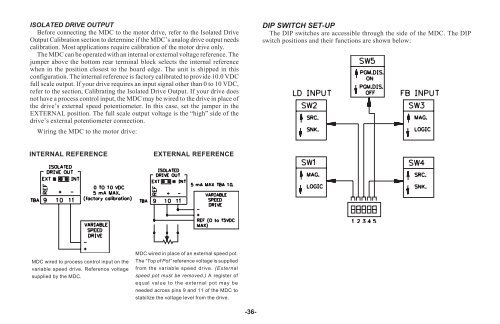
ISOLATED DRIVE OUTPUT<br />
Before connecting the <strong>MDC</strong> to the motor drive, refer to the Isolated Drive<br />
Output Calibration section to determine if the <strong>MDC</strong>’s analog drive output needs<br />
calibration. Most applications require calibration of the motor drive only.<br />
The <strong>MDC</strong> can be operated with an internal or external voltage reference. The<br />
jumper above the bottom rear terminal block selects the internal reference<br />
when in the position closest to the board edge. The unit is shipped in this<br />
configuration. The internal reference is factory calibrated to provide 10.0 VDC<br />
full scale output. If your drive requires an input signal other than 0 to 10 VDC,<br />
refer to the section, Calibrating the Isolated Drive Output. If your drive does<br />
not have a process control input, the <strong>MDC</strong> may be wired to the drive in place of<br />
the drive’s external speed potentiometer. In this case, set the jumper in the<br />
EXTERNAL position. The full scale output voltage is the “high” side of the<br />
drive’s external potentiometer connection.<br />
Wiring the <strong>MDC</strong> to the motor drive:<br />
INTERNAL REFERENCE EXTERNAL REFERENCE<br />
<strong>MDC</strong> wired in place of an external speed pot.<br />
<strong>MDC</strong> wired to process control input on the The “Top of Pot” reference voltage is supplied<br />
variable speed drive. Reference voltage from the variable speed drive. (External<br />
supplied by the <strong>MDC</strong>.<br />
speed pot must be removed.) A register of<br />
equal value to the external pot may be<br />
needed across pins 9 and 11 of the <strong>MDC</strong> to<br />
stabilize the voltage level from the drive.<br />
-36-<br />
DIP SWITCH SET-UP<br />
The DIP switches are accessible through the side of the <strong>MDC</strong>. The DIP<br />
switch positions and their functions are shown below: