MDC Manual 1109KB - Red Lion Controls
MDC Manual 1109KB - Red Lion Controls
MDC Manual 1109KB - Red Lion Controls

You also want an ePaper? Increase the reach of your titles
YUMPU automatically turns print PDFs into web optimized ePapers that Google loves.
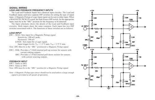
SIGNAL WIRING<br />
LEAD AND FEEDBACK FREQUENCY INPUTS<br />
The Lead and Feedback Inputs have identical input circuitry. The Lead and<br />
Feedback inputs each have separate DIP switches for setting the type of signal<br />
input. A Magnetic Pickup or Logic Input signal can be sent to either input. When<br />
a MAGNETIC PICKUP is used, the Sink/Source DIP switch, for the appropriate<br />
input, must be in the “SRC” position for the frequency to be detected.<br />
The Input schematic shows the details of the Lead and Feedback input<br />
circuitry. Both inputs share the same common. Each input has two DIP<br />
switches associated with it. The functions of these switches are as follows:<br />
LEAD INPUT<br />
SW1 - MAG: Sets input for a Magnetic Pickup signal.<br />
Sensitivity: 200 mV peak;<br />
Hysteresis: 100 mV<br />
LOGIC: Sets input for a Logic signal.<br />
Input trigger levels: VIL = 1.5 V max; VIH = 3.75 V min.<br />
Note: SW2 Must be in the “SRC” position for a Magnetic Pickup signal.<br />
SW2 - SNK: Provides a 7.8 K� internal pull-up resistor for sensors with<br />
current sinking outputs.<br />
SRC: Provides a 3.9 K� internal pull-down resistor for sensors<br />
with current sourcing outputs.<br />
FEEDBACK INPUT<br />
SW3 - Same as SW1<br />
SW4 - Same as SW2<br />
Note: SW4 must be in the “SRC” position for a Magnetic Pickup signal.<br />
Note: A Magnetic Pickup type sensor should not be used unless a large enough<br />
signal is provided at all speeds of operation.<br />
-34-