Teilapparat UT 400 Manual
Teilapparat UT 400 Manual
Teilapparat UT 400 Manual
Create successful ePaper yourself
Turn your PDF publications into a flip-book with our unique Google optimized e-Paper software.
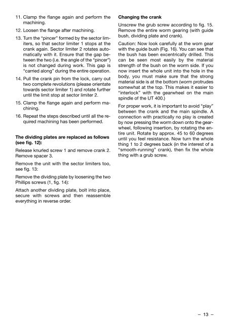
11. Clamp the flange again and perform the<br />
machining.<br />
12. Loosen the flange after machining.<br />
13. Turn the “pincer” formed by the sector limiters,<br />
so that sector limiter 1 stops at the<br />
crank again. Sector limiter 2 rotates automatically<br />
with it. Ensure that the gap between<br />
the two (i.e. the angle of the “pincer”)<br />
is not changed during work. This gap is<br />
“carried along” during the entire operation.<br />
14. Pull the crank pin from the lock, carry out<br />
two complete revolutions (please orientate<br />
towards sector limiter 1) and rotate further<br />
until the limit stop at sector limiter 2.<br />
15. Clamp the flange again and perform ma -<br />
chining.<br />
16. Repeat the steps described until all the required<br />
machining has been performed.<br />
The dividing plates are replaced as follows<br />
(see fig. 12):<br />
Release knurled screw 1 and remove crank 2.<br />
Remove spacer 3.<br />
Remove the unit with the sector limiters too,<br />
see fig. 13:<br />
Remove the dividing plate by loosening the two<br />
Phillips screws (1, fig. 14):<br />
Attach another dividing plate, bolt into place,<br />
secure with screws and then reassemble<br />
everything in reverse order.<br />
Changing the crank<br />
Unscrew the grub screw according to fig. 15.<br />
Remove the entire worm gearing (with guide<br />
bush, dividing plate and crank).<br />
Caution: Now look carefully at the wom gear<br />
with the guide bush (Fig. 16). You can see that<br />
the bush has been excentrically drilled. This<br />
can be seen most easily by the material<br />
strength of the bush on the worm side. If you<br />
now insert the whole unit into the hole in the<br />
body, you must make sure that the strong<br />
material side is at the bottom (worm protrudes<br />
somewhat at the top. This makes it easier to<br />
“interlock” with the gearwheel on the main<br />
spindle of the <strong>UT</strong> <strong>400</strong>.)<br />
For proper work, it is important to avoid “play”<br />
between the crank and the main spindle. A<br />
connection with practically no play is created<br />
by now pressing the worm down onto the gearwheel,<br />
following insertion, by rotating the entire<br />
unit. Rotate by approx. 45 to 60 degrees<br />
until you feel resistance. Now turn the whole<br />
thing 1 to 2 degrees back (in the interest of a<br />
“smooth-running” crank), then fix the whole<br />
thing with a grub screw.<br />
– 13 –


