EN Installation and operation instructions for RADEMACHER X-line ...
EN Installation and operation instructions for RADEMACHER X-line ...
EN Installation and operation instructions for RADEMACHER X-line ...

Sie wollen auch ein ePaper? Erhöhen Sie die Reichweite Ihrer Titel.
YUMPU macht aus Druck-PDFs automatisch weboptimierte ePaper, die Google liebt.
56<br />
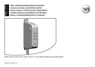
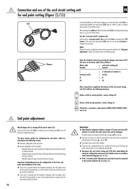
Connection <strong>and</strong> use of the cord circuit setting unit<br />
<strong>for</strong> end point setting (Figure m/n)<br />
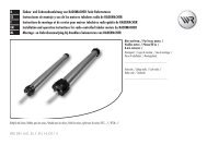
(23)<br />
End point adjustment<br />
Plungers<br />
Mortal danger due to tearing off the motor cable (16).<br />
Ensure that the motor cable (16) is not taken up by the rotating union (5) or torn off<br />
during the configuration process.<br />
You have various options <strong>for</strong> configuring the end points, which are<br />
described in the following section:<br />
◆ Automatic configuration of the end points.<br />
◆ Manual configuration of the end points:<br />
- Manually setting the upper end point <strong>and</strong> setting the lower end point by means<br />
of obstacle detection.<br />
- Setting the upper end point by means of blockage detection <strong>and</strong> manually setting<br />
the lower end point.<br />
- Manually setting the upper end point <strong>and</strong> lower end point.<br />
Important relationship between the configuration of the lower end<br />
point <strong>and</strong> installation of the catch.<br />
◆ If the catch is mounted without the freewheel mechanism, then the tubular motor<br />
will not switch off automatically, as it will not detect an obstacle <strong>and</strong> the lower end<br />
point will not be detected.<br />
◆ If the catch is mounted with the freewheel mechanism, then the tubular motor<br />
will switch off automatically as soon as the freewheel travel is overcome <strong>and</strong> the<br />
roller shutter lamella are closed.<br />
SET<br />
<strong>EN</strong><br />
For initial installation, the roller shutter engineer can connect the motor cable (16) to a<br />
commercially available cord switch device (23) (type no. 4090) in order to configure<br />
the end points <strong>for</strong> the tubular motors.<br />
After mounting, feed cables (e - h) <strong>for</strong> the motor cable (16) to the designated switching<br />
point (e. g. up to the switch socket).<br />
Use the “external switch” conductor (h).<br />
If the conductor “external switch” (h) of motor cable (16) is connected to the “SET<br />
button” of the cord circuit setting device (23), then you can use this set button to<br />
configure the end points.<br />
NOTE<br />
Observe the various configuration options <strong>for</strong> the end points detailed in the “End point<br />
adjustment” chapter (see below) <strong>and</strong> on the following pages.<br />
Open the terminal contacts by pressing the plungers <strong>and</strong> connect all of<br />
the wires of the motor cable (16) as follows:<br />
Motor cable > cord circuit setting unit<br />
Function > Function<br />
L > L1 (direction of rotation 1)<br />
External switch > set <strong>line</strong><br />
N > N<br />
PE > PE<br />
After connection is completed, the buttons of the cord circuit setting<br />
unit (23) will have the following functions:<br />
Rocker switch in central position = motor voltage off<br />
Rocker switch up (s)-position = motor voltage on<br />
SET-button = set button = roller shutters OP<strong>EN</strong>/STOP/DOWN/STOP/<br />
<strong>and</strong> so on.<br />
IMPORTANT<br />
◆ Operating the equipment without a stopper (21) may cause the roller<br />
shutters to run into the roller shutter box <strong>and</strong> be damaged.<br />
The roller shutters must always be fitted with a stopper (21) or end-rail.<br />
◆ End points must be set in order to switch off the motor when they are reached <strong>for</strong><br />
both directions of travel up (s) /down (t).<br />
◆ The tubular motor must be fully installed.<br />
◆ There must be a suitably fixed limit (e.g. window sill) in the area of the lower end<br />
point if the end point is to be configured automatically.<br />
◆ Disconnect the cord circuit setting unit (23) after undertaking the<br />
end point configuration <strong>and</strong> connect the tubular motor in accordance<br />
with connection diagrams (k or l).<br />
◆ If the “external switch” (h) lead is not used, then it must be connected<br />
to the neutral conductor (f), (see fig. k).