EN Installation and operation instructions for RADEMACHER X-line ...
EN Installation and operation instructions for RADEMACHER X-line ...
EN Installation and operation instructions for RADEMACHER X-line ...

Sie wollen auch ein ePaper? Erhöhen Sie die Reichweite Ihrer Titel.
YUMPU macht aus Druck-PDFs automatisch weboptimierte ePaper, die Google liebt.
1.<br />
2.<br />
3.<br />
4.<br />
5.<br />
6.<br />
7.<br />
60<br />
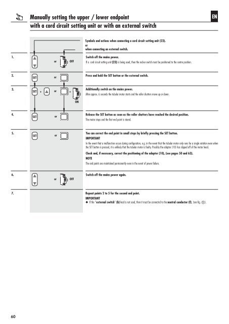
Manually setting the upper / lower endpoint<br />
with a cord circuit setting unit or with an external switch<br />
SET<br />
SET +<br />
SET<br />
SET<br />
or<br />
or<br />
or<br />
or<br />
or<br />
or<br />
OFF<br />
+<br />
OFF<br />
ON<br />
Symbols <strong>and</strong> actions when connecting a cord circuit setting unit (23).<br />
or<br />
when connecting an external switch.<br />
Switch off the mains power.<br />
If a cord circuit setting unit (23) is being used, then the rocker switch must be positioned to the centre position.<br />
Press <strong>and</strong> hold the SET button or the external switch.<br />
Additionally switch on the mains power.<br />
After approx. 6 seconds the tubular motor starts <strong>and</strong> the roller shutters move up or down.<br />
Release the SET button as soon as the roller shutters have reached the desired position.<br />
The motor stops <strong>and</strong> the first end point is stored.<br />
You can correct the end point in small steps by briefly pressing the SET button.<br />
IMPORTANT<br />
In the event that a malfunction occurs during configuration, e.g. in the event that the tubular motor only runs <strong>for</strong> a single rotation even when<br />
the SET button is pressed, it is unlikely that the tubular motor is faulty. Possibly the adapter (10) has slipped off of the motor head.<br />
Check <strong>and</strong>, if necessary, correct the positioning of the adapter (10), (see pages 50 <strong>and</strong> 63).<br />
NOTE<br />
The end points are maintained permanently even in the event of power failure.<br />
Switch off the mains power again.<br />
Repeat points 2 to 5 <strong>for</strong> the second end point.<br />
IMPORTANT<br />
◆ If the “external switch” (h) lead is not used, then it must be connected to the neutral conductor (f), (see fig. k).<br />
<strong>EN</strong>