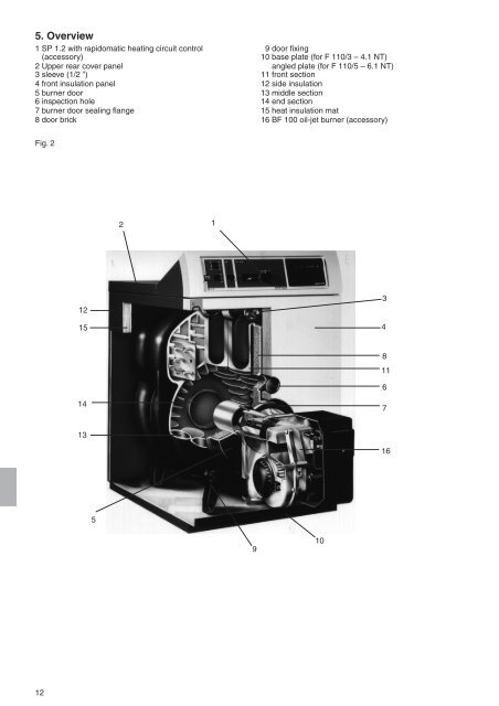
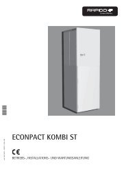
5. Overview 1 SP 1.2 with rapidomatic heating circuit control (accessory) 2 Upper rear cover panel 3 sleeve (1/2 ”) 4 front insulation panel 5 burner door 6 inspection hole 7 burner door sealing flange 8 door brick Fig. 2 12 12 15 14 13 5 2 1 9 9 door fixing 10 base plate (for F <strong>110</strong>/3 – 4.1 <strong>NT</strong>) angled plate (for F <strong>110</strong>/5 – 6.1 <strong>NT</strong>) 11 front section 12 side insulation 13 middle section 14 end section 15 heat insulation mat 16 BF 100 oil-jet burner (accessory) 10 3 4 8 11 6 7 16
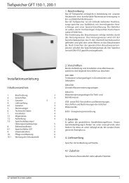
Dimensions Measurements in mm F <strong>110</strong>/3 <strong>NT</strong> 6. Technical data F <strong>110</strong>/4+4.1 <strong>NT</strong> F <strong>110</strong>/5+5.1 <strong>NT</strong> F <strong>110</strong>/6+6.1 <strong>NT</strong> Measurements in mm F <strong>110</strong>/3 <strong>NT</strong> F <strong>110</strong>/4+4.1 <strong>NT</strong> F <strong>110</strong>/5+5.1 <strong>NT</strong> F <strong>110</strong>/6+6.1 <strong>NT</strong> H 910 910 900 900 H 4 517 517 507 507 H 1 760 760 750 750 H 5 75 75 65 65 H 2 305 305 295 295 T 465 595 725 855 H 3 665 665 655 655 D 1 130 130 150 150 thickness of burner door 95 95 95 95 Fig. 3 front view side view from left cleaning lid rear view Type F<strong>110</strong>/3 <strong>NT</strong> F<strong>110</strong>/4 <strong>NT</strong> F<strong>110</strong>/4.1<strong>NT</strong> F<strong>110</strong>/5<strong>NT</strong> F<strong>110</strong>/5.1<strong>NT</strong> F<strong>110</strong>/6<strong>NT</strong> F<strong>110</strong>/6.1<strong>NT</strong> Nominal heating capacity kW 16,0-24,0 24,0-32,0 32,0-40,0 40,0-48,0 48,0-56,0 56,0-64,0 64,0-70,0 Nominal heating load kW 17,5-26,5 26,1-34,9 34,5-43,9 43,7-52,1 51,9-61,5 60,9-69,6 68,9-76,4 Combustion chamber depth mm 265 395 395 525 525 655 655 Heat gas resistance mbar 0,10 0,12 0,14 0,16 0,18 0,20 0,23 Draught pressure mbar 0,10 0,12 0,14 0,16 0,18 0,20 0,23 Boiler gas capacity m 3 Water resistance 0,030 0,044 0,044 0,058 0,058 0,072 0,072 when T = 10 K mbar 2,85 5,04 7,91 11,3 15,5 20,2 25,65 when T = 20 K mbar 0,713 1,260 1,989 2,840 3,875 5,050 6,412 Permitted total excess pressure bar 6 6 6 6 6 6 6 Max. adjustable advance pressure °C 85 85 85 85 85 85 85 Electrical connection V/Hz 230/50 230/50 230/50 230/50 230/50 230/50 230/50 Weight kg 138 173 176 212 217 249 255 Water capacity l 19 26 26 33 33 40 40 Flue gas flow mass** g/s 7,5-11,1 11,1-14,7 14,7-18,6 18,6-22,2 21,9-26,1 25,8-29,4 29,2-33,6 Heating surface m2 0,950 1,443 1,443 1,935 1,935 2,427 2,427 Standby loss % tv 80°C 0,9 0,7 0,7 0,5 0,5 0,27 0,27 tv 40°C 0,3 0,3 0,3 0,2 0,2 0,1 0,1 Gross flue temperature* with 13 % CO2 °C 160-198 160-188 160-193 160-180 160-195 160-176 160-191 Number of radiation converters 4 2 (middle) 4 2 (middle) 4 2 (middle) 4 Flue baffle plate 1 - 1 - - - - Re-circulation pipe 130x140 140x177 140x177 140x177 140x177 - - Water distribution pipe - 1 1 1 1 1 1 Advance connection Rp 11 4 11 4 11 4 1 1 4 11 4 1 1 4 11 4 Back-flow connection Rp 11 4 11 4 11 4 1 1 4 11 4 1 1 4 11 4 CE-product-ID-number CE- CE- CE- CE- CE- CE- CE- 0085AQ1190 0085AQ1190 0085AQ1190 0085AQ1190 0085AQ1190 0085AQ1190 0085AQ1190 *Flue temperature is indicative only. Varying types of fabrication and dirt on heating surfaces can both lead to different values. **Calculated on basis of chimney construction according to DIN 4705, building type-approval identification mark 08-266-342-x DIN registration No. (DIN 4702) K 2066/87. We recommend the use of a burner with oil pre-heating with the F <strong>110</strong>/3 <strong>NT</strong>. 13