F 110 NT - RAPIDO Wärmetechnik GmbH
F 110 NT - RAPIDO Wärmetechnik GmbH
F 110 NT - RAPIDO Wärmetechnik GmbH

Sie wollen auch ein ePaper? Erhöhen Sie die Reichweite Ihrer Titel.
YUMPU macht aus Druck-PDFs automatisch weboptimierte ePaper, die Google liebt.
7. Installation<br />
Installation must be carried out by a qualified technician,<br />
who takes responsibility both for installation and for putting<br />
the unit into operation, as laid down in regulations.<br />
7.1 Connection to water supply<br />
The heating advance and back-flow connections are in the<br />
end section in the upper and lower boiler hub axis extension.<br />
The water distribution pipe drain holes must be lined<br />
up horizontally. A heating back-flow connection must be<br />
pre-fitted to permit filling and draining of the boiler.<br />
The safety valve should be installed in the heating advance,<br />
in the immediate vicinity of the boiler (valid for enclosed<br />
units).<br />
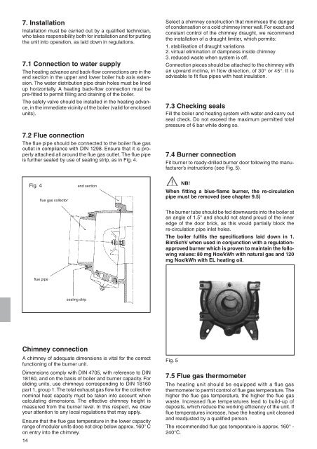
7.2 Flue connection<br />
The flue pipe should be connected to the boiler flue gas<br />
outlet in compliance with DIN 1298. Ensure that it is properly<br />
attached all around the flue gas outlet. The flue pipe<br />
is further sealed by use of sealing strip, as in Fig. 4.<br />
Fig. 4 end section<br />
flue gas collector<br />
flue pipe<br />
sealing strip<br />
Chimney connection<br />
A chimney of adequate dimensions is vital for the correct<br />
functioning of the burner unit.<br />
Dimensions comply with DIN 4705, with reference to DIN<br />
18160, and on the basis of boiler and burner capacity. For<br />
sliding units, use chimneys corresponding to DIN 18160<br />
part 1, group 1. The total exhaust gas flow for the collective<br />
nominal heat capacity must be taken into account when<br />
calculating dimensions. The effective chimney height is<br />
measured from the burner level. In this respect, we draw<br />
your attention to any local regulations that may apply.<br />
Ensure that the flue gas temperature in the lower capacity<br />
range of modular units does not drop below approx. 160° C<br />
on entry into the chimney.<br />
14<br />
Select a chimney construction that minimises the danger<br />
of condensation or a cold chimney inner wall. For exact and<br />
constant control of the chimney draught, we recommend<br />
the installation of a draught limiter, which permits:<br />
1. stabilisation of draught variations<br />
2. virtual elimination of dampness inside chimney<br />
3. reduced waste when system is off.<br />
Connection pieces should be attached to the chimney with<br />
an upward incline, in flow direction, of 30° or 45°. It is<br />
advisable to fit flue pipes with heat insulation.<br />
7.3 Checking seals<br />
Fill the boiler and heating system with water and carry out<br />
seal check. Do not exceed the maximum permitted total<br />
pressure of 6 bar while doing so.<br />
7.4 Burner connection<br />
Fit burner to ready-drilled burner door following the manufacturer’s<br />
instructions (see Fig. 5).<br />
NB!<br />
When fitting a blue-flame burner, the re-circulation<br />
pipe must be removed (see chapter 9.5)<br />
The burner tube should be fed downwards into the boiler at<br />
an angle of 1.5° and should not stand proud of the inner<br />
edge of the door brick, as this would partially block the<br />
re-circulation pipe inlet holes.<br />
The boiler fulfils the specifications laid down in 1.<br />
BimSchV when used in conjunction with a regulationapproved<br />
burner which is proven to maintain the following<br />
values: 80 mg Nox/kWh with natural gas and 120<br />
mg Nox/kWh with EL heating oil.<br />
Fig. 5<br />
7.5 Flue gas thermometer<br />
The heating unit should be equipped with a flue gas<br />
thermometer to permit control of flue gas temperature. The<br />
higher the flue gas temperature, the higher the flue gas<br />
waste. Increased flue temperatures lead to build-up of<br />
deposits, which reduce the working efficiency of the unit. If<br />
flue temperatures increase, have the heating unit cleaned<br />
and readjusted by a qualified person.<br />
The recommended flue gas temperature is approx. 160° -<br />
240°C.