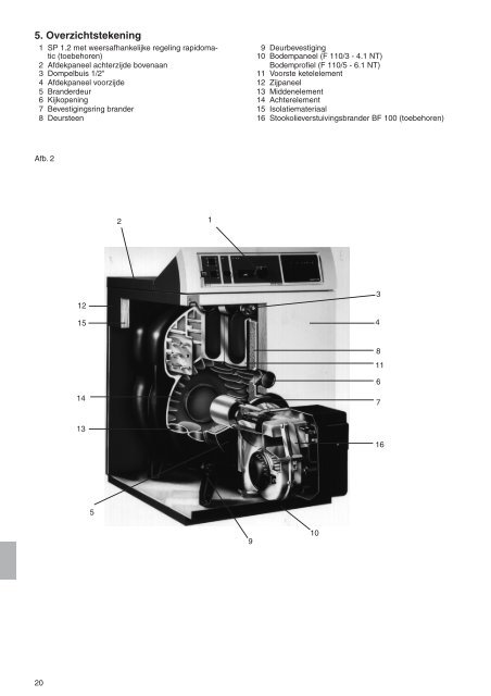
5. Overzichtstekening 1 SP 1.2 met weersafhankelijke regeling rapidomatic (toebehoren) 2 Afdekpaneel achterzijde bovenaan 3 Dompelbuis 1/2" 4 Afdekpaneel voorzijde 5 Branderdeur 6 Kijkopening 7 Bevestigingsring brander 8 Deursteen Afb. 2 20 12 15 14 13 5 2 1 9 9 Deurbevestiging 10 Bodempaneel (F <strong>110</strong>/3 - 4.1 <strong>NT</strong>) Bodemprofiel (F <strong>110</strong>/5 - 6.1 <strong>NT</strong>) 11 Voorste ketelelement 12 Zijpaneel 13 Middenelement 14 Achterelement 15 Isolatiemateriaal 16 Stookolieverstuivingsbrander BF 100 (toebehoren) 10 3 4 8 11 6 7 16
6. Afmetingen Maaten mm F <strong>110</strong>/3 <strong>NT</strong> F <strong>110</strong>/4+4.1 <strong>NT</strong> F <strong>110</strong>/5+5.1 <strong>NT</strong> F <strong>110</strong>/6+6.1 <strong>NT</strong> Maaten mm F <strong>110</strong>/3 <strong>NT</strong> F <strong>110</strong>/4+4.1 <strong>NT</strong> F <strong>110</strong>/5+5.1 <strong>NT</strong> F <strong>110</strong>/6+6.1 <strong>NT</strong> H 910 910 900 900 H 4 517 517 507 507 H 1 760 760 750 750 H 5 75 75 65 65 H 2 305 305 295 295 T 465 595 725 855 H 3 665 665 655 655 D 1 130 130 150 150 Afb. 3 7. Technische gegevens Reinigingsdeksel Vooranzicht Zijaanzicht Achteraanzicht Type F<strong>110</strong>/3 <strong>NT</strong> F<strong>110</strong>/4 <strong>NT</strong> F<strong>110</strong>/4.1<strong>NT</strong> F<strong>110</strong>/5<strong>NT</strong> F<strong>110</strong>/5.1<strong>NT</strong> F<strong>110</strong>/6<strong>NT</strong> F<strong>110</strong>/6.1<strong>NT</strong> Nominale vermogen kW 16,0-24,0 24,0-32,0 32,0-40,0 40,0-48,0 48,0-56,0 56,0-64,0 64,0-70,0 Nominale belasting kW 17,5-26,5 26,1-34,9 34,5-43,9 43,7-52,1 51,9-61,5 60,9-69,6 68,9-76,4 Branderkamer diepde mm 265 395 395 525 525 655 655 Rookgaszijdige weerstand mbar 0,10 0,12 0,14 0,16 0,18 0,20 0,23 Vereiste schoorsteentrek mbar 0,10 0,12 0,14 0,16 0,18 0,20 0,23 Inhoud vuurhaard en kanalen m3 Waterzijdige weerstand 0,030 0,044 0,044 0,058 0,058 0,072 0,072 bij T = 10 K mbar 2,85 5,04 7,91 11,3 15,5 20,2 25,65 bij T = 20 K mbar 0,713 1,260 1,989 2,840 3,875 5,050 6,412 Max. toelaatbare overdruk bar 6 6 6 6 6 6 6 Max. aavoertempertuur °C 85 85 85 85 85 85 85 Elektrische aansluiting V/Hz 230/50 230/50 230/50 230/50 230/50 230/50 230/50 Gewicht kg 138 173 176 212 217 249 255 Waterinhoud l 19 26 26 33 33 40 40 Rookgasvolumestroom ** g/s 7,5-11,1 11,1-14,7 14,7-18,6 18,6-22,2 21,9-26,1 25,8-29,4 29,2-33,6 Verwarmingsoppervlak m2 0,950 1,443 1,443 1,935 1,935 2,427 2,427 Stillstndsverlies % tv 80°C 0,9 0,7 0,7 0,5 0,5 0,27 0,27 tv 40°C 0,3 0,3 0,3 0,2 0,2 0,1 0,1 Rookgastemperatuur * bruto bij 13 % CO2 °C 160-198 160-188 160-193 160-180 160-195 160-176 160-191 Aantal remplaten 4 2 (Mitte) 4 2 (Mitte) 4 2 (Mitte) 4 Rookgasgeleider 1 - 1 - - - - Recirculatiebuis 130x140 140x177 140x177 140x177 140x177 - - Retourverdeelpijp - 1 1 1 1 1 1 Aansluiting vertrek Rp 11 4 11 4 11 4 1 1 4 11 4 1 1 4 11 4 Aansluiting retour Rp 11 4 11 4 11 4 1 1 4 11 4 1 1 4 11 4 CE-product-Ident.-Nr. CE- CE- CE- CE- CE- CE- CE- 0085AQ1190 0085AQ1190 0085AQ1190 0085AQ1190 0085AQ1190 0085AQ1190 0085AQ1190 * De Rookgastemperatuur is een richtwaard, die door vervuiling van de warmteoverdrachtvlakken en het fabrikaat van de brander wordt beinvloed. **Reekenwaarde voor de bereekening van de schoorsteen volgens DIN 4705. Bij de F <strong>110</strong>/3 <strong>NT</strong>T raden we aan een oliebrander met olievoorverwarming te gebruiken. 21