DS TECH Katalog_Schneckengetriebe_kl
DS TECH Katalog_Schneckengetriebe_kl
DS TECH Katalog_Schneckengetriebe_kl

Sie wollen auch ein ePaper? Erhöhen Sie die Reichweite Ihrer Titel.
YUMPU macht aus Druck-PDFs automatisch weboptimierte ePaper, die Google liebt.
®<br />
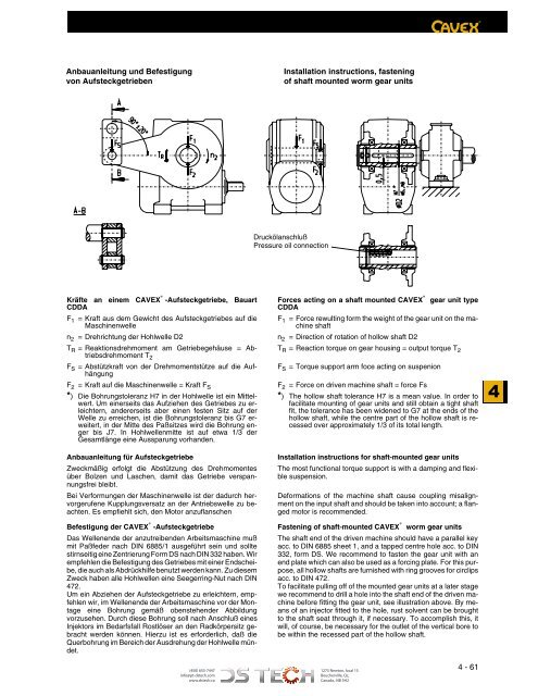
Anbauanleitung und Befestigung<br />
von Aufsteckgetrieben<br />
Installation instructions, fastening<br />
of shaft mounted worm gear units<br />
*<br />
Druckölanschluß<br />
Pressure oil connection<br />
Kräfte an einem CAVEX ® -Aufsteckgetriebe, Bauart<br />
CDDA<br />
F 1 = Kraft aus dem Gewicht des Aufsteckgetriebes auf die<br />
Maschinenwelle<br />
Forces acting on a shaft mounted CAVEX ® gear unit type<br />
CDDA<br />
F 1 = Force rewulting form the weight of the gear unit on the machine<br />
shaft<br />
n 2<br />
2D el lewlhoH n2 red = Direction gnuthcirherD=<br />
of rotation of hollow shaft D2<br />
T R = Reaktionsdrehmoment am Getriebegehäuse = Abtriebsdrehmoment<br />
T<br />
T R = Reaction torque on gear housing = output torque T 2<br />
2<br />
F S = Abstützkraft von der Drehmomentstütze auf die Aufhängung<br />
F 2 = Kraft auf die Maschinenwelle = Kraft F S<br />
*) Die Bohrungstoleranz H7 in der Hohlwelle ist ein Mittelwert.<br />
Um einerseits das Aufziehen des Getriebes zu erleichtern,<br />
andererseits aber einen festen Sitz auf der<br />
Welle zu erreichen, ist die Bohrungstoleranz bis G7 erweitert,<br />
in der Mitte des Paßsitzes wird die Bohrung enger<br />
bis J7. In Hohlwellenmitte ist auf etwa 1/3 der<br />
Gesamtlänge eine Aussparung vorhanden.<br />
F S = Torque support arm foce acting on suspenion<br />
F 2 = Force on driven machine shaft = force Fs<br />
*) The hollow shaft tolerance H7 is a mean value. In order to<br />
facilitate mounting of gear units and still obtain a tight shaft<br />
fit, the tolerance has been widened to G7 at the ends of the<br />
hollow shaft, while the centre part of the hollow shaft is recessed<br />
over approximately 1/3 of its total length.<br />
4<br />
Zweckmäßig erfolgt die Abstützung des Drehmomentes<br />
über Bolzen und Laschen, damit das Getriebe verspannungsfrei<br />
bleibt.<br />
Bei Verformungen der Maschinenwelle ist der dadurch hervorgerufene<br />
Kupplungsversatz an der Antriebswelle zu beachten.<br />
Es empfiehlt sich, den Motor anzuflanschen<br />
ebeirtegkcetsfuA rüf oitallatsnI<br />
n instructions gnutielnauabnA<br />
for shaft-mounted gear units<br />
The most functional torque support is with a damping and flexible<br />
suspension.<br />
Deformations of the machine shaft cause coupling misalignment<br />
on the input shaft and should be taken into account; a flanged<br />
motor is recommended.<br />
Befestigung der CAVEX ® -Aufsteckgetriebe Fastening of shaft-mounted CAVEX ® worm gear units<br />
Das Wellenende der anzutreibenden Arbeitsmaschine muß<br />
mit Paßfeder nach DIN 6885/1 ausgeführt sein und sollte<br />
stirnseitig eine Zentrierung Form <strong>DS</strong> nach DIN 332 haben. Wir<br />
empfehlen die Befestigung des Getriebes mit einer Endscheibe,<br />
die auch als Abdrückhilfe benutzt werden kann. Zu diesem<br />
Zweck haben alle Hohlwellen eine Seegerring-Nut nach DIN<br />
472.<br />
Um ein Abziehen der Aufsteckgetriebe zu erleichtern, empfehlen<br />
wir, im Wellenende der Arbeitsmaschine vor der Montage<br />
eine Bohrung gemäß obenstehender Abbildung<br />
vorzusehen. Durch diese Bohrung soll nach Anschluß eines<br />
Injektors im Bedarfsfall Rostlöser an den Radkörpersitz gebracht<br />
werden können. Hierzu ist es erforderlich, daß die<br />
Querbohrung im Bereich der Ausdrehung der Hohlwelle mündet.<br />
The shaft end of the driven machine should have a parallel key<br />
acc. to DIN 6885 sheet 1, and a tapped centre hole acc. to DIN<br />
332, form <strong>DS</strong>. We recommend to fasten the gear unit with an<br />
end plate which can also be used as a forcing plate. For this purpose,<br />
all hollow shafts are furnished with ring grooves for circlips<br />
acc. to DIN 472.<br />
To facilitate pulling off of the mounted gear units at a later stage<br />
we recommend to drill a hole into the shaft end of the driven machine<br />
before fitting the gear unit, see illustration above. By means<br />
of an injector fitted to the hole, rust solvent can be brought<br />
to the shaft seat through it, if necessary. To accomplish this, it<br />
will, of course, be necessary for the outlet of the vertical bore to<br />
be within the recessed part of the hollow shaft.<br />
(450) 655-7447<br />
info@pt-dstech.com<br />
www.dstech.ca<br />
1275 Newton, local 15<br />
Boucherville, Qc,<br />
Canada, J4B 5H2<br />
4 - 61