DS TECH Katalog_Schneckengetriebe_kl
DS TECH Katalog_Schneckengetriebe_kl
DS TECH Katalog_Schneckengetriebe_kl

Sie wollen auch ein ePaper? Erhöhen Sie die Reichweite Ihrer Titel.
YUMPU macht aus Druck-PDFs automatisch weboptimierte ePaper, die Google liebt.
®<br />
Charakteristische Vorzüge<br />
Prinzip der Verzahnung<br />
Die Hohlflanken-Zylinderschnecke mit ihrem globoidischen<br />
Schneckenrad weist gegenüber den üblichen Ausführungen<br />
einen wesentlichen Unterschied auf.<br />
Die Schneckenzähne haben konkaves Flankenprofil (Hohlflankenschnecke)<br />
anstelle eines geraden oder konvexen. Dadurch<br />
ergeben sich besondere Vorzüge, die des leichteren<br />
Verständnisses wegen stark vereinfacht dargestellt und erläutert<br />
sind.<br />
Bei der Hohlflanken-Verzahnung tritt eine geringe spezifische<br />
Flankenpressung (Hertz'sche Pressung) auf, und die Aufrechterhaltung<br />
eines trennenden Ölfilms zwischen den Zahnflanken<br />
wird besonders begünstigt, weil sich Hohlflanken mit<br />
balligen Gegenflanken berühren. Die Flankenschmiegung ist<br />
also sehr viel günstiger als bei sonst üblichen Verzahnungen,<br />
bei denen ballige Zahnflanken mit balligen Gegenflanken zum<br />
Eingriff kommen.<br />
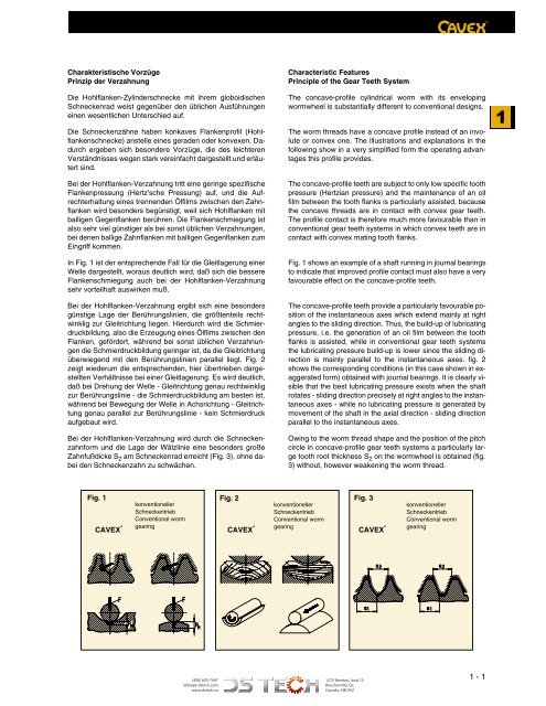
In Fig. 1 ist der entsprechende Fall für die Gleitlagerung einer<br />
Welle dargestellt, woraus deutlich wird, daß sich die bessere<br />
Flankenschmiegung auch bei der Hohlflanken-Verzahnung<br />
sehr vorteilhaft auswirken muß.<br />
Bei der Hohlflanken-Verzahnung ergibt sich eine besonders<br />
günstige Lage der Berührungslinien, die größtenteils rechtwin<strong>kl</strong>ig<br />
zur Gleitrichtung liegen. Hierdurch wird die Schmierdruckbildung,<br />
also die Erzeugung eines Ölfilms zwischen den<br />
Flanken, gefördert, während bei sonst üblichen Verzahnungen<br />
die Schmierdruckbildung geringer ist, da die Gleitrichtung<br />
überwiegend mit den Berührungslinien parallel liegt. Fig. 2<br />
zeigt wiederum die entsprechenden, hier übertrieben dargestellten<br />
Verhältnisse bei einer Gleitlagerung. Es wird deutlich,<br />
daß bei Drehung der Welle - Gleitrichtung genau rechtwin<strong>kl</strong>ig<br />
zur Berührungslinie - die Schmierdruckbildung am besten ist,<br />
während bei Bewegung der Welle in Achsrichtung - Gleitrichtung<br />
genau parallel zur Berührungslinie - kein Schmierdruck<br />
aufgebaut wird.<br />
Bei der Hohlflanken-Verzahnung wird durch die Schneckenzahnform<br />
und die Lage der Wälzlinie eine besonders große<br />
Zahnfußdicke S 2 am Schneckenrad erreicht (Fig. 3), ohne dabei<br />
den Schneckenzahn zu schwächen.<br />
Characteristic Features<br />
Principle of the Gear Teeth System<br />
The concave-profile cylindrical worm with its enveloping<br />
wormwheel is substantially different to conventional designs.<br />
The worm threads have a concave profile instead of an involute<br />
or convex one. The illustrations and explanations in the<br />
following show in a very simplified form the operating advantages<br />
this profile provides.<br />
The concave-profile teeth are subject to only low specific tooth<br />
pressure (Hertzian pressure) and the maintenance of an oil<br />
film between the tooth flanks is particularly assisted, because<br />
the concave threads are in contact with convex gear teeth.<br />
The profile contact is therefore much more favourable than in<br />
conventional gear teeth systems in which convex teeth are in<br />
contact with convex mating tooth flanks.<br />
Fig. 1 shows an example of a shaft running in journal bearings<br />
to indicate that improved profile contact must also have a very<br />
favourable effect on the concave-profile teeth.<br />
The concave-profile teeth provide a particularly favourable position<br />
of the instantaneous axes which extend mainly at right<br />
angles to the sliding direction. Thus, the build-up of lubricating<br />
pressure, i.e. the generation of an oil film between the tooth<br />
flanks is assisted, while in conventional gear teeth systems<br />
the lubricating pressure build-up is lower since the sliding direction<br />
is mainly parallel to the instantaneous axes. fig. 2<br />
shows the corresponding conditions (in this case shown in exaggerated<br />
form) obtained with journal bearings. It is clearly visible<br />
that the best lubricating pressure exists when the shaft<br />
rotates - sliding direction precisely at right angles to the instantaneous<br />
axes - while no lubricating pressure is generated by<br />
movement of the shaft in the axial direction - sliding direction<br />
parallel to the instantaneous axes.<br />
Owing to the worm thread shape and the position of the pitch<br />
circle in concave-profile gear teeth systems a particularly large<br />
tooth root thickness S 2 on the wormwheel is obtained (fig.<br />
3) without, however weakening the worm thread.<br />
1<br />
Fig. 1 Fig. 2 Fig. 3<br />
CAVEX ® konventioneller<br />
Schneckentrieb<br />
Conventional worm<br />
gearing<br />
CAVEX ® konventioneller<br />
Schneckentrieb<br />
Conventional worm<br />
gearing<br />
CAVEX ®<br />
konventioneller<br />
Schneckentrieb<br />
Conventional worm<br />
gearing<br />
(450) 655-7447<br />
info@pt-dstech.com<br />
www.dstech.ca<br />
1275 Newton, local 15<br />
Boucherville, Qc,<br />
Canada, J4B 5H2<br />
1 - 1