

o_19jdnovcg1eh21852116govv1lgra.pdf

Erfolgreiche ePaper selbst erstellen
Machen Sie aus Ihren PDF Publikationen ein blätterbares Flipbook mit unserer einzigartigen Google optimierten e-Paper Software.
Structural Report<br />
The geometry of the truss riggs is adapted individually to the<br />
needs of the event. Usually the suspension points are<br />
determined by the event location. The precise suspension<br />
possibilities with the according load limits have to be known<br />
before the hanging of a rigg. This informations should be<br />
provided in written form by the management of the hall.<br />
If this information is not available it has to be calculated on<br />
the basis of the existing structural report of the hall. Additional<br />
loads should not be applicated on an existing construction<br />
without further examination / structural analysis.<br />
SUSPENDED TRUSS<br />
dynamic increase factors. Particularly fast moving systems or<br />
systems with loads that are moved above persons should be<br />
calculated with a higher increase factor.<br />
Attachment gears:<br />
The load bearing capacities of attachment gears are given by the<br />
manufacturer. The maximum utilization is limited to 50 . For example<br />
for wire ropes a utilization coefficient of 5 is required, according<br />
to BGV C1 this value has to be doubled again.<br />
As stated above only very simple constructions with defined<br />
boundary conditions can be dimensioned by using the<br />
manufacurer's information.<br />
Usually these informations are restricted to a single span<br />
beam with uniformly distributed loading or a single load in<br />
the middle of the beam. But already the two-span beam -<br />
a simple system - can not be measured this way.<br />
In the following two examples for explanation (single- and<br />
two-span beam):<br />
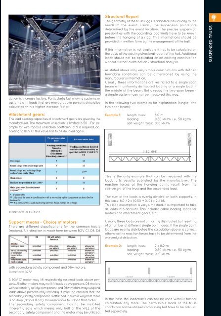
Example 1: length truss: 8.0 m<br />
loading: 0.50 kN/m i.e. 50 kg/m<br />
self-weight truss: 0,10 kN/m<br />
This is the only example that can be measured with the<br />
loadcharts usually published by the manufacturer. The<br />
reaction forces at the hanging points result from the<br />
self-weight of the truss and the suspended load.<br />
Excerpt from the BGI 810-3<br />
Support means - Choice of motors<br />
There are different classifications for the common hoists<br />
(motors). A distinction is made here between BGV C1, D8, D8<br />
The sum of the loads is evenly divided on both supports, in<br />
this case: 8.0 / 2 x (0.50 + 0.10) = 2.4 kN.<br />
This load assumption is very simplified. It is important to take<br />
all loads into account. This includes cable loading, loads for<br />
motors and attachment gears, etc.<br />
Usually these loads are not uniformly distributed but resulting<br />
of a number of different single point loads. If the single point<br />
loads are evenly distributed the calculation above is correct,<br />
otherwise the reaction forces have to be determined from the<br />
unevenly distribution.<br />
Example 2: length truss: 2 x 8.0 m<br />
loading: 0.50 kN/m i.e. 50 kg/m<br />
self-weight truss: 0.10 kN/m<br />
with secondary safety component and D8+ motors.<br />
Excerpt from SQ P2<br />
A BGV C1 motor may lift respectively suspend loads above persons.<br />
All other motors may not lift loads above persons. D8 motors<br />
with secondary safety component and D8+ motors may suspend<br />
loads above persons only statically. It must be ensured that the<br />
secondary safety component is attached in such a way that there<br />
is no drop (drop = 0 cm). It is reasonable to unload that motor.<br />
The secondary safety component has to be installed<br />
inherently safe which means only half of the WLL of the<br />
secondary safety component and the motor may be utilized.<br />
In this case the loadcharts can not be used without further<br />
calculation any more. The permissible loads of the truss<br />
charts can not be utilized completely but have to be calculated<br />
seperately.<br />
207