

o_19jdnovcg1eh21852116govv1lgra.pdf

Erfolgreiche ePaper selbst erstellen
Machen Sie aus Ihren PDF Publikationen ein blätterbares Flipbook mit unserer einzigartigen Google optimierten e-Paper Software.
case, which is why usually a limiting of<br />
the wind force in operation mode is not<br />
possible.<br />
LED display 5 x 3.0 m erected<br />
Base a = 3.0 m<br />
For wind force > 8<br />
required ballast at A → 960 kg<br />
required ballast at B → no ballast<br />
A further comparison shows the influence<br />
of a reduced base on the ballast:<br />
LED display 5 x 3.0 m erected<br />
Base a = 1.50 m<br />
required ballast at A → 1920 kg<br />
required ballast at B → 820 kg<br />
Indoor riggs<br />
For indoor use horizontal compensation<br />
loads for inclination, stabilization<br />
loads and/or loads for impact of persons<br />
have to be taken into account for<br />
the bracing. (In the meantime for some<br />
exhibition halls a proof of stability for<br />
limited hall wind loads is required.<br />
These loads have to be understood as<br />
horizontal compensation loads.)<br />
The systems correspond to the outdoor<br />
riggs.<br />
Furthermore it should be noted that a<br />
frame construction only with ‘sleeveblocks’<br />
is not sufficient indoor, too. The<br />
guiding pulleys usually have so much<br />
clearance that they only have contact<br />
after tilting of the column. Additionally<br />
the stress of transverse bending would<br />
have to be verified, that results from<br />
the contact of the guiding pulleys to<br />
the truss under bending.<br />
For these riggs the minimum horizontal<br />
load for unintentional inclination is:<br />
H = V / 200 and<br />
V / 100 simplified as V / 50<br />
It should be kept in mind that columns<br />
on base plates with small dimensions<br />
stand on their own but get already<br />
instable at a slight addition of horizontal<br />
loads.<br />
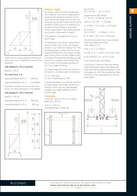
Example<br />
Columns: truss w= 35 cm on base<br />
plate 40 x 40 cm:<br />
with h = 3.50 m<br />
average height of the rig<br />
by crowd:<br />
Hs > 0.5 kN at h = 1,0 m<br />
payload and self weight:<br />
V = 2.0 /2 = 1,0 kN per column<br />
with H = 1.0 / 50 = 0.02 kN<br />
A. → Mtilt = 3.5 x 0,02 = 0.07 kNm<br />
by crowd<br />
Hs > 0.5 kN in Höhe h = 1.0 m<br />
B. → Mtilt = 0.5 x 1.0 = 0.50 kNm<br />
the tilting moment has to be smaller<br />
than the stablity moment<br />
with safety of 1.3:<br />
Mtilt x 1.3 < V x 0.18 m<br />
A: 0.07 x 1.3 = 0.091 < 1.0 x 0.18 = 0.18<br />
B. (0.07+0.5) x 1.3 = 0.74 >> 0.18<br />
Four times below the safety!<br />
Conclusion: Columns that are restrained<br />
at the base have to be designed<br />
with sufficiently stable basement with<br />
outriggers or with the possibility of ballasting<br />
or with a plugged and ‘strong’<br />
base plate.<br />
GROUND SUPPORT<br />
Autoren:<br />
Frank Bastians, Stefan Krasenbrink, Jan Keppler, Ralf-Harald vom Felde.<br />
Weitere Informationen gibt es von den Autoren unter:<br />
www.krasenbrink-bastians.de sowie www.vom-felde.de<br />
213