

o_19jdnovcg1eh21852116govv1lgra.pdf

Sie wollen auch ein ePaper? Erhöhen Sie die Reichweite Ihrer Titel.
YUMPU macht aus Druck-PDFs automatisch weboptimierte ePaper, die Google liebt.
permissible MEch = approx. 20-70<br />
permissible Mtruss (experience)<br />
The principle is a “deviation” of the<br />
bending as compressive and tensile<br />
forces via the diagonal brace (see<br />
below).<br />
couplers with force transmission by<br />
friction (slipping). As a makeshift approved<br />
values of<br />
scaffolding are used (e.g. Layher), but<br />
this approach has to be agreed with<br />
the responsible authority<br />
e. Transverse bending of the main<br />
chords of the truss. In this case it<br />
should be tried to keep the distance to<br />
the bracings of the truss short. From<br />
the compressive force in the diagonal<br />
pipe and the eccentricity A (see illustration<br />
below) results local transverse<br />
bending in the main chords of the column,<br />
which reduces the load bearing<br />
capacity greatly. (Caution: this transverse<br />
bending (the resulting stress)<br />
alone may lead to a failure of the truss)<br />
D. Cross bracing with ropes<br />
In this case it is important that there<br />
are three independent wall bracings<br />
with crossed ropes as it is done at<br />
stage<br />
constructions, and the roof level is designed<br />
as a plate with bracings of crossed<br />
ropes and possibly with pressure<br />
tubes. Alternatively the girder grid can<br />
be braced by bending resistant horizontal<br />
corners.<br />
GROUND SUPPORT<br />
2. ‘Welded corners’ – unbraced corners<br />
These are usually ‘decoration’-trusses<br />
with somehow placed diagonal bracings.<br />
If the construction is unfavorable<br />
as shown in the illustration the absorbable<br />
moment declines to the comparatively<br />
small bending load bearing<br />
capacity of the main chords.<br />
MEch = approx. 5 - 10 Mtruss<br />
(experience)<br />
It has to be noted that due to the<br />
frame effect horizontal forces at the<br />
base point and corner moments result<br />
from<br />
vertical loadings at the rig. This also<br />
applies for the following system (B).<br />
B. Corners braced by coupled pipes<br />
This version can be used for example if<br />
the girder grid is hoisted with ‘sleeve<br />
blocks’.<br />
The resisting moment is dependent on:<br />
a. The lever arm of the diagonal pipe<br />
(to the corner)<br />
b. The permissible compressive force<br />
of the pipes (the longer the pipe the<br />
lower the permissible force due to<br />
buckling)<br />
c. A symmetrical installation of the<br />
pipes (on both sides)<br />
d. The permissible connection forces<br />
for example of a swivel coupler. The<br />
problem in this regard is that there is<br />
no official approval in Germany for<br />
Furthermore of importance is that the<br />
sleeveblock is interlocked, for example<br />
with a socket at the column that is interlocked<br />
with a pipe or hanging in a<br />
chain attached above with couplers<br />
and pipes.<br />
C. Bending resistant connection to the<br />
basements and/or the extension arms<br />
The stability of the column fixed at the<br />
base is dependent on the ratio tilting<br />
moment - stability moment. Figuratively<br />
speaking this means, that the H-forces<br />
want to tip the column over the basis.<br />
That means the column needs a basement<br />
with sufficient width and ballast<br />
and/or additional extension arms.<br />
Decisive for the stability of the column<br />
are therefore usually the dimensions of<br />
the basement (L), how solid the basement<br />
is built and the self weight of the<br />
total construction including the ballast.<br />
Only for very solid basements the<br />
weak point is the tower itself.<br />
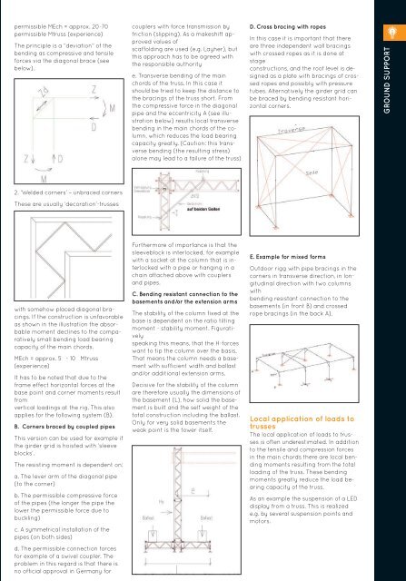
E. Example for mixed forms<br />
Outdoor rigg with pipe bracings in the<br />
corners in transverse direction, in longitudinal<br />
direction with two columns<br />
with<br />
bending resistant connection to the<br />
basements (in front B) and crossed<br />
rope bracings (in the back A).<br />
Local application of loads to<br />
trusses<br />
The local application of loads to trusses<br />
is often underestimated. In addition<br />
to the tensile and compression forces<br />
in the main chords there are local bending<br />
moments resulting from the total<br />
loading of the truss. These bending<br />
moments greatly reduce the load bearing<br />
capacity of the truss.<br />
As an example the suspension of a LED<br />
display from a truss. This is realized<br />
e.g. by several suspension points and<br />
motors.<br />
211