Hochdruckschwimmer- Regler Montage- und ... - KomMa
Hochdruckschwimmer- Regler Montage- und ... - KomMa
Hochdruckschwimmer- Regler Montage- und ... - KomMa

Sie wollen auch ein ePaper? Erhöhen Sie die Reichweite Ihrer Titel.
YUMPU macht aus Druck-PDFs automatisch weboptimierte ePaper, die Google liebt.
6.4.3 Automatische Ventile in der Zulaufleitung 6.4.3 Automatic valves in the liquid feed line<br />
Automatische Ventile sind in der Zulaufleitung gr<strong>und</strong>sätzlich<br />
zu vermeiden. Sollten diese dennoch benötigt werden, empfehlen<br />
sich z.B. elektrisch oder pneumatisch betriebene Kugelhähne.<br />
Differenzdruckabhängige Ventile (z.B. Pilotventile) sind wegen<br />
fehlender Druckdifferenz zwischen Verflüssiger <strong>und</strong><br />
<strong>Regler</strong> ungeeignet.<br />
The use of automatic valves in the liquid feed line should<br />
generally be avoided. If they are absolutely necessary, it<br />
is recommended to use e.g. electrically or pneumatically<br />
operated full bore ball valves.<br />
Any valves depending on a pressure difference (e.g. pilot<br />
valves) are unsuitable because of the lack of pressure<br />
difference between condenser and float regulator.<br />
6.4.4 Anschluss an Plattenverflüssiger 6.4.4 Connection to plate condensers<br />
Wenn kein HS-<strong>Regler</strong> ohne Unterdruckdüse verwendet werden<br />
kann (z.B. wenn der <strong>Regler</strong> nicht unter dem Verflüssiger<br />
angeordnet werden kann), ist folgendes zu beachten:<br />
Besonders bei Plattenwärmetauschern, die nur eine<br />
geringe Kältemittelfüllung haben, ist darauf zu achten,<br />
dass kein Gas zu dem <strong>Regler</strong> gelangen kann.<br />
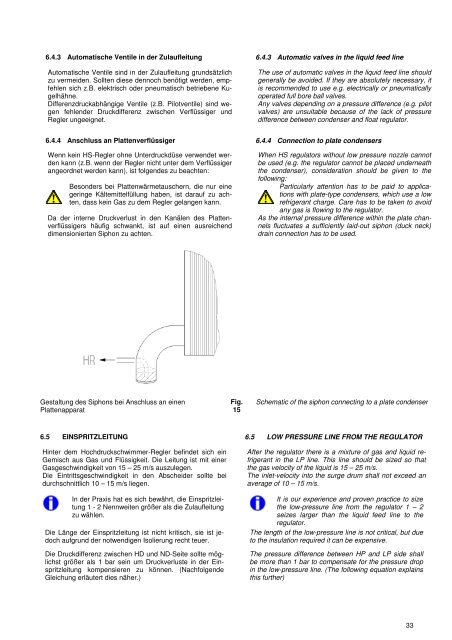
Da der interne Druckverlust in den Kanälen des Plattenverflüssigers<br />
häufig schwankt, ist auf einen ausreichend<br />
dimensionierten Siphon zu achten.<br />
When HS regulators without low pressure nozzle cannot<br />
be used (e.g. the regulator cannot be placed <strong>und</strong>erneath<br />
the condenser), consideration should be given to the<br />
following:<br />
Particularly attention has to be paid to applications<br />
with plate-type condensers, which use a low<br />
refrigerant charge. Care has to be taken to avoid<br />
any gas is flowing to the regulator.<br />
As the internal pressure difference within the plate channels<br />
fluctuates a sufficiently laid-out siphon (duck neck)<br />
drain connection has to be used.<br />
Gestaltung des Siphons bei Anschluss an einen<br />
Plattenapparat<br />
Fig.<br />
15<br />
Schematic of the siphon connecting to a plate condenser<br />
6.5 EINSPRITZLEITUNG 6.5 LOW PRESSURE LINE FROM THE REGULATOR<br />
Hinter dem <strong>Hochdruckschwimmer</strong>-<strong>Regler</strong> befindet sich ein<br />
Gemisch aus Gas <strong>und</strong> Flüssigkeit. Die Leitung ist mit einer<br />
Gasgeschwindigkeit von 15 – 25 m/s auszulegen.<br />
Die Eintrittsgeschwindigkeit in den Abscheider sollte bei<br />
durchschnittlich 10 – 15 m/s liegen.<br />
In der Praxis hat es sich bewährt, die Einspritzleitung<br />
1 - 2 Nennweiten größer als die Zulaufleitung<br />
zu wählen.<br />
Die Länge der Einspritzleitung ist nicht kritisch, sie ist jedoch<br />
aufgr<strong>und</strong> der notwendigen Isolierung recht teuer.<br />
Die Druckdifferenz zwischen HD <strong>und</strong> ND-Seite sollte möglichst<br />
größer als 1 bar sein um Druckverluste in der Einspritzleitung<br />
kompensieren zu können. (Nachfolgende<br />
Gleichung erläutert dies näher.)<br />
After the regulator there is a mixture of gas and liquid refrigerant<br />
in the LP line. This line should be sized so that<br />
the gas velocity of the liquid is 15 – 25 m/s.<br />
The inlet-velocity into the surge drum shall not exceed an<br />
average of 10 – 15 m/s.<br />
It is our experience and proven practice to size<br />
the low-pressure line from the regulator 1 – 2<br />
seizes larger than the liquid feed line to the<br />
regulator.<br />
The length of the low-pressure line is not critical, but due<br />
to the insulation required it can be expensive.<br />
The pressure difference between HP and LP side shall<br />
be more than 1 bar to compensate for the pressure drop<br />
in the low-pressure line. (The following equation explains<br />
this further)<br />
33