Hochdruckschwimmer- Regler Montage- und ... - KomMa
Hochdruckschwimmer- Regler Montage- und ... - KomMa
Hochdruckschwimmer- Regler Montage- und ... - KomMa

Sie wollen auch ein ePaper? Erhöhen Sie die Reichweite Ihrer Titel.
YUMPU macht aus Druck-PDFs automatisch weboptimierte ePaper, die Google liebt.
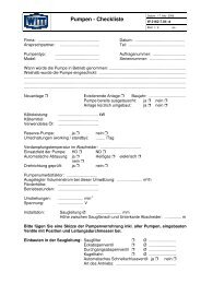
Fig. 16 a<br />
HR1 – HR3 (Siehe hierzu auch Fig. 16a <strong>und</strong> 16b)<br />
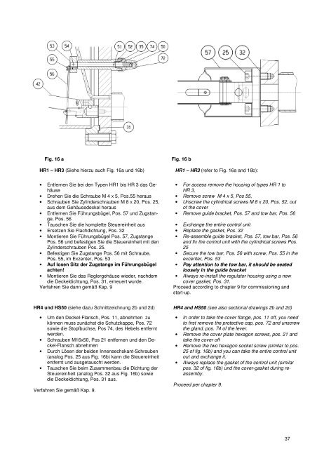
Fig. 16 b<br />
HR1 – HR3 (refer to Fig. 16a and 16b):<br />
• Entfernen Sie bei den Typen HR1 bis HR 3 das Gehäuse<br />
• Drehen Sie die Schraube M 4 x 5, Pos.55 heraus<br />
• Schrauben Sie Zylinderschrauben M 8 x 20, Pos. 25,<br />
aus dem Gehäusedeckel heraus<br />
• Entfernen Sie Führungsbügel, Pos. 57 <strong>und</strong> Zugstange,<br />
Pos. 56<br />
• Tauschen Sie die komplette Steuereinheit aus<br />
• Ersetzen Sie Flachdichtung, Pos. 32<br />
• Montieren Sie Führungsbügel Pos. 57, Zugstange<br />
Pos. 56 <strong>und</strong> befestigen Sie die Steuereinheit mit den<br />
Zylinderschrauben Pos. 25.<br />
• Befestigen Sie Zugstange Pos. 56 mit Schraube,<br />
Pos. 55, im Exzenter, Pos. 53<br />
• Auf losen Sitz der Zugstange im Führungsbügel<br />
achten!<br />
• Montieren Sie das <strong>Regler</strong>gehäuse wieder, nachdem<br />
die Deckeldichtung, Pos. 31, erneuert wurde.<br />
Verfahren Sie dann gemäß Kap. 9<br />
• For access remove the housing of types HR 1 to<br />
HR 3,<br />
• Remove screw M 4 x 5, Pos 55,<br />
• Unscrew the cylindrical screws M 8 x 20, Pos. 52, out<br />
of the cover<br />
• Remove guide bracket, Pos. 57 and tow bar, Pos. 56<br />
• Exchange the entire control unit<br />
• Replace the gasket, Pos. 32<br />
• Re-assemble guide bracket, Pos. 57, tow bar, Pos. 56<br />
and fix the control unit with the cylindrical screws Pos.<br />
25<br />
• Secure the tow bar, Pos. 56 with screw, Pos. 55 in the<br />
excenter, Pos. 53<br />
• Pay attention to the tow bar, it should be seated<br />
loosely in the guide bracket<br />
• Always re-install the regulator housing using a new<br />
cover gasket, Pos. 31.<br />
Proceed according to chapter 9 for commissioning and<br />
start-up.<br />
HR4 <strong>und</strong> HS50 (siehe dazu Schnittzeichnung 2b <strong>und</strong> 2d) HR4 and HS50 (see also sectional drawings 2b and 2d)<br />
• Um den Deckel-Flansch, Pos. 11, abnehmen zu<br />
können muss zunächst die Schutzkappe, Pos. 72<br />
sowie die Stopfbuchse, Pos 74, des Hebels entfernt<br />
werden.<br />
• Schrauben M16x50, Pos 21 entfernen <strong>und</strong> den Deckel-Flansch<br />
abnehmen<br />
• Durch Lösen der beiden Innensechskant-Schrauben<br />
(analog Pos. 25 aus Fig. 16b) kann die Steuereinheit<br />
entfernt <strong>und</strong> ausgetauscht werden.<br />
• Tauschen Sie beim Zusammenbau die Dichtung der<br />
Steuereinheit (analog Pos. 32 aus Fig. 16b) sowie<br />
die Deckeldichtung, Pos. 31 aus.<br />
Verfahren Sie gemäß Kap. 9.<br />
• In order to take the cover flange, pos. 11 off, you need<br />
to first remove the protective cap, pos. 72 and unscrew<br />
the gland, pos. 74 of the lever.<br />
• Remove the cover plate hexagon screws, pos. 21 and<br />
take the cover off<br />
• Remove the two hexagon socket screw (similar to pos.<br />
25 of fig. 16b) and you can take the entire control unit<br />
out and exchange it.<br />
• Always replace the gasket of the control unit (similar<br />
pos. 32 of fig, 16b) <strong>und</strong> the cover-gasket during reassemby.<br />
Proceed per chapter 9.<br />
37