Hochdruckschwimmer- Regler Montage- und ... - KomMa
Hochdruckschwimmer- Regler Montage- und ... - KomMa
Hochdruckschwimmer- Regler Montage- und ... - KomMa

Erfolgreiche ePaper selbst erstellen
Machen Sie aus Ihren PDF Publikationen ein blätterbares Flipbook mit unserer einzigartigen Google optimierten e-Paper Software.
Wenn die Anlage häufig entlüftet werden muss oder das<br />
Eindringen von Luft nicht vermieden werden kann, z.B.<br />
wenn Gleitringdichtungen von Verdichtern im Vacuum<br />
laufen, ist eine automatische Entlüftungseinrichtung sehr<br />
zu empfehlen!<br />
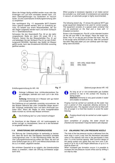
Das nachfolgend (Fig. 17) dargestellte WITT-Zubehör<br />
(kann optional bestellt werden) wird zur Entlüftung genutzt.<br />
Es besteht aus einem Wasserbehälter, der auf<br />
den <strong>Regler</strong> aufgesetzt werden kann <strong>und</strong> einem Schlauch<br />
mit ½“ Gewindeanschluss.<br />
Schrauben Sie den Gewindestift Pos. 93 an der dafür<br />
vorgesehenen Stelle ein (beim HS sowie HR 4 im<br />
Flansch). Setzen Sie den Wasserbehälter Pos. 91 auf<br />
<strong>und</strong> befestigen Sie den Schlauch Pos.9 2 an dem Entlüftungsventil<br />
EE3/EE6. Nachdem das Gefäß mit Wasser<br />
gefüllt wurde, kann das Einstellventil EE3/EE6 vorsichtig<br />
geöffnet werden.<br />
When purging is necessary regularly or air intake cannot<br />
be excluded, e.g. shaft seals of compressors are operating<br />
in vacuum, an automatic purger is highly recommended.<br />
The following sketch (fig. 17) shows the optional WITT gas<br />
purge equipment designed to be used for correct purging.<br />
The equipment consists of a special water container that<br />
can be positioned on the float and a hose with ½”<br />
threaded connection.<br />
Screw in the threaded pin, Pos.93, at the intended location<br />
(at the HS and HR4 in the flange). Place the water container,<br />
Pos. 91 on the pin and connect the hose, Pos. 92,<br />
to the purge valve EE3/EE6 at the top. After the container<br />
has been filled with water you can carefully open the regulating<br />
valve EE3/EE6.<br />
EE3<br />
EE6<br />
HR1-HR3, HS30-HS40<br />
HR4, HS50<br />
Entlüftungseinrichtung für HR / HS Fig. 17 Optional purge device HR / HS<br />
Solange Luftblasen bzw. nichtkondensierbare Gase<br />
aufsteigen, befindet sich noch Luft in der Anlage.<br />
Achtung: Ammoniak ist in Wasser sehr gut löslich<br />
<strong>und</strong> erzeugt keine Blasen.<br />
Die Entlüftung ist auf jedenfalls vorsichtig vorzunehmen, da<br />
das Wasser während des unter Umständen länger dauernden<br />
Vorgangs verdampfen kann <strong>und</strong> dann Ammoniak austreten<br />
kann. Wenn der <strong>Regler</strong> an einer frostgefährdeten<br />
Stelle montiert ist, könnte das Wasser einfrieren.<br />
Die Entlüftung darf nur unter Aufsicht erfolgen!<br />
Im Anschluss ist das Wasser z.B. mit Lackmuspapier zu<br />
prüfen <strong>und</strong> ggf. zu neutralisieren, bevor es in die Kanalisation<br />
eingeleitet werden darf<br />
As long as air or non-condensable gas bubbles<br />
continue to rise to the surface the housing is<br />
being purged.<br />
Attention:Ammonia is very good soluble in water<br />
and creates no bubbles.<br />
Purging must be carried out carefully as the water may<br />
over a period of time evaporate allowing ammonia to<br />
atmosphere also. The regulator should only be fitted with<br />
this air purger in a frost-free location to avoid the water<br />
freezing.<br />
Purging should only be carried out <strong>und</strong>er supervision!<br />
Upon completion of purging, the water should be<br />
checked and neutralized if required before safe disposal.<br />
11.6 ERWEITERUNG DER UNTERDRUCKDÜSE 11.6 ENLARGING THE LOW PRESSURE NOZZLE<br />
Die Bohrung der Unterdruckdüse ist werkseitig so bemessen,<br />
dass der durch den Gas-Bypass theoretisch ermittelte<br />
Leistungsverlust unter 1% der Nennleistung bleibt. Bei üblicher<br />
Leitungsdimensionierung sollten die Gase, die sich auf<br />
einer Entfernungen bis zu 30 m <strong>und</strong> Höhenunterschiede von<br />
bis zu 3 m bilden, abgeführt werden.<br />
Bei erhöhtem Gasanfall ist es möglich, die Unterdruckdüse<br />
etwas zu erweitern, indem die Öffnung schrittweise aufgebohrt<br />
wird.<br />
The hole of the low pressure nozzle is delivered from the<br />
work shop in such a way that the theoretical calculated<br />
value of the capacity loss due to the gas-bypass is less<br />
than 1% of the nominal capacity. With common design of<br />
the piping system any gases that may form over a distance<br />
of up to 30 m and height differences of up to 3 m<br />
shall be drawn off.<br />
When increased gas formation occurs it is possible to<br />
increase the low-pressure nozzle orifice size by drilling it<br />
out step by step.<br />
39