Hochdruckschwimmer- Regler Montage- und ... - KomMa
Hochdruckschwimmer- Regler Montage- und ... - KomMa
Hochdruckschwimmer- Regler Montage- und ... - KomMa

Sie wollen auch ein ePaper? Erhöhen Sie die Reichweite Ihrer Titel.
YUMPU macht aus Druck-PDFs automatisch weboptimierte ePaper, die Google liebt.
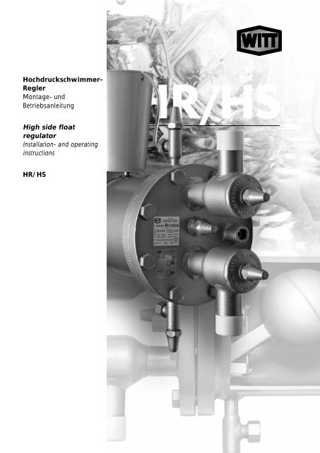
<strong>Hochdruckschwimmer</strong>-<br />
<strong>Regler</strong><br />
<strong>Montage</strong>- <strong>und</strong><br />
Betriebsanleitung<br />
High side float<br />
regulator<br />
Installation- and operating<br />
instructions<br />
HR/HS
MONTAGE- UND BETRIEBSANLEITUNG HR / HS OPERATION & SERVICE MANUAL<br />
INHALTSVERZEICHNIS<br />
CONTENTS<br />
1. EINLEITUNG............................................................................ 4<br />
1.1 VERWENDUNGSZWECK.............................................. 4<br />
1.2 SICHERHEITSBESTIMMUNGEN .................................. 4<br />
1.3 HAFTUNGSAUSSCHLUß.............................................. 4<br />
2. GEWÄHRLEISTUNGSBESTIMMUNGEN ................................ 5<br />
1. INTRODUCION .........................................................................4<br />
1.1 INTENDED USE .............................................................4<br />
1.2 SAFETY REQUIREMENTS.............................................4<br />
1.3 MANUFACTURER DISCLAIMER....................................4<br />
2. TERMS OF WARRENTY...........................................................5<br />
3. TECHNISCHE INFORMATION................................................. 5<br />
3.1 TYPENBEZEICHNUNG ................................................. 5<br />
3.2 LIEFERUMFANG........................................................... 6<br />
3.3 ABNAHMEN/BESCHEINIGUNGEN ............................... 7<br />
3.4 BESTELLANGABEN...................................................... 7<br />
3.5 STEUEREINHEIT .......................................................... 9<br />
4. TECHNISCHE DATEN ............................................................10<br />
4.1 MATERIALIEN ..............................................................10<br />
4.2 DRUCK/TEMPERATUR BEREICHE.............................10<br />
4.3 ÜBERBLICK..................................................................11<br />
4.4 ABMESSUNGEN ..........................................................16<br />
4.5 GEÄNDERTE VENTILSTELLUNGEN...........................21<br />
5. FUNKTIONSBESCHREIBUNG ...............................................23<br />
5.1 FUNKTION INNERHALB DER ANLAGE.......................23<br />
5.2 SCHWIMMER-REGELUNG ..........................................26<br />
5.3 FUNKTION DER UNTERDRUCKDÜSE........................26<br />
6. PLANUNGSHINWEISE ...........................................................29<br />
6.1 ALLGEMEINES.............................................................29<br />
6.2 AUSWAHLKRITERIEN .................................................29<br />
6.3 ANORDNUNG...............................................................29<br />
6.4 ZULAUFLEITUNG.........................................................32<br />
6.5 EINSPRITZLEITUNG....................................................33<br />
7. TRANSPORT UND LAGERUNG.............................................34<br />
3. TECHNICAL INFORMATION....................................................5<br />
3.1 DESCRIPTION OF TYPES: ............................................5<br />
3.2 SCOPE OF DELIVERY...................................................6<br />
3.3 INSPECTIONS/CERTIFICATES .....................................7<br />
3.4 ORDERINFORMATION ..................................................7<br />
3.5 CONTROL UNIT .............................................................9<br />
4. TECHNICAL DATA .................................................................10<br />
4.1 MATERIALS..................................................................10<br />
4.2 PRESSURE/TEMPERATURE RANGE .........................10<br />
4.3 OVERVIEW...................................................................11<br />
4.4 DIMENSIONS ...............................................................16<br />
4.5 MODIFIED VALVE POSITIONS....................................21<br />
5. DESCRIPTION OF OPERATION ............................................23<br />
5.1 OPERATION WITHIN THE PLANT...............................23<br />
5.2 FLOAT REGULATION ..................................................26<br />
5.3 FUNCTION OF THE LOW PRESSURE NOZZLE .........26<br />
6. HINTS FOR PLANNING..........................................................29<br />
6.1 GENERAL.....................................................................29<br />
6.2 SELECTION CRITERIA ................................................29<br />
6.3 LOCATION ...................................................................29<br />
6.4 LIQUID FEED LINE.......................................................32<br />
6.5 LOW PRESSURE LINE FROM THE REGULATOR ......33<br />
7. TRANSPORT AND STORAGE ...............................................34<br />
8. MONTAGE .............................................................................34<br />
8.1 MONTAGEVORBEREITUNG........................................34<br />
8.2 MONTAGEANLEITUNG................................................35<br />
9. INBETRIEBNAHME ................................................................35<br />
9.1 VORBEREITUNG DER INBETRIEBNAHME.................35<br />
9.2 INBETRIEBNAHME ......................................................35<br />
10. BETRIEB.................................................................................36<br />
8. INSTALLATION .....................................................................34<br />
8.1 PREPARING FOR INSTALLATION ..............................34<br />
8.2 FIXING INSTRUCTIONS ..............................................35<br />
9. COMMISSIONING...................................................................35<br />
9.1 PRIOR TO COMMISSIONING ......................................35<br />
9.2 COMMISSIONING ........................................................35<br />
10. OPERATION ...........................................................................36<br />
11. WARTUNG UND INSTANDHALTUNG....................................36<br />
11.1 FUNKTIONSKONTROLLE.......................................36<br />
11.2 AUSTAUSCH DES SCHWIMMKÖRPERS...............36<br />
11.3 AUSTAUSCH DER HEBELPACKUNG ....................38<br />
11.4 AUSTAUSCH DER VENTILPACKUNG....................38<br />
11.5 ENTLÜFTUNG.........................................................38<br />
11.6 ERWEITERUNG DER UNTERDRUCKDÜSE ..........39<br />
12. FEHLERSUCHE......................................................................40<br />
12.1 LUFT IN DER KÄLTEANLAGE ................................40<br />
12.2 GASBILDUNG IN DER ZULAUFLEITUNG...............40<br />
12.3 PARALLELSCHALTUNG VON VERFLÜSSIGERN..41<br />
12.4 LUFTGEKÜHLTE VERFLÜSSIGER.........................41<br />
12.5 PLATTENVERFLÜSSIGER .....................................41<br />
12.6 HD-SAMMELBEHÄLTER.........................................41<br />
12.7 EINSATZ VON ÖLKÜHLERN ..................................41<br />
11. SERVICE AND MAINTANANCE .............................................36<br />
11.1 FUNCTIONING CHECK...........................................36<br />
11.2 REPLACING THE FLOAT BALL..............................36<br />
11.3 REPLACING THE LEVER PACKING.......................38<br />
11.4 REPLACEMENT OF THE VALVE PACKING...........38<br />
11.5 PURGING................................................................38<br />
11.6 ENLARGING THE LOW PRESSURE NOZZLE .......39<br />
12. TROUBLE SHOOTING ...........................................................40<br />
12.1 AIR IN THE REGRIGERATION SYSTEM................40<br />
12.2 GAS FORMATION IN THE LIQUID FEED LINE ......40<br />
12.3 PARALLEL OPERATION OF CONDENSERS .........41<br />
12.4 AIRCOOLED CONDENSER ....................................41<br />
12.5 PLATE TYPE CONDENSER....................................41<br />
12.6 USE OF HP LIQIUD RECEIVERS ...........................41<br />
12.7 USE OF OIL COOLERS ..........................................41<br />
Th. Witt Kältemaschinenfabrik GmbH<br />
Lukasstrasse 32, D-52070 Aachen<br />
Tel. +49-241-18208-0, Fax. +49-241-18208-49<br />
http://www.TH-WITT.com, Info@TH-WITT.com<br />
W3510-6.01d – 03/2007<br />
3
<strong>Hochdruckschwimmer</strong>-<strong>Regler</strong><br />
High Pressure Float Regulator<br />
HR/HS<br />
<strong>Montage</strong>- <strong>und</strong> Betriebsanleitung 97/23/EG Installation- and operating instructions<br />
1. EINLEITUNG 1. INTRODUCION<br />
Bitte lesen Sie die komplette Betriebsanleitung sorgfältig,<br />
bevor Sie den <strong>Hochdruckschwimmer</strong>-<strong>Regler</strong> auswählen,<br />
in Gebrauch nehmen oder Wartungsarbeiten durchführen.<br />
Please read the entire manual careful before selecting,<br />
installing, commissioning or servicing the highpressure<br />
float regulators.<br />
1.1 VERWENDUNGSZWECK 1.1 INTENDED USE<br />
Der WITT <strong>Hochdruckschwimmer</strong>-<strong>Regler</strong> darf ausschließlich in<br />
Kälteanlagen eingesetzt werden, um verflüssigtes Kältemittel<br />
von der Hochdruckseite auf die Niederdruckseite zu entspannen.<br />
The WITT high-pressure float regulator is intended for<br />
the use in refrigerant plants to expand liquid refrigerant<br />
from the high pressure to the low-pressure side.<br />
1.2 SICHERHEITSBESTIMMUNGEN 1.2 SAFETY REQUIREMENTS<br />
Sämtliche beschriebene Arbeiten an dem <strong>Hochdruckschwimmer</strong>-<strong>Regler</strong><br />
dürfen nur von sachk<strong>und</strong>igem,<br />
im Umgang mit Kälteanlagen geschultem Personal<br />
durchgeführt werden, das die einschlägigen<br />
Vorschriften zur Erstellung <strong>und</strong> Wartung von Kälteanlagen<br />
kennt. Auch die Sicherheitsvorschriften hinsichtlich<br />
des Umgangs mit Kältemittel sind zu beachten,<br />
insbesondere das Tragen der persönlichen<br />
Schutzbekleidung <strong>und</strong> einer Schutzbrille.<br />
Die auf dem Typenschild <strong>und</strong> den Zeichnungen angegebenen<br />
Temperatur- <strong>und</strong> Druckangaben dürfen<br />
auf keinen Fall überschritten werden.<br />
Any of the following specified procedures must<br />
be carried out by trained and knowledgeable<br />
personnel experienced in installation and service<br />
of refrigerant plants. All personnel must be<br />
familiar with the National legal requirements<br />
and safety regulations. All safety regulations<br />
and codes of practice concerning the use of<br />
refrigerants must be adhered to, with special<br />
attention paid to protection clothing and wearing<br />
of safety glasses.<br />
Under no circumstances are the stated design<br />
temperature- and pressure limitations on the<br />
data plate to be exceeded!<br />
Wenn am Eintritts- <strong>und</strong> am Austrittsstutzen Absperrventile<br />
vorgesehen sind, so muss sichergestellt werden,<br />
dass die Ventile im Betrieb immer voll geöffnet<br />
bleiben.<br />
Achtung! Dem Inhalt dieser Betriebsanleitung ist<br />
unbedingt Folge zu leisten! Abweichender Einsatz<br />
schließt eine Haftung <strong>und</strong> Gewährleistung durch den<br />
Hersteller aus!<br />
Die örtlichen Vorschriften für Kälteanlagen <strong>und</strong> Umweltauflagen,<br />
insbesondere bei der Kältemittel- <strong>und</strong><br />
Kälteölentsorgung sind einzuhalten.<br />
.<br />
When installing inlet and outlet valves please<br />
ensure that the valves are fully open during<br />
operation.<br />
Important! The contents of this manual must<br />
be adhered to. Deviation from the specified<br />
conditions will make any claim for liability or<br />
warranty void.<br />
All local rules for operation of refrigeration systems<br />
and ecological requirements, especially<br />
waste treatment of refrigerants and oils must be<br />
complied with.<br />
1.3 HAFTUNGSAUSSCHLUß 1.3 MANUFACTURER DISCLAIMER<br />
Auch bei bestimmungsgemäßer Verwendung können Gefahren<br />
für Leib <strong>und</strong> Leben des Benutzers oder Dritter bzw. Beeinträchtigungen<br />
der Maschine <strong>und</strong> anderer Sachwerte entstehen.<br />
Even when the float regulator is used for the specified<br />
intended purpose it cannot be totally excluded some<br />
danger for the life of the user may exist in the installation<br />
or system.<br />
Übersetzungen werden nach bestem Wissen durchgeführt.<br />
Eine irgendwie geartete Haftung für Übersetzungsfehler können<br />
wir nicht übernehmen.<br />
Gegenüber Darstellungen <strong>und</strong> Angaben dieser Betriebsanleitung<br />
sind technische Änderungen, die zur Verbesserung des<br />
<strong>Hochdruckschwimmer</strong>-<strong>Regler</strong>s notwendig werden, vorbehalten.<br />
Translations are carried out to the best of our knowledge.<br />
We are unable to accept any liability for translation<br />
errors.<br />
We reserve the right to change descriptions, graphs or<br />
other statements, which are required due to technical<br />
development of the high-pressure float regulators.<br />
4
2. GEWÄHRLEISTUNGSBESTIMMUNGEN 2. TERMS OF WARRENTY<br />
Zur Vermeidung von Unfällen dürfen an den <strong>Hochdruckschwimmer</strong>-<strong>Regler</strong>n<br />
weder Veränderungen noch Umbauten<br />
vorgenommen werden, die durch die TH. WITT KÄLTEMA-<br />
SCHINENFABRIK GMBH nicht ausdrücklich schriftlich genehmigt<br />
worden sind.<br />
Diese Betriebsanleitung enthält die international genormten<br />
SI-Maßeinheiten.<br />
Alle Angaben <strong>und</strong> Hinweise für die Bedienung <strong>und</strong> Instandhaltung<br />
dieser <strong>Hochdruckschwimmer</strong>-<strong>Regler</strong> erfolgen unter Berücksichtigung<br />
unserer bisherigen Erfahrungen <strong>und</strong> Erkenntnissen<br />
nach bestem Wissen.<br />
Eine Haftung oder Gewährleistung ist ausgeschlossen,<br />
wenn:<br />
• die Hinweise <strong>und</strong> Anweisungen der Betriebsanleitung nicht<br />
beachtet werden,<br />
• die <strong>Hochdruckschwimmer</strong>-<strong>Regler</strong> einschließlich zugehöriger<br />
Einrichtungen fehlerhaft bedient werden bzw. deren Handhabung<br />
nicht dem vorgeschriebenen Ablauf entspricht,<br />
• die <strong>Hochdruckschwimmer</strong>-<strong>Regler</strong> entgegen ihrer Bestimmung<br />
zweckentfremdet genutzt werden,<br />
• Schutzeinrichtungen nicht benutzt oder außer Funktion<br />
gesetzt werden,<br />
• Funktionsänderungen jeder Art ohne unsere schriftliche<br />
Zustimmung durchgeführt werden,<br />
• die einschlägigen Sicherheitsbestimmungen nicht beachtet<br />
werden,<br />
• die <strong>Hochdruckschwimmer</strong>-<strong>Regler</strong> unsachgemäß (zeitlich wie<br />
auch in der Ausführung) gewartet werden.<br />
• beim Austausch von Teilen bzw. für die Ersatzteilbeschaffung<br />
nicht die vom Hersteller freigegebenen Originalersatzteile<br />
verwendet werden.<br />
In order to avoid accidents and ensure optimum performance,<br />
no modifications or conversions may be<br />
carried out to the high-pressure float regulator without<br />
the explicit written approval by TH.WITT KÄLTE-<br />
MASCHINENFABRIK GMBH.<br />
These instructions are based on internationally standardised<br />
SI units of measurements.<br />
All data and information on the operation and maintenance<br />
of the float regulators are provided based on our<br />
extensive experience and to the best of our technical<br />
knowledge.<br />
Our liability or warranty is excluded, if:<br />
• The information and instructions in the operating<br />
manual are ignored,<br />
• The high-pressure float regulators including accessories<br />
are operated incorrectly or are not installed according<br />
to the instructions.<br />
• The high-pressure float regulators are used for purpose<br />
other than that for which it was designed.<br />
• Safety devices fitted are not used or disconnected<br />
• There have been modifications made to the high<br />
pressure float regulator without the manufacturers<br />
written approval<br />
• The safety regulations are not adhered to<br />
• The high-pressure float regulators have not been<br />
maintained or repaired properly (regarding timing and<br />
execution)<br />
• Parts that are used during maintenance or service<br />
are not the approved genuine TH. WITT spare parts.<br />
3. TECHNISCHE INFORMATION 3. TECHNICAL INFORMATION<br />
3.1 TYPENBEZEICHNUNG 3.1 DESCRIPTION OF TYPES:<br />
Es sind vier Baugrößen der Standard-<strong>Hochdruckschwimmer</strong>-<br />
HR1 bis HR4 lieferbar. Außerdem bieten wir modular aufgebaute<br />
<strong>Regler</strong> vom Typ HS30 bis HS50, WPHR Schwimmer für<br />
Wärmepumpen-Anwendungen sowie HR1BW zur Kondensatableitung<br />
an.<br />
Die Gehäuse können jeweils mit verschiedenen Schwimmerkugeln<br />
ausgerüstet werden. Es werden N-Kugeln <strong>und</strong> R-<br />
Kugeln für unterschiedliche Kältemittel angeboten.<br />
Die Ausführungen -H, -M, -L unterscheiden sich bzgl. Austrittsgeometrien<br />
bzw. Hebelübersetzungen.<br />
HR-<strong>Regler</strong> kommen für Ammoniak-Anwendungen bis ca.<br />
35°C Kondensationstemperatur <strong>und</strong> bei HFCKWs über den<br />
gesamten Temperaurbereich zum Einsatz.<br />
HS <strong>Regler</strong> ermöglichen bei kleiner Baugröße größere Leistungen.<br />
Auch bei geringer Dichte des Kältemittels (z.B. Ammoniak<br />
bei Kondensationstemperaturen > 35°C) sowie bei<br />
CO2-Anwendungen bis 40 bar sind HS-<strong>Regler</strong> die richtige<br />
Wahl.<br />
WPHR-<strong>Regler</strong> wurden für den Einsatz in NH 3 Wärmepumpen<br />
konstruiert. Sie sind für PS 40 ausgelegt <strong>und</strong> enthalten einen<br />
druckentlastete Auftrniebskörper.<br />
Der HR1BW wurde speziell für die Kondensatableitung bei<br />
Heißgasabtauung entwickelt. Aber auch zur Ableitung von<br />
Flüssigkeit aus einem Enthitzer, sowie in Kombination mit<br />
einem Ölabscheider zur Ölrückführung, hat sich dieser Typ<br />
bewährt.<br />
There are four sizes of standard float regulators available:<br />
HR1 to HR4. Furthermore we offer modular<br />
designed regulators HS30 to HS50, WPHR types for<br />
heat-pump applications and a HR1BW for condensate<br />
draining.<br />
The float regulator housing may be equipped with<br />
different types of float balls. There are type N- and R-<br />
ball floats available for different refrigerants.<br />
Executions –H, -M, -L have different liquid orifice outlet<br />
dimensions respective varying lever transmissions.<br />
HR-regulators are used for ammonia systems up to<br />
condensing temperatures of about 35°C and HFCs<br />
over the entire temperature range.<br />
HS-regutaors offer larger capacities at a reduced size<br />
of the housing. Also at low densities (e.g. ammonia at<br />
condensing temperatures > 35°C) or CO2 applications<br />
up to 40 bar, HS types are the right choice.<br />
WPHR- types were designed for the use with NH 3 heat<br />
pumps. They are rated for PS 40 and include a pressure-released<br />
float.<br />
The type HR1 BW is especially designed for the condensate<br />
drainage at hot gas defrost in systems with<br />
long hot gas lines. They are also favourable to work in<br />
conjunction with desuperheaters or in combination with<br />
an oil separator as an oil return.<br />
5
Fig.1a HR 1 – 3 Fig. 1b HR 4<br />
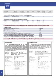
3.2 LIEFERUMFANG 3.2 SCOPE OF DELIVERY<br />
STANDARD LIEFERUMFANG HR<br />
Absperrventile am Eintritt- <strong>und</strong> Austrittsstutzen bzw.<br />
ASTM-Stutzen Schedule40 (bitte angeben)<br />
Oben angebrachtes Regelventil zum Entlüften (EE3 bzw.<br />
EE6 bei HR4)<br />
Unten angebautes Entleerungsventil EA10 GB<br />
Nocken G ½” / G ¼” kombiniert für Anschluss eines Sicherheitsventils<br />
(ab HR2)<br />
Integrierte Unterdruckdüse<br />
Blindkappe am Hebelaustritt<br />
Rahmen, nur für den HR4<br />
OPTIONALER LIEFERUMFANG HR<br />
Befestigungskonsolen (lose beigepackt)<br />
abweichende Ventilstellung (siehe Kap. 4.5)<br />
Unterdruckdüse verschlossen<br />
Entlüftungseinrichtung (aufsetzbares Wassergefäß mit<br />
Schlauchverbindung zum Entlüftungsventil)<br />
Einzelabnahme durch TÜV / andere Prüfgesellschaften<br />
Sonderausführungen auf Anfrage<br />
STANDARD SCOPE OF DELIVERY HR<br />
Stop valves at inlet and outlet respective ASTM connections<br />
schedule 40 (please specify)<br />
Top mounted regulating valve for purging (EE3 resp.<br />
EE6 for HR4)<br />
Bottom mounted drainage valve EA10GB<br />
Combined G ½” / G ¼” threaded connection for safety<br />
valve (larger than HR2)<br />
Integrated low pressure nozzle<br />
Cap for hand lever control<br />
mounting frame, only for HR4<br />
OPTIONAL SCOPE OF DELIVERY HR<br />
Support brackets or mounting frame (supplied loose)<br />
Alternative valve connection positions (see chapter 4.5)<br />
Closed low pressure nozzle<br />
Gas purge kit (special water container with hose and<br />
connection to the purge valve)<br />
Individual inspections of TÜV or other institutions<br />
Special non standard executions upon request<br />
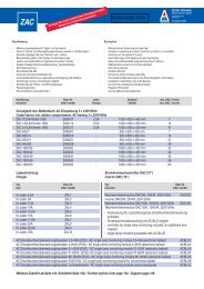
Fig 1c HS30 – HS40<br />
STANDARD LIEFERUMFANG HS<br />
DIN- oder ASTM (Schedule 40) Eintrittsstutzen (bitte angeben)<br />
Absperrventil oder ASTM-Stutzen am Austritt (bitte unbedingt<br />
angeben)<br />
Verlängertes Einstellventil EE6 zum Entlüften, oben am<br />
Deckel montiert<br />
Verlängertes Absperrventil EA10GB zum Entleeren, unten<br />
am Deckel montiert<br />
Blindkappe am Hebelaustritt<br />
Rahmen, nur für HS50<br />
Fig. 1d HS50<br />
STANDARD SCOPE OF DELIVERY HS<br />
DIN-or ASTM (Schedule 40) inlet connection (please<br />
specify)<br />
Stop valve or ASTM connection at the outlet (please<br />
specify)<br />
Extended purge valve EE6, top mounted in the cover<br />
plate<br />
Extended stop valve EA10 GB for drainage, bottom<br />
mounted in the cover plate<br />
Cap for hand lever control<br />
Mounting frame, only for HS50<br />
6
OPTIONALER LIEFERUMFANG HS<br />
Unterdruckdüse<br />
Entlüftungseinrichtung (aufsetzbares Wassergefäß mit<br />
Schlauchverbindung zum Entlüftungsventil)<br />
Einzelabnahme durch TÜV bzw. durch andere Prüfgesellschaften<br />
OPTIONAL SCOPE OF DELIVERY HS<br />
Low pressure nozzle for HS types<br />
Gas purge kit (special water container with hose and<br />
connection to the purge valve)<br />
Individual inspections of TÜV or other institutions<br />
Fig. 1e WP2HR / WP3HR<br />
STANDARD LIEFERUMFANG WPHR<br />
DIN Eintritts- <strong>und</strong> Austrittsstutzen<br />
Oben angebrachtes Regelventil EE3 zum Entlüften<br />
Unten angebautes Entleerungsventil EA10 GB<br />
Nocken G ½” / G ¼” kombiniert für Anschluss eines Sicherheitsventils<br />
Integrierte Unterdruckdüse<br />
Blindkappe am Hebelaustritt<br />
STANDARD SCOPE OF DELIVERY WPHR<br />
DIN inlet and outlet connection<br />
Top mounted regulating valve EE3 for purging<br />
Bottom mounted drainage valve EA10GB<br />
Combined G ½” / G ¼” threaded connection for safety<br />
valve<br />
Integrated low pressure nozzle<br />
Cap for hand lever control<br />
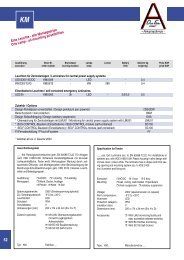
STANDARD LIEFERUMFANG HR1BW<br />
DIN Eintrittsstuten<br />
Absperrventil EA10 am Austritt<br />
Blindkappe am Hebelaustritt<br />
Fig. 1f HR1BW<br />
STANDARD SCOPE OF DELIVERY HR1BW<br />
DIN inlet connection<br />
Stop valve EA10 at the outlet<br />
Cap for hand lever control<br />
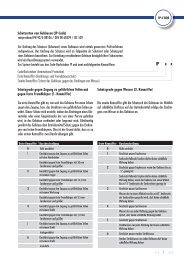
3.3 ABNAHMEN/BESCHEINIGUNGEN 3.3 INSPECTIONS/CERTIFICATES<br />
<strong>Hochdruckschwimmer</strong> <strong>Regler</strong> werden als druckhaltende<br />
Ausrüstungsteile ausgelegt, gefertigt <strong>und</strong> mit einer CE-<br />
Kennzeichnung gemäß Druckgeräterichtlinie ausgeliefert.<br />
Als Gr<strong>und</strong>lage dient das AD-Regelwerk, sowie aktuelle<br />
Werkstoffnormen.<br />
Außerdem können die <strong>Regler</strong> mit einer GOST Kennzeichnung<br />
bestellt werden.<br />
Eine Bescheinigung, dass die ATEX-Richtlinie nicht auf<br />
<strong>Hochdruckschwimmer</strong>-<strong>Regler</strong> anwendbar ist, wurde auf<br />
Gr<strong>und</strong>lage der Zündgefahrenbewertung erstellt <strong>und</strong> ist auf<br />
Anfrage erhältlich.<br />
High side float regulators are designed and manufactured<br />
as pressure resistant equipment and will be supplied<br />
with CE mark according to PED.<br />
The evaluation is based on the AD regulation and actual<br />
material standards.<br />
The regulators can also be ordered with GOST mark.<br />
A certificate, stating that the ATEX regulation does not<br />
apply to high side float regulators, is available upon<br />
request. It was based a risk assessment considering<br />
potential ignition sources .<br />
3.4 BESTELLANGABEN 3.4 ORDERINFORMATION<br />
7
Zur richtigen Auswahl Ihres <strong>Hochdruckschwimmer</strong>-<br />
<strong>Regler</strong>s benötigen wir folgende Angaben:<br />
• Kältemittel<br />
• Kondensationstemperatur ....[ °C oder °F]<br />
• Verdampfungstemperatur .....[°C oder °F]<br />
• Kälte-/Wärmepumpenleistung ... [kW]<br />
In order to select the correct high side float regulator for<br />
your application we will need the following information<br />
• Refrigerant<br />
• Condensing temperature …. [°C or °F]<br />
• Evaporating temperature....[°C or °F]<br />
• Capacity … [KW]<br />
Haben Sie bereits einen <strong>Hochdruckschwimmer</strong>-<strong>Regler</strong><br />
ausgewählt, geben Sie bitte folgende Daten an:<br />
• Baugröße: HR 1 bis HR 4, bzw. HS30 bis HS50<br />
• Kältemittel: N- oder R- Kugel bzw bei HS auch SK Kugel<br />
• Ausführung: -L, -M, -H<br />
• Mit / ohne Unterdruckdüse bei HS-<strong>Regler</strong>n<br />
• Erforderliche Abnahmen/Dokumentation<br />
• Falls gewünscht geänderte Ventilstellung gemäß Kapitel<br />
4.6<br />
• Sonderausführungen<br />
Bestelltext<br />
z.B. HR3-H mit N-Kugel oder<br />
bei HS <strong>Regler</strong>n steht die erste Zahl für die Baugröße <strong>und</strong><br />
die zweite Zahl bedeutet:<br />
1 N-Kugel ohne Unterdruckdüse<br />
2 spezielle SK-Kugel ohne Unterdruckdüse<br />
3 R-Kugel ohne Unterdruckdüse<br />
4 N-Kugel mit Unterdruckdüse<br />
5 spezielle SK-Kugel mit Unterdruckdüse<br />
6 R-Kugel mit Unterdruckdüse<br />
z.B. HS34-M (HS-<strong>Regler</strong> mit N-Kugel, mit Unterdruckdüse<br />
<strong>und</strong> in M-Ausführung)<br />
Please always specify the following technical information<br />
when ordering a float regulator:<br />
• Size: HR 1 to HR 4, resp. HS30 to HS50<br />
• Refrigerant: N- or R-ball, resp. for HS also SK-ball<br />
• Execution: –L, -M, -H<br />
• With or without low pressure nozzle for HS-regulators<br />
• Required standard of inspection and certification<br />
documentation.<br />
• If required alternative valve position, see chapter 4.6<br />
• Any special non standard requirements<br />
Order text<br />
e.g. HR3 with N-float ball or<br />
for HS-regulators the first number indicates the size,<br />
wheras the second number has the following meaning:<br />
1 N-float ball, without low pressure nozzle<br />
2 special SK- ball, without low pressure nozzle<br />
3 R- float ball, without low pressure nozzle<br />
4 N-Kugel float ball, with low pressure nozzle<br />
5 special SK- ball, with low pressure nozzle<br />
6 R- float ball, with low pressure nozzle<br />
e.g. HS34-M (HS-regulator with N-float ball, with low<br />
pressure nozzle and M-execution)<br />
Ersatzteilbestellungen<br />
Die Schiebersteuerung betreffende Ersatzteile können nur<br />
als gesamte Steuereinheit geliefert werden, da eine Justierung<br />
der Teile erforderlich ist.<br />
Bitte geben Sie Typ, Kältemittel <strong>und</strong> Baujahr an, wenn<br />
Sie eine Steuereinheit bestellen:<br />
z.B. HR3 – M, NH 3, 05/96<br />
Ordering replacement parts<br />
Replacements parts for the slide valve control are only<br />
available as a complete control unit, including the ball<br />
float, because all parts need to be adjusted.<br />
Please indicate type, refrigerant and year when ordering<br />
a control unit:<br />
e.g. HR3 – M, NH 3, 05/96<br />
8
3.5 STEUEREINHEIT 3.5 CONTROL UNIT<br />
Artikel-Nr.<br />
Article No.<br />
3591.000232<br />
3591.000233<br />
3591.000234<br />
3591.000235<br />
3591.000236<br />
3591.000237<br />
3591.000238<br />
3591.000239<br />
3591.000240<br />
3591.000245<br />
3591.000246<br />
3591.000242<br />
3591.000243<br />
3591.000247<br />
3591.000248<br />
3591.000249<br />
3591.000254<br />
3591.000255<br />
3591.000251<br />
3591.000252<br />
3591.000256<br />
3591.000257<br />
3591.000258<br />
Typ<br />
Model<br />
HR1-L<br />
HR1-M<br />
HR1-H<br />
HR1-L<br />
HR1-M<br />
HR1-H<br />
HR2-L<br />
HR2-M<br />
HR2-H<br />
HR2 SK-M<br />
HR2 SK-H<br />
HR2-M<br />
HR2-H<br />
HR3-L<br />
HR3-M<br />
HR3-H<br />
HR3 SK-M<br />
HR3 SK-H<br />
HR3-M<br />
HR3-H<br />
HR4-L<br />
HR4-M<br />
HR4-H<br />
Kugel-Art<br />
Ball-type<br />
1)<br />
N<br />
N<br />
N<br />
R<br />
R<br />
R<br />
N<br />
N<br />
N<br />
SK<br />
SK<br />
R<br />
R<br />
N<br />
N<br />
N<br />
SK<br />
SK<br />
R<br />
R<br />
N<br />
N<br />
N<br />
Drossel<br />
Orifice<br />
Unterdruckdüse ø<br />
Low-press. nozzle ø<br />
Kugel ø<br />
Ball ø<br />
Länge Hebel<br />
Length Lever<br />
Gewicht Steuereinheit<br />
Weight Control Unit<br />
[mm²] [mm] [mm] ~ [mm] ~ [kg]<br />
5<br />
3<br />
2<br />
11<br />
6<br />
4<br />
56<br />
37<br />
19<br />
30<br />
19<br />
56<br />
37<br />
159<br />
108<br />
69<br />
85<br />
69<br />
159<br />
108<br />
333<br />
236<br />
154<br />
3591.000262 HR4 SK-H - 146 4,0 230 300 2,5<br />
3591.000259<br />
3591.000260<br />
3591.000261<br />
HR4-L<br />
HR4-M<br />
HR4-H<br />
R<br />
R<br />
R<br />
470<br />
333<br />
236<br />
0,7<br />
0,7<br />
0,7<br />
0,7<br />
0,7<br />
0,7<br />
1,5<br />
1,5<br />
1,0<br />
2,0<br />
1,5<br />
1,5<br />
1,0<br />
3,0<br />
3,0<br />
2,0<br />
3,0<br />
2,0<br />
3,0<br />
2,0<br />
6,0<br />
6,0<br />
4,0<br />
6,0<br />
6,0<br />
4,0<br />
100<br />
100<br />
100<br />
100<br />
100<br />
100<br />
120<br />
120<br />
120<br />
150<br />
150<br />
120<br />
120<br />
150<br />
150<br />
150<br />
200<br />
200<br />
150<br />
150<br />
200<br />
200<br />
200<br />
150<br />
150<br />
150<br />
87<br />
87<br />
87<br />
48<br />
87<br />
87<br />
95<br />
87<br />
87<br />
87<br />
87<br />
95<br />
87<br />
148<br />
133<br />
133<br />
133<br />
133<br />
148<br />
133<br />
300<br />
300<br />
300<br />
300<br />
300<br />
300<br />
0,31<br />
0,31<br />
0,31<br />
0,49<br />
0,51<br />
0,51<br />
0,44<br />
0,44<br />
0,44<br />
0,70<br />
0,70<br />
0,65<br />
0,65<br />
0,90<br />
0,90<br />
0,90<br />
1,75<br />
1,75<br />
1,2<br />
1,2<br />
2,65<br />
2,65<br />
2,65<br />
3,36<br />
3,36<br />
3,36<br />
Artikel-Nr.<br />
Article No.<br />
3591.000238<br />
3591.000239<br />
3591.000240<br />
3591.000263<br />
3591.000245<br />
3591.000246<br />
3591.000242<br />
3591.000243<br />
3591.000247<br />
3591.000248<br />
3591.000249<br />
3591.000264<br />
3591.000254<br />
3591.000255<br />
3591.000251<br />
3591.000252<br />
3591.000256<br />
3591.000257<br />
3591.000258<br />
3591.000259<br />
3591.000260<br />
3591.000261<br />
Typ<br />
Model<br />
HS31/34-L<br />
HS31/34-M<br />
HS31/34-H<br />
HS32/35-L<br />
HS32/35-M<br />
HS32/35-H<br />
HS33/36-M<br />
HS33/36-H<br />
HS41/44-L<br />
HS41/44-M<br />
HS41/44-H<br />
HS42/45-L<br />
HS42/45-M<br />
HS42/45-H<br />
HS43/46-M<br />
HS43/46-H<br />
HS51/54-L<br />
HS51/54-M<br />
HS51/54-H<br />
HS53/56-L<br />
HS53/56-M<br />
HS53/56-H<br />
Kugel-Art<br />
Ball-type<br />
1)<br />
N<br />
N<br />
N<br />
SK<br />
SK<br />
SK<br />
R<br />
R<br />
N<br />
N<br />
N<br />
SK<br />
SK<br />
SK<br />
R<br />
R<br />
N<br />
N<br />
N<br />
R<br />
R<br />
R<br />
Drossel<br />
Orifice<br />
Unterdruckdüse ø<br />
Low-press. nozzle ø<br />
Kugel ø<br />
Ball ø<br />
Länge Hebel<br />
Length Lever<br />
Gewicht Steuereinheit<br />
Weight Control Unit<br />
[mm²] [mm] [mm] ~ [mm] ~ [kg]<br />
56<br />
37<br />
19<br />
52<br />
30<br />
19<br />
56<br />
37<br />
159<br />
108<br />
69<br />
140<br />
85<br />
69<br />
159<br />
108<br />
333<br />
236<br />
154<br />
470<br />
333<br />
236<br />
ohne / optional<br />
without / optional<br />
ohne / optional<br />
without / optional<br />
ohne / optional<br />
without / optional<br />
ohne / optional<br />
without / optional<br />
ohne / optional<br />
without / optional<br />
ohne / optional<br />
without / optional<br />
ohne / optional<br />
without / optional<br />
ohne / optional<br />
without / optional<br />
120<br />
120<br />
120<br />
150<br />
150<br />
150<br />
120<br />
120<br />
150<br />
150<br />
150<br />
200<br />
200<br />
200<br />
150<br />
150<br />
200<br />
200<br />
200<br />
200<br />
200<br />
200<br />
95<br />
87<br />
87<br />
87<br />
87<br />
87<br />
95<br />
87<br />
148<br />
133<br />
133<br />
133<br />
133<br />
133<br />
148<br />
133<br />
300<br />
300<br />
300<br />
300<br />
300<br />
300<br />
0,44<br />
0,44<br />
0,44<br />
0,70<br />
0,70<br />
0,70<br />
0,65<br />
0,65<br />
0,90<br />
0,90<br />
0,90<br />
1,75<br />
1,75<br />
1,75<br />
1,2<br />
1,2<br />
2,65<br />
2,65<br />
2,65<br />
3,36<br />
3,36<br />
3,36<br />
9
Artikel-Nr.<br />
Article No.<br />
Typ<br />
Model<br />
Kugel-Art<br />
Ball-type<br />
1)<br />
Drossel<br />
Orifice<br />
Unterdruckdüse ø<br />
Low-press. nozzle ø<br />
Kugel ø<br />
Ball ø<br />
Länge Hebel<br />
Length Lever<br />
Gewicht Steuereinheit<br />
Weight Control Unit<br />
[mm²] [mm] [mm] ~ [mm] ~ [kg]<br />
3591.000244<br />
3591.000253<br />
WP2 Hr<br />
WP3 Hr<br />
WP<br />
WP<br />
11<br />
46<br />
1,8<br />
3,0<br />
150<br />
200<br />
87<br />
133<br />
0,38<br />
1,01<br />
3591.000232<br />
3591.000233<br />
3591.000234<br />
HR1 BW-L<br />
HR1 BW-M<br />
HR1 BW-H<br />
N<br />
N<br />
N<br />
5<br />
3<br />
2<br />
-<br />
-<br />
-<br />
100<br />
100<br />
100<br />
87<br />
87<br />
87<br />
0,31<br />
0,31<br />
0,31<br />
3591.000235<br />
3591.000236<br />
3591.000237<br />
HR1 BW-L<br />
HR1 BW-M<br />
HR1 BW-H<br />
R<br />
R<br />
R<br />
11<br />
6<br />
4<br />
-<br />
-<br />
-<br />
100<br />
100<br />
100<br />
48<br />
87<br />
87<br />
0,49<br />
0,51<br />
0,51<br />
1)<br />
Kugel Art:<br />
float ball type:<br />
N für Kältemittel mit geringer Dichte ρ < 1000 kg/m³ N for refrigerants with low density ρ < 1000 kg/m³<br />
z.B. NH 3 (R717), Propan (R290), Öl<br />
e.g. NH 3 (R717), Propan (R290), oil<br />
R für Kältemittel mit einer Dichte ρ > 1000 kg/m³ R for refrigerants with density ρ > 1000 kg/m³<br />
z.B. R22, R507, R134a, R404a<br />
e.g. R22, R507, R134a, R404a<br />
SK für Kältemittel mit erhöhter Kondensationstemperatur SK for refrigerants with higher condensing temperature<br />
WP für Einsatz in Wärmepumpen WP for heat pump applications<br />
1)<br />
4. TECHNISCHE DATEN 4. TECHNICAL DATA<br />
4.1 MATERIALIEN 4.1 MATERIALS<br />
Gehäusemantel: P 265 GH (St 35.8)<br />
Flansch:<br />
P 265 GH<br />
Klöpperböden: P 265 GH<br />
Schrauben: A2-70<br />
Dichtung:<br />
Centellen<br />
Schutzkappe: Al<br />
Stopfbuchse:<br />
Al<br />
Stopfbuchspackung: Ne<br />
Hebel/Knebel: St<br />
Anstrich: W9.1 + W9.2<br />
W9.1 + W9.2 = 2k Epoxydharz nach DIN ISO 12944/5 mit<br />
einer Gesamt-Sollschichtdicke von 240 µm RAL 7001<br />
Housing: P 265 GH (St 35.8)<br />
Flange:<br />
P 265 GH<br />
End caps:<br />
P 265 GH<br />
Bolts: A2-70<br />
Gaskets:<br />
Centellen<br />
Cap:<br />
Al<br />
Gland:<br />
Al<br />
Packing:<br />
Ne<br />
Lever:<br />
St<br />
Painting system: W9.1 + W9.2<br />
W9.1 + W9.2 = 2 k epoxy finish according to DIN ISO<br />
12944/5 with a total nominal thickness of 240 µm RAL<br />
7001<br />
4.2 DRUCK/TEMPERATUR BEREICHE 4.2 PRESSURE/TEMPERATURE RANGE<br />
HR, HS50 <strong>und</strong> HR1BW <strong>Hochdruckschwimmer</strong>-<strong>Regler</strong><br />
HR, HS50 and HR1BW type high side float regulators<br />
Max. zul. Druck P S:<br />
Prüfdruck P t:<br />
25 bar zwischen +75 / -10°C,<br />
18,75 bar zwischen -10 /-60°C<br />
37 bar Öldruck<br />
Max. allow. Pressure P S: 25 bar between +75 / -10 °C,<br />
18.75 bar between –10 /-60 °C<br />
Test Pressure: 37 bar oil pressure<br />
HS30 <strong>und</strong> HS40 <strong>Hochdruckschwimmer</strong>-<strong>Regler</strong><br />
HS30 and HS40 type high side float regulators<br />
Max. zul. Druck P S:<br />
Prüfdruck P t:<br />
40 bar zwischen +75 / -10°C,<br />
30 bar zwischen –10 / -60°C<br />
59 bar Öldruck<br />
Max. allow. Pressure P S: 40 bar between +75 / -10 °C,<br />
30 bar between –10 / -60°C<br />
Test pressure P t: 59 bar oil pressure<br />
WP <strong>Hochdruckschwimmer</strong>-<strong>Regler</strong><br />
WP type high side float regulators<br />
Max. zul. Druck P S:<br />
Prüfdruck P t:<br />
40 bar zwischen +90 / -10°C,<br />
30 bar zwischen –10 / -60°C<br />
59 bar Öldruck<br />
Max. allow. Pressure P S: 40 bar between +90 / -10 °C,<br />
30 bar between –10 / -60°C<br />
Test pressure P t: 59 bar oil pressure<br />
10
4.3 ÜBERBLICK 4.3 OVERVIEW<br />
<strong>Hochdruckschwimmer</strong>-<strong>Regler</strong> Modelle HR Float Regulator Models<br />
Fig. 2a HR1 – HR3<br />
Fig. 2b HR4<br />
Komplette HR-Austausch Baugruppen<br />
Complete HR replacement assemblies<br />
Part<br />
No.<br />
HR1 / HR1<br />
BW<br />
HR2 /<br />
WP2 HR<br />
HR3 /<br />
WP3 HR<br />
HR4 / HS50<br />
Steuereinheit,<br />
Control unit, with parts:<br />
mit Teilen:<br />
Kap.3.4 Kap.3.4 Kap.3.4 Kap.3.4 Kap.3.4 Kap.3.4<br />
41; 42; 43; 44; 2x45; 6x46, 2x 40<br />
41; 42; 43; 44; 2x45; 6x46, 2x 47<br />
chap. 3.4 chap. 3.4 chap. 3.4 chap. 3.4 chap. 3.4 chap. 3.4<br />
47<br />
Befestigungskonsole Brackets 70 3911.000010 3911.000010 3911.000010 ----- --- ---<br />
Entlüftungsvorrichtung<br />
Nur für NH3 mit Teilen 91; 92; 93<br />
Dichtungssatz, mit Teilen:<br />
1x31, 1x32, 6x33 2x34,1x35, 2x36<br />
Vent Device,Only for<br />
ammonia with parts 91; 92; 93<br />
Set of gaskets with<br />
parts:<br />
1x31, 1x32, 6x33, 2x34, 1x35,<br />
2x36<br />
90 3591.000346<br />
HS30<br />
HS40<br />
E30 3591.000363 3591.000364 3591.000365 3591.000366 3591.000395 3591.000396<br />
11
4.4 Überblick 4.4 Overview<br />
Schnittzeichnungen HS Sectional drawings<br />
Fig. 2c HS30 – HS40<br />
Fig. 2c HS30 – HS40<br />
Fig. 2d HS50<br />
12
4.4 Überblick 4.4 Overview<br />
Schnittzeichnungen WPHR / HR1BW Sectional drawings<br />
Fig. 2e WP2HR / WP3HR<br />
Fig. 2f HR1BW<br />
13
Teileliste Parts-List<br />
HR 1 / HR 1 BW HR 2 HR 3 HR 4<br />
Spezielle Ersatzteilwünsche nur nach Rücksprache mit dem Lieferanten! WP 2 HR WP 3 HR<br />
Teil Abmessung Artikelnr. Abmessung Artikelnr. Abmessung Artikelnr. Abmessung Artikelnr.<br />
Anzahl<br />
quantity<br />
Special parts only upon request! Part Dimension Code - No. Dimension Code - No. Dimension Code - No. Dimension Code - No.<br />
No.<br />
Gehäuse main housing 10 Typ 1 1 ----------------- Typ 2 1 ----------------- Typ 3 1 ----------------- Typ 4 1 -----------------<br />
Deckel cover plate 11 Typ 1 1 ----------------- Typ 2 1 ----------------- Typ 3 1 ----------------- Typ 4 1 -----------------<br />
Eingangsventil/Ausgangsventil inlet valve 12 EA 20 1 ----------------- EA 32 1 ----------------- EA 50 1 ----------------- EA 80 1 -----------------<br />
Entlüftungsventil vent valve 13 EE 3 GB 1 ----------------- EE 3 GB 1 ----------------- EE 3 GB 1 ----------------- EE 6 GB 1 -----------------<br />
Ablaßventil drain valve 14 EA 10 GB 1 ----------------- EA 10 GB 1 ----------------- EA 10 GB 1 ----------------- EA 10 GB 1 -----------------<br />
6kt - Schraube cover plate hexagon screw 21 M16x40 6 5111.000056 M16x40 8 5111.000056 M16x50 12 5111.000058 M16 x 50 12 5111.000058<br />
6kt - Schraube hexagon head cap screw 22a ------------ -- ----------------- ------------ -- ----------------- ------------ -- ----------------- M12 x 35 4 5111.000027<br />
6kt - Mutter haxagon nut 22b ------------ -- ----------------- ------------ -- ----------------- ------------ -- ----------------- M12 4 5151.000035<br />
Anschweißmutter nut insert 23 M 10 1 ----------------- M 10 1 ----------------- M 10 1 ----------------- --------------- -- -----------------<br />
Zylinderschraube mit Innen-6kt. (WP 2-3 HR) hexagon socket screw 24 ------------ -- ----------------- M8x30 2 ----------------- M8x30 2 ----------------- ------------ -- -----------------<br />
Zylinderschraube mit Innen-6kt. hexagon socket screw 25 M8x20 2 5112.000005 M8x20 2 5112.000005 M8x20 2 5112.000005 M6x20 2 5112.000003<br />
Flachdichtung cover plate gasket 31 125/145x2 1 5632.000017 180/200x2 1 5632.000024 260/280x2 1 5632.000025 260/280x2 1 5632.000025<br />
Dichtung - Düseneinsatz gasket behind orifice house 32 18/50x2 1 5632.000032 18/50x2 1 5632.000032 26x60x2 1 5632.000033 43/74x2 1 5632.000034<br />
Stopfbuchspackung zu 12 packing for 12 33 8/14x8 1 5642.000015 8/14x8 1 5642.000015 12x4 3 5642.000001 19x4 3 5642.000003<br />
Stopfbuchspackung zu 13 packing for 13 34 8/14x8 1 5642.000015 8/14x8 1 5642.000015 8/14x8 1 5642.000015 8/14x8 1 5642.000015<br />
Stopfbuchspackung zu 50 packing for 50 35 8/14x8 1 5642.000015 8/14x8 1 5642.000015 8/14x8 1 5642.000015 12x4 3 5642.000001<br />
Flachdichtung zu 13 + 14 + 12 HR 1 BW gasket for valve cap for 13+14+12 HR1BW 36 10/18x2 1 5632.000003 10/18x2 1 5632.000003 10/18x2 1 5632.000003 10/18x2 1 5632.000003<br />
Dichtung Düsenhalter gasket at orifice 37 ------------ -- ----------------- ø 45x2 1 ----------------- ø 60x2 1 ----------------- ------------ -- -----------------<br />
Kugel ball 41 ø 100 1 ----------------- ø 120 1 ----------------- ø 150 1 ----------------- ø 200 1 -----------------<br />
Kugelarm ball lever 42 Typ 1 1 ----------------- Typ 2 1 ----------------- Typ 3 1 ----------------- Typ 4 1 -----------------<br />
Steuerschieber slide valve 43 34x15x12,5 1 ----------------- 34x15x12,5 1 ----------------- 40x25x12.5 1 ----------------- 60x40x20,5 1 -----------------<br />
Düseneinsatz orifice block 44 50x35x18 1 ----------------- 50x35x18 1 ----------------- 60x44x26 1 ----------------- 85x44x65 1 -----------------<br />
Bolzen pin 45 ø 4x25 2 ----------------- ø 4x25 2 ----------------- ø 4x35 2 ----------------- ø 4x35x22 2 -----------------<br />
Scheibe washer 46 A 4,3 6 ----------------- A 4,3 6 ----------------- A 4,3 6 ----------------- A 4,3 6 -----------------<br />
Splint solit pin 47 ø 1x15 2 ----------------- ø 1x15 2 ----------------- ø 1x15 2 ----------------- ø 1x15 2 -----------------<br />
Düsenhalter ( WP 2-3 HR ) mount at orifice 48 ------------ -- ----------------- Typ 1 1 ----------------- Typ 2 1 ----------------- ------------ -- -----------------<br />
Aufnahme-Platte ( WP 2-3 HR ) mounting plate 49 ------------ -- ----------------- ø 45x19 1 ----------------- ø 60x19 1 ----------------- ------------ -- -----------------<br />
Knebel (bis BJ 2006) lever for hand operation (until 2006) 50 ø 8x115 1 ----------------- ø 8x135 1 ----------------- ø 8x135 1 ----------------- ------------ -----------------<br />
Drehachse stem for hand operation 50 ø 8x115 1 3591.000123 ø 8x135 1 3591.000124 ø 8x135 1 3591.000124 ø 14x200 1 3591.000125<br />
Spannstift zu 50 locking pin for 50 51 ø 3x10 1 5723.000003 ø 3x10 1 5723.000003 ø 3x10 1 5723.000003 --------------- -- -----------------<br />
Gr<strong>und</strong>ring base ring 52 ø 13x8x2 1 6438.000004 ø 13x8x2 1 6438.000004 ø 13x8x2 1 6438.000004 --------------- -- -----------------<br />
Exzenter excenter for hand operation 53 ø 25x15 1 3591.000115 ø 35x15 1 3591.000116 ø 35x15 1 3591.000116 ø 40x16 1 3591.000117<br />
Spannstift zu 53 locking pin for 53 54 ø 3x30 1 5723.000004 ø 3x30 1 5723.000004 ø 3x30 1 5723.000004 ø 3x30 1 5723.000004<br />
Flachkopfschraube / Bolzen ( HR 4 ) pan head screw/bolt 55 M4 x 5 1 5117.000001 M4 x 5 1 5117.000001 M4 x 5 1 5117.000001 ø 4x25x22 1 5724.000001<br />
Zugstange / Druckstab tow/pressure bar 56 ø 3x60 1 3591.000095 ø 3x94 1 3591.000096 ø 3x121 1 3591.000097 ø 8x1x235 1 3591.000100<br />
Zugstange / Druckstab - WP HR tow/pressure bar 56 ------------ -- ----------------- ø 3x94 1 3591.000096 ø 3x118 1 3591.000093 --------------- -- -----------------<br />
Führungsbügel guide bracket 57 ------------ -- ----------------- 67,5x50x15 1 ----------------- 65,5x60x15 1 ----------------- --------------- -- -----------------<br />
Unterdruckförderer low pressure nozzle 58 ø 6x1x107 1 ----------------- ø 6x1x156 1 ----------------- ø 6x1x230 1 ----------------- ø 6x1x360 1 -----------------<br />
Spannstift zu HR 1 BW locking pin for HR 1 BW 59 ø 3x30 1 ----------------- ----------------- -- ----------------- ----------------- -- ----------------- --------------- -- -----------------<br />
Hebelstütze WP - HR column for WP-HR 60 ------------ -- ----------------- Typ 1 1 3591.000111 Typ 2 1 3591.000112 ------------ -- -----------------<br />
Kupplungsstück WP - HR clutch .... for WP - HR 61 ------------ -- ----------------- ø 50x30 1 3591.000118 ø 50x30 1 3591.000118 ------------ -- -----------------<br />
Stellring WP - HR collet WP -HR 62 ------------ -- ----------------- ø 8/16x15 1 3591.000126 ø 8/16x15 1 3591.000126 ø 14/40x16 1 3591.000127<br />
Spannstift/Gewindestift WP - HR + HR 4 locking pin/grub screw for WP - HR+HR 4 63 ------------ -- ----------------- ø 3x30 1 5723.000004 ø 3x30 1 5723.000004 M6x20 1 5101.000008<br />
Schutzkappe zu 12 spindle cap for 12 71 SW 27 2 6436.000001 SW 27 2 6436.000001 SW 27 2 6436.000001 SW 46 2 6436.000003<br />
Schutzkappe zu 13 + 14 + 12 HR 1BW + 50 spindle cap for 13+14+12 HR 1BW + 50 72 SW 27 2 6436.000001 SW 27 2 6436.000001 SW 27 2 6436.000001 SW 27 2 6436.000001<br />
Stopfbuchse zu 12 gland for 12 73 SW 12 1 6438.000006 SW 12 1 6438.000006 SW 17 1 6438.000002 SW 22 1 6438.000003<br />
Stopfbuchse zu 50 gland for 50 74 SW 12 1 6438.000001 SW 12 1 6438.000001 SW 12 1 6438.000001 SW 17 1 6438.000002<br />
Blindkappe blind cap 75 G 1/2 2 6436.000004 G 1/2 2 6436.000004 G 1/2 2 6436.000004 G 1/2 2 6436.000004<br />
Überwurfmutter zu 12 HR 1 BW cap nut for 12 HR 1 BW 76 SW 27 1 6436.000006 ------------ -- ----------------- ------------ -- ----------------- ------------ -- -----------------<br />
Schweißnippel zu 12 HR 1 BW welded-in stub 77 6/13 1 6424.000001 ------------ -- ----------------- ------------ -- ----------------- ------------ -- -----------------<br />
Rahmenfuß frame, galvanized 81 ------------ -- ----------------- ----------------- -- ----------------- ----------------- -- ----------------- 600x495 2 -----------------<br />
Entlüftungsbehälter vent container 91 ------------ 1 ----------------- ------------ 1 ----------------- ------------ 1 ----------------- ------------ 1 -----------------<br />
Schlauch komplett hose 92 ------------ 1 ----------------- ------------ 1 ----------------- ------------ 1 ----------------- ------------ 1 -----------------<br />
Schaftschraube threaded pin 93 M 10x65 1 ----------------- M 10x65 1 ----------------- M 10x65 1 ----------------- M 10x65 1 -----------------<br />
Anzahl<br />
quantity<br />
Anzahl<br />
quantity<br />
Anzahl<br />
quantity<br />
14
Teileliste Parts-List<br />
HS 30 HS 40 HS 50<br />
Spezielle Ersatzteilwünsche nur nach Rücksprache mit dem Lieferanten!<br />
Teil Abmessung Artikelnr. Abmessung Artikelnr. Abmessung Artikelnr.<br />
Special parts only upon request! part Dimension Code - No. Dimension Code - No. Dimension Code - No.<br />
No.<br />
Gehäuse main housing 10 Typ 3 1 ----.------ Typ 4 1 ----.------ Typ 5 1 ----.------<br />
Deckel cover plate 11 Typ 3 1 ----.------ Typ 4 1 ----.------ Typ 5 1 ----.------<br />
Eingangsventil outlet valve 12 EA 50 1 ----.------ EA 80 1 ----.------ EA 80 1 ----.------<br />
Entlüftungsventil vent valve 13 EE 6 GB/L 1 ----.------ EE 6 GB/L 1 ----.------ EE 6 GB 1 ----.------<br />
Ablaßventil drain valve 14 EA 10 GB/L 1 ----.------ EA 10 GB/L 1 ----.------ EA 10 GB 1 ----.------<br />
6kt - Schraube cover plate hexagon screw 21 M16x60 12 5111.CLA3BN M16x70 12 5111.CLA3BX M16x50 12 5111.CLA3BD<br />
6kt - Schraube hexagon head cap screw 22a ---------- -- ----.------ ---------- -- ----.------ M12x35 4 5111.CH81AY<br />
6kt - Mutter haxagon nut 22b ---------- -- ----.------ ---------- -- ----.------ M12 4 5151.AH8100<br />
Zylinderschraube mit Innen-6kt. hexagon socket screw 24a M8x30 2 5112.BC61AT M8x45 2 5112.BC61B8 ---------- -- ----.------<br />
Zylinderschraube mit Innen-6kt. (Sonderkugel) hexagon socket screw 24b M8x45 2 5112.BC61B8 M8x65 2 5112.BC61BS ---------- -- ----.------<br />
Zylinderschraube mit Innen-6kt. hexagon socket screw 25 M8x20 2 5112.BC61AJ M8x20 2 5112.BC61AJ M6x20 2 5112.BC51AJ<br />
Flachdichtung cover plate gasket 31 206/225x2 1 5632.1FPG8K 311/330x2 1 5632.1IMJ5K 260/280x2 2 5632.1H7HRK<br />
Dichtung - Düseneinsatz gasket behind orifice house 32 18/50x2 1 5632.1AHBDK 26/50x2 1 5632.1APBNK 43/74x2 1 5632.1B6C1K<br />
Stopfbuchspackung zu 12 packing for 12 33 12x4 3 5642.ABAX01 19x4 3 5642.ABBL01 19x4 3 5642.ABBL01<br />
Stopfbuchspackung zu 13 + 14 packing for 13 + 14 34 8/14x8 1 5642.ABAP01 8/14x8 1 5642.ABAP01 8/14x8 1 5642.ABAP01<br />
Stopfbuchspackung zu 50 packing for 50 35 8/14x8 1 5642.ABAP01 8/14x8 1 5642.ABAP01 12x4 3 5642.ABAX01<br />
Flachdichtung zu 13 + 14 gasket for valve cap for 13+14 36 10/18x2 1 5632.1A9AHK 10/18x2 1 5632.1A9AHK 10/18x2 1 5632.1A9AHK<br />
Dichtung Düsenhalter gasket at orifice 37 45x2 1-2 ----.------ 60x2 1-2 ----.------ ---------- -- ----.------<br />
Kugel ball 41 ø120/ø150 1 ----.------ ø150/ø200 1 ----.------ ø200 1 ----.------<br />
Kugelarm ball lever 42 Typ 2 1 ----.------ Typ 3 1 ----.------ Typ 4 1 ----.------<br />
Steuerschieber slide valve 43 34x15x12.5 1 ----.------ 40x25x12.5 1 ----.------ 60x40x20.5 1 ----.------<br />
Düseneinsatz orifice block 44 50x35x18 1 ----.------ 60x44x26 1 ----.------ 75x85x44 1 ----.------<br />
Bolzen pin 45 ø4x25 2 ----.------ ø4x35 2 ----.------ ø4x35x22 2 ----.------<br />
Scheibe washer 46 A 4,3 6 ----.------ A 4,3 6 ----.------ A 4,3 6 ----.------<br />
Splint solit pin 47 ø1x15 2 ----.------ ø1x15 2 ----.------ ø1x15 2 ----.------<br />
Düsenhalter mount at orifice 48 Typ 1 1 ----.------ Typ 2 1 ----.------ Typ 3 1 ----.------<br />
Aufnahme-Platte mounting plate 49 ø60x19 1 ----.------ ø88x25 1 ----.------ ---------- -- ----.------<br />
Drehachse stem for hand operation 50 ø 8x185 1 3591.045010 ø 8x185 1 3591.045010 ø 14x200 1 3591.000125<br />
Spannstift zu 50 locking pin for 50 51 ø 3x10 1 5723.AA0301 ø 3x10 1 5723.AA0301 ---------- -- ----.------<br />
Exzenter excenter for hand operation 53 76-5/10 1 3591.043008 76-5/10 1 3591.043008 ø 40x16 1 3591.000117<br />
Spannstift zu 53 locking pin for 53 54 ---------- -- ----.------ ---------- -- ----.------ ø 3x30 1 5723.AA0302<br />
Flachkopfschraube / Bolzen ( HR 4 ) pan head screw/bolt 55 M4x5 1 5117.AB30A4 M4x5 1 5117.AB30A4 ø 4x25x22 1 5724.A00401<br />
Zugstange / Druckstab tow/pressure bar 56 ø 3x__ 1 ----.------ ø 3x__ 1 ----.------ ø 8x1x235 1 3591.000100<br />
Zugstange / Druckstab - HR SK tow/pressure bar 56 ø 3x__ 1 ----.------ ø 3x__ 1 ----.------ ø 8x1x235 1 3591.000100<br />
Führungsbügel guide bracket 57 67.5x50x15 1 ----.------ 65.5x60x15 1 ----.------ ---------- - ----.------<br />
Unterdruckförderer low pressure nozzle 58 ø 6x1x136 1 ----.------ ø 6x1x230 1 ----.------ ø 6x1x360 1 ----.------<br />
Hebelstütze column 60 HS 3 1 3591.042005 HS 4 1 3591.042006 ---------- 1 ----.------<br />
Kupplungsstück clutch .... 61a ø 14 1 2441.001001 ø 14 1 2441.001001 ---------- -- ----.------<br />
Kupplungsstück clutch .... 61b ø 8 1 2441.001002 ø 8 1 2441.001002 ---------- -- ----.------<br />
Spannstift/Gewindestift HS 50 locking pin/grub screw for HS 50 63 ---------- -- ----.------ ---------- -- ----.------ M 6x20 1 5121.ED50AJ<br />
Schutzkappe zu 12 spindle cap for 12 71 SW 27 1 6436.AAP270 SW 46 1 6436.AAP460 SW 46 1 6436.AAP460<br />
Schutzkappe zu 13 + 14 + 50 spindle cap for 13+14 + 50 72 SW 27 3 6436.AAP270 SW 27 3 6436.AAP270 SW 27 3 6436.AAP270<br />
Stopfbuchse zu 12 gland for 12 73 SW 17 1 6438.000002 SW 17 1 6438.000002 SW 22 1 6438.000003<br />
Stopfbuchse zu 50 gland for 50 74 SW 12 1 6438.000001 SW 12 1 6438.000001 SW 17 1 64738.000002<br />
Blindkappe blind cap 75 G 1/2" 2 6436.ABDD00 G 1/2" 2 6436.ABDD00 G 1/2" 2 6436.ABDD00<br />
Anzahl<br />
quantity<br />
Anzahl<br />
quantity<br />
Anzahl<br />
quantity<br />
Rahmenfuß frame, galvanized 81 ---------- -- ----.------ ---------- -- ----.------ 600x495 2 ----.------<br />
Entlüftungsbehälter vent container 91 ---------- 1 ----.------ ---------- 1 ----.------ ---------- 1 ----.------<br />
Schlauch komplett hose 92 ---------- 1 ----.------ ---------- 1 ----.------ ---------- 1 ----.------<br />
Schaftschraube threaded pin 93 M 10 1 ----.------ M 10 1 ----.------ M 10 1 ----.------<br />
15
4.4 ABMESSUNGEN Fig. 3a 4.4 DIMENSIONS<br />
HR 1 - 3<br />
Ausführung mit Ventilen<br />
Execution with valves<br />
Ausführung ohne Ventile, Schedule 40 Stutzen<br />
Execution without valves, Schedule 40 connections<br />
a1<br />
mm<br />
a2<br />
mm<br />
e1<br />
mm<br />
e2<br />
mm<br />
d1<br />
mm<br />
d2<br />
mm<br />
l1<br />
mm<br />
l2<br />
mm<br />
l3<br />
mm<br />
h1<br />
mm<br />
h2<br />
mm<br />
h<br />
mm<br />
d x s<br />
mmxmm<br />
d x s1<br />
mmxmm<br />
HR1 46 53 90 160 200 139 440 425 265 200 65 390 26,9x2,3 26,9x2,9 13<br />
HR2 50 71,5 105 160 250 194 480 445 285 200 90 450 42,4x2,6 42,4x3,6 23<br />
HR3 90 95 11 160 345 273 640 555 395 260 135 530 60,3x2,9 60,3x4,0 54<br />
a1<br />
inch<br />
a2<br />
inch<br />
e1<br />
inch<br />
e2<br />
inch<br />
d1<br />
inch<br />
d2<br />
inch<br />
l1<br />
inch<br />
l2<br />
inch<br />
l3<br />
inch<br />
h1<br />
inch<br />
h2<br />
inch<br />
h<br />
inch<br />
d x s<br />
inch<br />
d x s1<br />
inch<br />
Gewicht<br />
Weight<br />
kg<br />
Gewicht<br />
Weight<br />
lb<br />
HR1 1.81 2.09 3.54 6.3 7.87 5.47 17.32 16.73 10.43 7.87 2.56 15.35 1.06x0.09 1.06x0.11 28.6<br />
HR2 1.97 2.81 4.13 6.3 9.84 7.64 18.90 17.52 11.22 7.87 3.54 17.72 1.67x0.10 1.67x0.14 50.7<br />
HR3 3.54 3.74 4.53 6.3 13.58 10.75 25.20 21.85 15.55 10.24 5.31 20.87 2.37x0.11 2.37x0.16 119<br />
16
4.4 Abmessungen Fig. 3b 4.4 Dimensions<br />
HR 4<br />
HR4 mit Absperrventilen am Eintritt <strong>und</strong> Austritt<br />
HR4 with stop-valves at inlet and outlet<br />
HR4 mit Schedule 40 Anschluss-stutzen<br />
HR4 with Schedule 40 connections<br />
17
4.4 Abmessungen Fig. 3c 4.4 Dimensions<br />
HS 30 -40<br />
HS30 /HS40 mit Austrittsventil<br />
HS30 /HS40 with outlet stop-valve<br />
HS30 /HS40 mit Schedule 40 Anschlüssen<br />
HS30 /HS40 with Schedule 40 connections<br />
a1<br />
mm<br />
a2<br />
mm<br />
a3<br />
mm<br />
d1<br />
mm<br />
d2<br />
mm<br />
d3xs<br />
mmxmm<br />
d4xs<br />
mmxmm<br />
HS30 90 255 180 290 219,1 114,3x3,6 60,3x2,9 115 480 510 655 460 155 127 49<br />
HS40 147 355 262 400 323,9 168,3x4,5 88,9x5,6 155 683 685 775 585 194 154 107<br />
a1<br />
inch<br />
a2<br />
inch<br />
a3<br />
inch<br />
d1<br />
inch<br />
d2<br />
inch<br />
d3xs1<br />
inch<br />
d4xs2<br />
inch<br />
e1<br />
mm<br />
e1<br />
inch<br />
h<br />
mm<br />
h<br />
inch<br />
h1<br />
mm<br />
h1<br />
inch<br />
l1<br />
mm<br />
l1<br />
inch<br />
l2<br />
mm<br />
l2<br />
inch<br />
l3<br />
mm<br />
l3<br />
inch<br />
l4<br />
mm<br />
l4<br />
inch<br />
Gewicht<br />
Weight<br />
kg<br />
Gewicht<br />
Weight<br />
lb<br />
HS30 3.7 10.04 7,08 11.42 8.63 4.5x0.24 2.37x0.16 4.53 18,9 20.08 25.79 18.11 6.10 5,00 108,02<br />
HS40 5.79 14 10,31 15.75 12.75 6.63x0.28 2.71x0.22 6.1 26,89 26.97 30.51 23.03 7.68 6.06 235,89<br />
18
4.4 Abmessungen Fig. 3d 4.4 Dimensions<br />
HS 50<br />
HS50 mit Austrittsventil<br />
HS50 with stop-valve at the outlet<br />
HS50 mit Schedule 40 Anschluss-Stutzen<br />
HS50 with Schedule 40 connections<br />
19
4.4 Abmessungen 4.4 Dimensions<br />
WPHR / HR1BW<br />
a1<br />
mm<br />
a2<br />
mm<br />
b<br />
mm<br />
e<br />
mm<br />
Fig. 3e WP2HR / WP3HR<br />
d1<br />
mm<br />
d2<br />
mm<br />
L1<br />
mm<br />
H<br />
mm<br />
dxs<br />
mmxmm<br />
WP2HR 200 100 275 230 250 194 475 460 42,4x2,6 26<br />
WP3HR 270 140 375 275 345 273 640 545 60,3x2,9 61<br />
a1<br />
inch<br />
a2<br />
inch<br />
b<br />
inch<br />
e<br />
inch<br />
d1<br />
inch<br />
d2<br />
inch<br />
L1<br />
inch<br />
H<br />
inch<br />
dxs<br />
inchxinch<br />
Gewicht<br />
Weight<br />
kg<br />
Gewicht<br />
Weight<br />
kg<br />
WP2HR 7.87 3.94 10.83 9.06 9.84 7.64 18.7 18.11 1.67x0.1 57.32<br />
WP3HR 10.63 5.51 14.76 10.83 13.58 10.75 25.2 21.46 2.37x0.11 134.48<br />
Fig. 3f HR1BW<br />
20
4.5 GEÄNDERTE VENTILSTELLUNGEN<br />
Fig. 4a<br />
HR 1 - 3<br />
4.5 MODIFIED VALVE POSITIONS<br />
21
4.5 geänderte Ventilstellungen Fig. 4b<br />
HR 4<br />
4.5 Modified Valve Positions<br />
22
5. FUNKTIONSBESCHREIBUNG 5. DESCRIPTION OF OPERATION<br />
Der <strong>Hochdruckschwimmer</strong>-<strong>Regler</strong> entspannt alles auf<br />
der Hochdruckseite anfallende Kältemittel auf die Niederdruckseite,<br />
ohne jedoch Gas durchzulassen. Durch<br />
diese einfache mechanische Methode wird eine äußerst<br />
energiesparende Betriebsweise ohne elektrische Regelung<br />
ermöglicht.<br />
The high-pressure float regulator expands all liquid refrigerant<br />
condensed on the high-pressure side of the system to<br />
the low-pressure, but prevents any gas from flowing<br />
through the regulator. This simple mechanical operation<br />
enables a very energy efficient operation, eliminating the<br />
need for complicated electrical controls.<br />
5.1 FUNKTION INNERHALB DER ANLAGE 5.1 OPERATION WITHIN THE PLANT<br />
5.1.1 Einstufige Anlage 5.1.1 Single stage plant design<br />
Das Prinzip der <strong>Hochdruckschwimmer</strong>-Regelung für eine<br />
einstufige Anlage ist in Fig. 5 dargestellt.<br />
The principle of a float regulation for a single stage plant is<br />
shown in fig. 5.<br />
Prinzip einer einstufigen Anlage Fig. 5 Principle of a single stage plant<br />
Im Verflüssiger anfallendes flüssiges Kältemittel gelangt<br />
in den Schwimmer <strong>und</strong> wird dort bei konstanter Enthalpie<br />
zur Niederdruckseite entspannt.<br />
Durch die Entspannung im Austritt des <strong>Hochdruckschwimmer</strong>-<strong>Regler</strong>s<br />
befindet sich hinter dem <strong>Hochdruckschwimmer</strong>-<strong>Regler</strong><br />
ein Flüssigkeits-/Gasgemisch,<br />
das zum Abscheider strömt.<br />
Vom Abscheider aus kann das Gas wieder dem Verdichter,<br />
bzw. die Flüssigkeit den Verdampfern zugeführt<br />
werden.<br />
Die Kondensattemperatur kann sich den äußeren Gegebenheiten<br />
entsprechend optimal anpassen, wodurch<br />
eine sehr energiesparende Betriebsweise gewährleistet<br />
wird. Eine Unterkühlung der Flüssigkeit ist normalerweise<br />
ausgeschlossen.<br />
Any refrigerant liquid condensate that forms in the condenser<br />
will flow to the float regulator and will be expanded to<br />
the low-pressure side at constant enthalpy.<br />
As a result of the liquid expansion there is a mixture of flash<br />
gas and liquid refrigerant in the liquid line from the regulator<br />
to the surge drum.<br />
The resulting flash gas will be drawn from the surge drum by<br />
the compressor while the liquid feed to the surge drum will<br />
be distributed to the low side evaporators.<br />
The condensing temperature varies according to the ambient<br />
temperature conditions, allowing an energy-saving operation.<br />
Sub cooling of the liquid is not possible at normal operating<br />
conditions.<br />
5.1.2 Zweistufige Anlage 5.1.2 Two-stage plant design<br />
Das Prinzip für eine zweistufige Anlage stellt die folgende<br />
Abbildung, Fig. 6, dar.<br />
The principle of a two-stage plant with float regulation is<br />
shown in fig. 6.<br />
Prinzip einer zweistufigen Anlage Fig. 6 Principle of a two stage plant<br />
23
Auch hier ist ein <strong>Hochdruckschwimmer</strong>-<strong>Regler</strong> zwischen<br />
Verflüssiger <strong>und</strong> Abscheider montiert, der das Kondensat<br />
auf den Mitteldruck entspannt. Ein zweiter <strong>Regler</strong> wird<br />
verwendet, um das Kältemittel zur Niederdruckseite zu<br />
entspannen. Zweistufige Kälteanlagen mit <strong>Hochdruckschwimmer</strong>-Regelung<br />
haben einen verbesserten Wirkungsgrad<br />
<strong>und</strong> vermeiden hohe Endtemperaturen der<br />
Verdichtung<br />
Da der zwischen MD- <strong>und</strong> ND-Seite montierte<br />
<strong>Hochdruckschwimmer</strong>-<strong>Regler</strong> das Kältemittel aus<br />
dem MD-Behälter bis zu seinem Abgriffspunkt zur<br />
ND-Seite ableitet, ist der ND-Behälter so auszuführen,<br />
dass die komplette schwankende Kältemittelmenge<br />
aufgenommen werden kann (ND-<br />
Seite <strong>und</strong> Überschuss der MD-Seite!).<br />
The system uses a float regulator between condenser<br />
and surge drum, this expands the liquid refrigerant to the<br />
intermediate pressure. A second regulator is used to<br />
expand the liquid refrigerant further to the low-pressure<br />
side of the system.<br />
Two stage refrigeration systems with float regulation<br />
have an improved efficiency and avoid very high gas<br />
temperatures for second stage compression.<br />
As all the liquid from the condenser and intermediate<br />
vessel up to the connection to the<br />
second float regulator is passed to the surge<br />
drum on the low pressure side, this has to be<br />
designed to accommodate the full amount of<br />
fluctuating refrigerant charge (low pressure side<br />
and excess of the intermediate side.<br />
5.1.3 Abtauen von Verdampfergruppen 5.1.3 Hot Gas Defrosting of evaporators<br />
Bei gängigen Abtauzeiten der Verdampfer (ca. 30 min)<br />
reicht für die Auslegung des <strong>Hochdruckschwimmer</strong>-<br />
<strong>Regler</strong>s eine 1,5 - 2 fache Leistung der gleichzeitig abtauenden<br />
Verdampfer aus. Sollten kürzere Abtauzeiten erforderlich<br />
sein, muss die Leistung auf das 3 – 4-fache der<br />
gleichzeitig abtauenden Verdampfer erhöht werden.<br />
For common defrost periods (ca. 30 min) the high side<br />
float regulator has to be sized for 1,5 - 2 times the capacity<br />
of the evaporators that are defrosted at the same<br />
time. If shorter defrost periods are required the capacity<br />
has to be increased up to 3 – 4 times the capacity of the<br />
evaporators that are defrosted at the same time.<br />
Die konventionelle Methode Verdampfer abzutauen ist in<br />
nachfolgender Zeichnung 7a beschrieben. Sie bietet sich<br />
an, wenn Verdampfer mit großen Leistungen eingesetzt<br />
werden.<br />
Dabei wird pro Verdampfer ein <strong>Hochdruckschwimmer</strong>-<br />
<strong>Regler</strong> vorgesehen, der das Kondensat in die Saugleitung<br />
zurückführt. Eine Standard-Unterdruckdüse reicht in der<br />
Regel aus, um ein Gaspolster zu verhindern.<br />
Ein hinter dem <strong>Regler</strong> montiertes Rückschlagventil verhindert<br />
ein Rückströmen von Kältemittel, wenn einzelne Verdampfer<br />
abgetaut werden.<br />
Diese Funktion kann auch von einem automatisch betätigbaren<br />
Ventil bzw. Kugelhahn übernommen werden.<br />
Wenn der Druck im Normalbetrieb den Öffnungsdruck des<br />
Rückschlagventils übersteigt (z.B. bei Einsatz von Verdampferdruckreglern),<br />
sollte auf jeden Fall ein automatisches<br />
Ventil/Kugelhahn eingesetzt werden.<br />
The conventional method of defrosting evaporators is<br />
shown in fig. 7a. This method is used particularly for<br />
evaporators with large capacities.<br />
There is one high side float regulator for each evaporator<br />
that drains condensate in the common pump return line.<br />
A standard low pressure nozzle is normally sufficient to<br />
avoid a gas buffer in the regulator housing.<br />
A check valve that is mounted behind the refulator will<br />
prevent a backflow of refrigerant when other evaporators<br />
are defrosted.<br />
For this function you may also use an automatic operated<br />
valve or ball valve.<br />
If the pressure during the normal refrigeration cycle can<br />
exceed the pressure that will open the check valve (e.g.<br />
when using back pressure regulators) you should always<br />
select an automatic operated valve instead of a check<br />
valve!<br />
Konventionelle Anordnung Fig. 7a Conventional defrost installtion<br />
24
Für die schnelle Kondensatableitung beim Abtauen von<br />
Verdampfergruppen hat sich die nachfolgende, kostengünstige<br />
Anordnung nach Fig. 7b bewährt.<br />
For fast condensate drainage of evaporators the following<br />
cost-effective arrangement, according to fig. 7b, has worked<br />
well.<br />
ca. 2%<br />
Anordnung der Verdampfergruppen Fig. 7b Installation of evaporator groups<br />
Bei der Einbindung der Verdampfer ist darauf zu achten,<br />
dass die Heißgasleitung mit etwa 1-2% Gefälle zum HR1<br />
BW verlegt wird (siehe Fig. 7b ).<br />
Der HR1BW leitet das Kondensat der Heißgasleitung ab<br />
<strong>und</strong> verhindert so ein schlagartiges Verdampfen von Rest-<br />
Flüssigkeit beim Einsetzten der Heißgansabtauung.<br />
Am Ende der Kondensatleitung soll ein <strong>Hochdruckschwimmer</strong>-<strong>Regler</strong><br />
mit verschlossener Unterdruckdüse<br />
montiert werden.<br />
Wenn das Magnetventil nach Beendigung der Heißgasabtauung<br />
geschlossen wird verhindert das eingeschlossene<br />
Gaspolster, das Flüssigkeit im normalen Betrieb durch den<br />
<strong>Regler</strong> gedrückt werden kann.<br />
Ein Überströmventil in einer Bypassleitung zwischen Kondensat-<br />
<strong>und</strong> Saugleitung dient der Absicherung der Kondensatleitung,<br />
falls der Druck unzulässig ansteigt.<br />
When installing the hot gas line use a gradient of app. 1 –<br />
2% to the HR1BW according to fig. 7b.<br />
The HR1BW will drain any condensate that is formed in<br />
the hot gas line so that a sudden evaporation / slug of<br />
liquid is avoided when the hot gas cycle starts.<br />
At the end of the condensate drain line there should be a<br />
high-pressure float regulator with closed low-pressure<br />
nozzle<br />
When the solenoid valve closes upon finishing of the hot<br />
gas cycle, the enclosed gas buffer will prevent that any<br />
liquid refrigerant is pushed through the regulator during<br />
normal operation<br />
Excessive pressure between the liquid condensate and<br />
the pump return line should be avoided by use of a bypass<br />
line with an overflow valve.<br />
5.1.4 HR1BW zur Ölrückführung 5.1.4 HR1BW for oil return<br />
Alternativ kann der HR 1 BW auch für eine Ölrückführung<br />
eingesetzt werden. Hierzu wird der <strong>Regler</strong> an der tiefsten<br />
Stelle des Ölabscheiders montiert.<br />
Das sich ansammelnde Öl wird dann automatisch zum<br />
Verdichter zurückgeführt ohne Gas durchzulassen.<br />
Da der HR1BW Öl ständig zum Verdichter zurückführt,<br />
entfällt die Ölvorlage, d.h. es kann weniger Öl eingefüllt<br />
werden!<br />
Nach Stillstandzeiten kann das Magnetventil in der Verbindung<br />
zurück zum Verdichter schon nach wenigen Minuten<br />
wieder geöffnet werden, da eventuell im Ölabscheider<br />
kondensiertes Kältemittel sofort im Betrieb verdampft.<br />
Alternatively the HR1BW can be used for an oil return.<br />
Therefore the HR1BW should be placed at the lowest<br />
spot of the oil separator.<br />
Any oil that accumulates will automatically be returned to<br />
the compressor without any gas passing through.<br />
Since oil is permanently returned by the HR1BW the oil<br />
charge can be reduced.<br />
After stand-still the solenoid valve in the line between<br />
HR1BW and compressor can be opened only after a few<br />
minutes, because any refrigerant that may have condensed<br />
will immediately evaporate during operation.<br />
25
5.1.5 Selbstheilungseffekt 5.1.5 Recovery Effect<br />
Auf HD-seitige Sammler sollte gr<strong>und</strong>sätzlich verzichtet werden:<br />
Bei zu klein ausgelegtem <strong>Regler</strong> tritt ein Rückstau des Kältemittels<br />
ein. Dieser Rückstau bewirkt, dass sich die wirksame<br />
Verflüssigerfläche verkleinert <strong>und</strong> der Kondensationsdruck<br />
solange ansteigt, bis der <strong>Regler</strong> in der Lage ist, das anfallende<br />
Kondensat abzuführen. Mit zwischengeschalteten Sammlern<br />
kann diese günstige Eigenschaft nicht genutzt werden, da<br />
zunächst der Sammler gefüllt wird, bevor sich Kältemittel im<br />
Kondensator zurückstauen kann!<br />
Achtung: Durch die Verlagerung des Kältemittels zur HD-Seite<br />
(erkennbar an einer messbaren Unterkühlung des Kondensats)<br />
kann der Minimalstandsalarm auf der ND-Seite ausgelöst<br />
werden.<br />
Wird die maximal zulässige Druckdifferenz überschritten,<br />
z.B. bei hohen Kondensationstemperaturen, kann<br />
der Auslassmechanismus des <strong>Regler</strong>s blockiert werden!<br />
The installation of a HP-receiver must generally be<br />
avoided.<br />
When the float regulator is selected too small, refrigerant<br />
will back-up into the condenser. This back up has<br />
the result that the effective condenser surface will be<br />
decreased and the condensing pressure will raise until<br />
the float regulator is again capable to release the accumulated<br />
condensate. With a high-pressure receiver<br />
installed in between the two components this very helpful<br />
characteristic cannot be used, since the receiver will<br />
be filled first before any condensate will build up in the<br />
condenser.<br />
Caution: If too much liquid migrates to the high-pressure<br />
side (this can be checked by sensing the sub cooling of<br />
condensate) the llow-evel alarm of the LP surge drum<br />
may be activated.<br />
If the maximum allowable differential pressure is<br />
exceeded, e.g. at high condensate temperatures,<br />
the outlet mechanism of the regulator may become<br />
blocked!<br />
5.2 SCHWIMMER-REGELUNG 5.2 FLOAT REGULATION<br />
Das in das <strong>Hochdruckschwimmer</strong>-<strong>Regler</strong> Gehäuse eintretende<br />
Kondensat bewirkt dort, dass der Schwimmkörper angehoben<br />
wird. Über eine Hebelübersetzung wird ein Schieber betätigt,<br />
der einen entsprechenden Anteil der Drosselöffnung freigibt<br />
<strong>und</strong> das Kondensat zum Abscheider ablässt.<br />
Weil der Schwimmkörper Reibungskräfte überwinden muss,<br />
findet ein schrittweises Verstellen der Öffnung statt.<br />
Wenn der Flüssigkeitsstand im Schwimmer fällt wird der<br />
Schieber über die Öffnung bewegt <strong>und</strong> verschließt so den<br />
Auslaß. Wenn die Schwimmerkugel unten angelangt sorgen<br />
die geläppten Oberflächen von Schieber <strong>und</strong> Auslaß für einen<br />
dichten Abschluss. Der Auftrieb des Schwimmkörpers ist abhängig<br />
von Durchmesser <strong>und</strong> Gewicht der Kugel <strong>und</strong> von der<br />
Dichte der abzuleitenden Flüssigkeit.<br />
Für Kältemittel mit geringer Dichte sind die SK-Kugeln bei den<br />
HS <strong>Regler</strong>n vorgesehen.<br />
Liquid condensate flows into the regulator housing lifting<br />
the float ball. This movement is transmitted to the moving<br />
part of a slide valve block. Which in turn proportionally<br />
exposes the mating seat orifice releasing condensate to<br />
the surge drum.<br />
Since the float has to overcome friction, there is a progressive<br />
exposure of the orifice area.<br />
.<br />
As the liquid level drops, the slide block moves back over<br />
the orifice closing the outlet.<br />
When the float ball is down at its lowest position the precisely<br />
machined surfaces of slide block and orifice area<br />
will seal tightly. Movement of the float depends on the<br />
diameter and weight of the ball as well as the density of<br />
the liquid refrigerant<br />
For refrigerants with low density we have alternative SKballs<br />
to be integrated in the HS type regulators.<br />
Beim WP HR sind die Schwimmerkugeln unten offen. Durch<br />
Gasansammlung innerhalb der Kugel schwimmt diese auf <strong>und</strong><br />
gibt die Drosselöffnung frei. Aus diesem Gr<strong>und</strong> dürfen die<br />
<strong>Hochdruckschwimmer</strong>-<strong>Regler</strong> WP HR nicht unterhalb des<br />
Verflüssigers angeordnet werden.<br />
With the WP HR the ball float is open at the bottom. Due<br />
to gas formation within the ball it will move upwards, exposing<br />
a part of the orifice area. This is why highpressure<br />
float regulator WP HR are not to be mounted<br />
<strong>und</strong>erneath the condenser.<br />
5.3 FUNKTION DER UNTERDRUCKDÜSE 5.3 FUNCTION OF THE LOW PRESSURE NOZZLE<br />
Damit anfallendes Kondensat selbstständig dem <strong>Regler</strong> zufließen<br />
kann, wäre es eigentlich erforderlich den <strong>Regler</strong> unterhalb<br />
des Verflüssigers anzuordnen. Um eine Anordnung auch<br />
oberhalb des Verflüssigers zu ermöglichen, sind mit Ausnahme<br />
des HR1BW, alle HR <strong>und</strong> WPHR <strong>Hochdruckschwimmer</strong>-<br />
<strong>Regler</strong> mit einer internen Unterdruckdüse ausgestattet. Bei<br />
HS-<strong>Regler</strong>n ist die Unterdrückdüse optional erhältlich.<br />
Die Unterdruckdüse verbindet den Gasraum des Gehäuses<br />
mit dem Austrittsstutzen. Aufgr<strong>und</strong> der Druckdifferenz zwischen<br />
Hochdruck- <strong>und</strong> Niederdruckseite wird Gas aus dem<br />
Gehäuse zur Niederdruckseite angesaugt <strong>und</strong> im Gehäuse<br />
entsteht ein leichter Unterdruck.<br />
To enable any liquid condensate to flow to the regulator<br />
by gravity, it would be necessary to arrange the regulator<br />
<strong>und</strong>erneath the condenser.<br />
To permit an installation with the regulator above the<br />
condenser, all HR and WP HR float regulators, with the<br />
exception of the HR1BW, are equipped with an internal<br />
low-pressure. HS-regulators may also be ordered with<br />
low-pressure nozzle (optional).<br />
This low pressure nozzle connects the gas space in the<br />
housing with the outlet connection. Due to the pressure<br />
difference between high and low pressure side, the gas<br />
is drawn to the low-pressure side resulting in a slight<br />
<strong>und</strong>er pressure in the housing.<br />
26
Dadurch können Gase, die sich aufgr<strong>und</strong> von Druckverlusten<br />
bilden, bis zu 3 m Höhenunterschied <strong>und</strong> bis zu 30 m horizontale<br />
Distanz, zum Kondensator abgeführt werden.<br />
Außerdem wird gewährleistet, dass auch ein geringer Teil<br />
Flashgas, das sich in den Zulaufleitungen bzw. während eines<br />
Anlagenstillstands bildet, über die Unterdruckdüse abgeführt<br />
werden kann.<br />
Es ist keine zusätzliche Entgasungsleitung erforderlich!<br />
Bei Anlagenstillstand erfolgt ein langsamer Druckausgleich,<br />
so dass sich die gesamte Kältemittelfüllung zur kältesten<br />
Stelle verlagern kann. (Im Winter kann dies der Verflüssiger<br />
sein.)<br />
Wenn dieser Druckausgleich nicht erwünscht ist, muss der<br />
<strong>Regler</strong> ohne bzw. mit verschlossener Unterdruckdüse bestellt<br />
werden!<br />
Die werksseitige Bemessung der Unterdruckdüse ist so ausgelegt,<br />
dass der durch Gas-bypass theoretische ermittelte<br />
Leistungsverlust im Bereich unterhalb 1% der Nennleistung<br />
verbleibt.<br />
This effect allows that gases are drawn off that form over<br />
a vertical distance from the condenser of up to 3 m and<br />
a horizontal distance of up to 30 m.<br />
In addition this allows the small amount of flash gas,<br />
which can form in the liquid feed line or during plant<br />
standstill to be bled away.<br />
There is no additional purging line required!<br />
During standstill of the plant system the pressure will<br />
slowly equalize allowing the entire refrigerant charge to<br />
transfer to the coldest part of the system. (During wintertime<br />
this can be the condenser).<br />
If it is not desired that the pressure equalize, the regulator<br />
must be ordered without respective with closed lowpressure<br />
nozzle.<br />
Factory selection of the low-pressure nozzle is made in<br />
such a way that the theoretically calculated loss of capacity<br />
due to gas by-pass is less than 1% of the nominal<br />
capacity.<br />
5.3.1 Anlagen mit verschlossener Unterdruckdüse 5.3.1 Plant with closed low pressure nozzle<br />
Bei HR-<strong>Regler</strong>n kann die vorhandene Unterdruckdüse bei<br />
Bedarf verschlossen werden. Standard HS Schwimmer können<br />
ohne Unterdruckdüse bestellt werden (Ausführung gemäß<br />
Fig. 8b).<br />
Wenn der Druckausgleich im Stillstand der Kälteanlage nicht<br />
erwünscht ist, z.B. in Verbindung mit der Ölkühlung von Ammoniak-Schraubenverdichtern,<br />
muss der HR <strong>Regler</strong> mit verschlossener<br />
Unterdruckdüse bestellt werden, siehe Fig. 8a.<br />
(Bei einer solchen Sonderbestellung wird der <strong>Hochdruckschwimmer</strong>-<strong>Regler</strong><br />
mit einem Aufkleber „verschlossene Unterdruckdüse“<br />
ausgeliefert.<br />
HR-float have always an integrated low pressure nozzle<br />
that can be closed if necessary. Standard HS regulator<br />
can be ordered without low pressure nozzle (execution<br />
of the HS according to fig. 8b).<br />
When the pressure equalization during standstill of the<br />
refrigeration plant is not desired, e.g. in connection with<br />
oil coolers of ammonia screw compressors, the HR regulator<br />
must be ordered with closed low-pressure nozzle,<br />
see fig. 8a. (These special orders will be delivered with<br />
an identifying label “closed low pressure nozzle”).<br />
Verbindung zur optionalen Unterdruckdüse geschlossen.<br />
Connection to the optional low pressure nozzle is closed.<br />
Fig.8a HR <strong>Regler</strong> mit verschlossener Unterdruckdüse<br />
HR regulator with closed low pressure nozzle<br />
Fig.8b HS <strong>Regler</strong> ohne Unterdruckdüse<br />
HS regulator without low pressure nozzle<br />
27
5.3.2 HS-<strong>Regler</strong> ohne Unterdruckdüse 5.3.2 HS regulators without low pressure nozzle<br />
Die HS <strong>Regler</strong> Modelle HS31 – HS33, HS41 – HS43 sowie<br />
HS51 <strong>und</strong> HS53 werden ohne Unterdruckdüse ausgeliefert.<br />
Wenn HS <strong>Regler</strong> unmittelbar unter dem Verflüssiger montiert<br />
werden, kann auf die Unterdruckdüse verzichtet werden<br />
Eventuell entstehende Gasblasen können über die großzügig<br />
bemessene Verbindungsleitung zum Verflüssiger aufsteigen<br />
<strong>und</strong> werden dort verflüssigt.<br />
HS regulator models HS31 – HS33, HS41 – HS43 as well<br />
as HS51 and HS53 are delivered without low pressure<br />
nozzle.<br />
When the HS regulator is mounted as close as possible<br />
<strong>und</strong>erneath the condenser, there is no need for a low<br />
pressure nozzle. Any gas bubbles can raise back to the<br />
condenser through a generously sized connection between<br />
regulator housing and condenser, where they will<br />
be condensed.<br />
Fig. 9a Fig. 9b Fig. 9c<br />
Die Verbindungsleitung zu HS-<strong>Regler</strong>n ohne Unterdruckdüse<br />
sollte großzügig bemessen sein (gleiche<br />
Dimension wie der Anschluß am <strong>Regler</strong>gehäuse).<br />
Außerdem sollte die Leitung so kurz wie möglich auf<br />
direktem Weg <strong>und</strong> ohne Widerstände verlegt werden.<br />
Zusätzliche Bögen, Reduzierungen oder Armaturen<br />
sollten vermieden werden. Eine Gasblase soll ungehindert<br />
zum Verflüssiger aufsteigen können<br />
When using HS regulatos without low pressure<br />
nozzle it should be sonsidered that the connection<br />
to the condenser should have the same dimension<br />
as the top connection of the regulator housing.<br />
The line should be as short as possible avoiding<br />
resistances caused by elbows, reducers or valves.<br />
A gas bubble should be able to raise back to the<br />
condenser.<br />
5.3.3 Anlagen mit Ölkühlern 5.3.3 Installations with oil coolers<br />
In Fig. 10 ist das Prinzip einer Anlage mit Ölkühler dargestellt.<br />
Die Entgasung des <strong>Regler</strong>gehäuses wird über eine<br />
externe Entgasungsleitung vorgenommen.<br />
Fig. 10 shows the principle installation of a plant with oil<br />
cooler. Purging of the regulator housing has to be carried<br />
out with an external vent line.<br />
Fig 10a<br />
Prinzip einer Anlage mit Ölkühlern<br />
Principle installation with oil coolers<br />
Fig. 10b<br />
28
Am Einstellventil, das oben am <strong>Regler</strong>gehäuse angebracht<br />
ist, wird eine Steuerleitung mit Magnetventil zur Niederdruckseite<br />
verlegt. (Die Größe der Steuerleitung sollte gleich<br />
der Anschlussgröße des Einstellventils sein.) Das Magnetventil<br />
bleibt bei Stillstand der Anlage geschlossen <strong>und</strong> verhindert<br />
den Druckausgleich.<br />
Beim Einsatz von kältemittelgekühlten Ölkühlern ist darauf<br />
zu achten, dass immer eine ausreichende Vorlage zum<br />
Ölkühler vorhanden ist. Der Hochdrucksammler muss deshalb<br />
oberhalb des Ölkühlers angebracht sein.<br />
Die in Fig. 10 dargestellten Höhen h1 <strong>und</strong> h2 müssen ausreichend<br />
bemessen sein. In der Praxis hat sich gezeigt,<br />
dass diese häufig zu gering gewählt werden: die Höhe h1<br />
reicht dann nicht aus, um Druckschwankungen auszugleichen<br />
bzw. die Höhe h2 reicht nicht aus um den Druckverlust<br />
in der Leitung zu kompensieren.<br />
A separate set of controls is to be fitted from the top<br />
purge connection. After the EE3/EE6 regulating valve a<br />
solenoid valve has to be installed in the line returning to<br />
the low-pressure drum. (The line size should be the<br />
same as the regulating valve). The solenoid valve has to<br />
be closed during plant standstill preventing equalisation<br />
of the system pressure.<br />
When used with refrigerant cooled oil coolers care must<br />
be taken to ensure that a sufficient liquid refrigerant feed<br />
to the oil cooler is maintained at all times. The highpressure<br />
receiver must therefore be positioned above<br />
the oil cooler.<br />
Heights h1 and h2 shown in fig. 10 have to be correctly<br />
sized. It has been observed in practice that these<br />
heights are insufficient. Height h1 was not large enough<br />
to balance any pressure fluctuations and height h2 did<br />
not exceed the pressure drop in the liquid line.<br />
6. PLANUNGSHINWEISE 6. HINTS FOR PLANNING<br />
6.1 ALLGEMEINES 6.1 GENERAL<br />
Die hochdruckseitige Regelung erfüllt innerhalb der Anlage<br />
die Aufgabe der Drosselung durch Kondensatableitung. Sie<br />
ist deshalb besonders geeignet bei Anlagen mit Zentralabscheidern-<br />
oder Verdampfern mit energiesparender Betriebsweise.<br />
Aufgr<strong>und</strong> der rein mechanischen Betriebsweise<br />
ist die Kondensatableitung jederzeit ohne zusätzlichen Regelaufwand<br />
gewährleistet.<br />
High-pressure regulation within a plant is achieved by<br />
expanding condensed refrigerant liquid. This is particularly<br />
favourable with plants that have a central surge<br />
drum or with evaporators operating very energy efficient.<br />
Simple mechanical operation gives a high degree of reliability,<br />
maintaining the liquid condensate drainage at alltime<br />
without further regulating effort.<br />
Im Gegensatz zur Niederdruckschwimmer-Regelung befindet<br />
sich die schwankende Kältemittelmenge im Zentralabscheider.<br />
In contrast to low-pressure regulators the entire fluctuating<br />
refrigerant charge is located in the central surge<br />
drum.<br />
6.2 AUSWAHLKRITERIEN 6.2 SELECTION CRITERIA<br />
Für die Auslegung von WITT <strong>Hochdruckschwimmer</strong>-<strong>Regler</strong><br />
verweisen wir auf unser Auslegungsprogramm, dass Sie auf<br />
unserer Website www.th-witt.com runterladen können <strong>und</strong><br />
auf unseren Katalog: „<strong>Hochdruckschwimmer</strong>-<strong>Regler</strong> für Kälteanlagen<br />
<strong>und</strong> Wärmepumpen“.<br />
For selection of WITT high-pressure float regulators<br />
please refer to our selection program that can be<br />
downloaded from our website www.th-witt.com and our<br />
brochure float regulators for refrigeration plants and heat<br />
pumps.<br />
WITT <strong>Hochdruckschwimmer</strong>-<strong>Regler</strong> sind durch folgende<br />
Eigenschaften charakterisiert:<br />
• Unabhängig von einer minimalen Druckdifferenz<br />
• Unabhängig von einer minimalen Leistung<br />
• Der max. Massenstrom ist abhängig von der Druckdifferenz<br />
<strong>und</strong> der Abmessungen von Gehäuse bzw. Stutzen<br />
• Die maximal zulässige Druckdifferenz ist abhängig von<br />
der spezifischen Dichte des Kondensats<br />
6.3 ANORDNUNG 6.3 LOCATION<br />
WITT high pressure float regulators are characterised by<br />
the following design features:<br />
• Independent from a minimum pressure difference<br />
• Independent from a minimum capacity<br />
• The maximum flow is dependent on the pressure<br />
difference and the dimensions of housing respective<br />
connections<br />
• The maximum allowable pressure difference is dependent<br />
on the specific weight of the liquid refrigerant<br />
6.3.1 Allgemeines 6.3.1 General<br />
Aufgr<strong>und</strong> der Unterdruckdüse kann der <strong>Hochdruckschwimmer</strong>-<strong>Regler</strong><br />
auch über dem Verflüssiger angeordnet werden. regulator can be positioned above the level of the con-<br />
Due to the low-pressure nozzle design, the high-pressure<br />
Max. 3m Höhenunterschied <strong>und</strong> 30 m horizontaler Abstand denser. A max. vertical distance of 3 m and a horizontal<br />
zwischen <strong>Regler</strong> <strong>und</strong> Verflüssiger können berücksichtigt distance between regulator and condenser of up to 30 m<br />
werden. Dies trifft nicht auf den HR1BW (sowie HS <strong>Regler</strong> are possible.<br />
ohne Unterdruckdüse) zu, der nicht oberhalb des Verfüssigers<br />
montiert werden darf <strong>und</strong> auf WP HR, die nicht unter-<br />
regulators without low pressure nozzle), which cannot be<br />
These dimensions are not valid for the HR1BW (and HS<br />
halb des Verflüssigers montiert werden dürfen. Der WPHR installed above the condenser and the model WP HR<br />
muss 1 – 3 m oberhalb des Veflüssigers angeordnet werden,<br />
damit aufsteigende Gase den Auftrieb der Schwimmer-<br />
WPHR must be mounted 1 – 3 m above the condenser<br />
that must not be installed below the condenser. The<br />
kugel unterstützen.<br />
so that rising gases support the lifting of the float ball.<br />
29
Anordnung des <strong>Hochdruckschwimmer</strong>-<strong>Regler</strong>s Fig. 11 Arrangement of the high pressure float regulator<br />
Der <strong>Regler</strong> kann in der Nähe des Niederdruckteils der Kälteanlage<br />
angeordnet werden, sodass die zu isolierende<br />
Einspritz-Leitung kurz bemessen werden kann. Allerdings ist<br />
darauf zu achten, dass die Flüssigkeit in der Zulaufleitung<br />
auf ihrem Weg vom Verflüssiger (Mitteldruckbehälter) zum<br />
<strong>Hochdruckschwimmer</strong>-<strong>Regler</strong> einem möglichst geringen<br />
Druckabfall <strong>und</strong> Wärmeeinfall ausgesetzt wird.<br />
The regulator can be positioned and installed near to the<br />
low-pressure side of the refrigerant plant, so the length of<br />
cold piping that requires insulation can be kept to a minimum.<br />
Note: It is important that the liquid refrigerant feed<br />
pipe work should not be exposed to high ambient temperatures<br />
or excessive pressure drop.<br />
6.3.2 Parallelschaltung von Verflüssigern 6.3.2 Parallel arrangement of condensers<br />
Die Parallelschaltung von mehreren Verflüssigern an<br />
Parallel installation of condensers with a common<br />
eine gemeinsame Sammelleitung sollte auf jeden Fall<br />
liquid receiver should be avoided <strong>und</strong>er all circumstances.<br />
vermieden werden! Es ist empfehlenswert, hinter<br />
jeden Verflüssiger einen separaten <strong>Hochdruckschwimmer</strong>-<strong>Regler</strong><br />
zu montieren.<br />
pressure float regulator behind each<br />
It is recommended to install a separate high-<br />
condenser.<br />
Sollte eine Parallelschaltung von Verflüssigern mit gemeinsamer<br />
Sammelleitung dennoch gewählt werden, so ist darauf<br />
zu achten, dass nur gleiche Verflüssiger parallel geschaltet<br />
werden <strong>und</strong> eine symmetrische Anordnung gewählt<br />
wird. Dadurch wird gewährleistet, dass die Druckverluste<br />
sowohl in den Verflüssigern als auch in den Leitungen zum<br />
Sammler gleich sind.<br />
If the parallel arrangement of condensers with a common<br />
collector has to be selected, special care must be taken<br />
that only equally sized models of condensers are installed<br />
in parallel and that they are arranged symmetrically.<br />
This is to ensure the pressure drop in the condensers and<br />
in the lines to the common liquid receiver are approximately<br />
the same.<br />
Beim Einsatz verschiedener Verflüssigertypen oder bei unsymmetrische<br />
Verschaltung der Verflüssiger bedingen die<br />
unterschiedlichen Betriebszustände, dass Kondensat in einem<br />
Verflüssiger rückstauen kann, während der andere<br />
bereits Gas durchlässt.<br />
Die Höhe H vom Verflüssigerauslass zur Oberkante des HD-<br />
Sammlers, gemäß Abb. 12a bzw. 12b, wird vom Verflüssigerhersteller<br />
angegeben. In der Regel wird eine Mindesthöhe<br />
H gemäß Fig. 12 empfohlen.<br />
In der Praxis hat sich gezeigt, dass diese Höhe mitunter<br />
nicht ausreicht, die Schwankungen zu kompensieren!<br />
Speziell bei größeren Druckdifferenzen ist<br />
daher die Höhe H entsprechend zu vergrößern.<br />
Die Leitungen vom Verflüssiger sollten mit einem Bogen von<br />
unten and die Sammelleitung angeschlossen werden. Wenn<br />
kein Sammler eingesetzt wird, muss die Sammelleitung ausreichend<br />
dimensioniert werden um immer eine ausreichende<br />
Vorlage bereitzustellen.<br />
Wird ein Hochdrucksammler eingesetzt, ist die Sammelleitung<br />
von unten an den Hochdrucksammler anzuschließen,<br />
damit die Sammelleitung immer mit Flüssigkeit gefüllt ist,<br />
bzw. sich die Fallleitungen entsprechend füllen können.<br />
Eine Entgasungsleitung von der Sammelleitung bzw. dem<br />
Sammler sollte möglichst entsprechend Fig. 12 angeschlossen<br />
werden<br />
When different condenser types are installed or an asymmetric<br />
arrangement is made the different operating conditions<br />
will result in a back up of liquid refrigerant in one of<br />
the condensers while letting by-pass of discharge gas<br />
through the others.<br />
The height H from the condenser outlet to the top of the<br />
HP collector according to fig. 12a respective 12b, will be<br />
indicated in the manual of the condenser manufacturer. It<br />
is commonly recommended you use a minimum height H<br />
as indicated in fig. 12.<br />
It has been observed in practice that this height is<br />
sometimes not sufficient to compensate for the<br />
fluctuations in liquid level. Particulatly with higher<br />
pressure differences the height H has to be increased.<br />
The lines from the condenser shall be connected with an<br />
elbow from the bottom to the common collector line.<br />
The common collector line should be seized generously to<br />
make sure there is always sufficient liquid to feed the high<br />
side float regulator.<br />
When a main liquid header is used the connection of the<br />
common collector line should done from the bottom to ensure<br />
the header and drain legs from each condenser circuit<br />
are always full of refrigerant.<br />
A purging line of the common collector line respective main<br />
header should be executed according to fig. 12.<br />
30
Fig. 12a<br />
Ausführung bei parallel geschalteten Verflüssigern<br />
Application with parallel condensers<br />
Fig. 12b<br />
6.3.3 Parallelschaltung der <strong>Regler</strong> 6.3.3 Parallel Installation of float regulator<br />
Eine Parallelschaltung der <strong>Hochdruckschwimmer</strong>-<strong>Regler</strong> ist<br />
besonders günstig, wenn die Anlage in Teillast oder im unteren<br />
Leistungsbereich betrieben wird.<br />
Bei einer Parallelschaltung sollten die <strong>Regler</strong> gemäß nachfolgender<br />
Abbildung übereinander angeordnet werden. Um<br />
den Leistungsverlust durch mehrere Unterdruckdüsen zu<br />
vermeiden, ist es empfehlenswert die Unterdruckdüse des<br />
oberen <strong>Regler</strong>s zu verschließen <strong>und</strong> deren Funktion durch<br />
ein Magnetventil zu ersetzen.<br />
Parallel installation of float regulators is particularly favourable<br />
in case of part load or low capacity operation.<br />
For parallel arrangement install the regulators according to<br />
the schematic below. To avoid a loss of efficiency with<br />
multiple low-pressure nozzles, it is advisable to close the<br />
low-pressure nozzle of the top mounted regulator and to<br />
replace it with an external purging line with solenoid valve<br />
control.<br />
Parallele Anordnung der <strong>Regler</strong> Fig. 13 Parallel installation of float regulators<br />
31
6.4 ZULAUFLEITUNG 6.4 LIQUID FEED LINE<br />
6.4.1 Allgemein 6.4.1 General<br />
Die Zulaufleitung ist so zu bemessen, dass die Geschwindigkeit<br />
des Kondensats unter 1 m/s bleibt. Dies ist gewährleistet,<br />
wenn die Rohrleitung den gleichen Durchmesser wie<br />
der Anschlussstutzen am WITT-Eintrittsventil hat.<br />
Dadurch wird verhindert, dass sich aufgr<strong>und</strong> von Reibungsverlusten<br />
zu viel Gas in der Zulaufleitung bildet.<br />
Auf keinen Fall darf die Zulaufleitung unisoliert<br />
durch warme Räume geführt werden, oder neben<br />
warmen Maschinen montiert sein, noch direkter<br />
Sonnenbestrahlung ausgesetzt werden.<br />
The liquid feed line shall be sized so that the velocity of the<br />
liquid refrigerant does not exceed 1 m/s. This will be<br />
achieved when piping has the same diameter as the connection<br />
at the WITT inlet valve.<br />
By maintaining this velocity you will ensure that flash gas is<br />
kept to a minimum.<br />
Under no circumstances shall the liquid feed line be<br />
installed uninsolated when piped through warm<br />
areas, beside machines, or exposed to direct<br />
sunlight.<br />
Einbauten wie Filter oder Trockner dürfen auf keinen<br />
Fall vorgesehen werden!<br />
Internal filters or dryers are not permitted in the<br />
liquid feed line!<br />
6.4.2 Anschluss an Hochdruckbehälter 6.4.2 Connection to a HP receiver<br />
Wenn die Zulaufleitung an einen Druckbehälter angeschlossen<br />
werden soll, z.B. einen Sammler, einen Vorlagebehälter sure vessel, e.g. receiver, feed vessel or an intermediate<br />
When the liquid feed line has to be connected to a pres-<br />
oder an einen Zwischenkühler, so ist gemäß nachfolgender cooler, the installation shall follow the schematic below to<br />
Darstellung (Fig. 14a) zu verhindern, dass Gas angesaugt prevent any HP gas becoming entrained in the liquid line<br />
wird.<br />
(see fig. 14a).<br />
A<br />
B<br />
C<br />
Richtiger Anschluss an einen Druckbehälter Fig. 14a Proper connection to a HP vessel<br />
Die beiden folgenden Anordnungen sollen nicht gewählt<br />
werden, da in Fig. 14b D aufgr<strong>und</strong> einer Strudelbildung Gas<br />
mitgerissen wird <strong>und</strong> auch die Anordnung gemäß Fig. 14b E<br />
Gas ansaugt.<br />
The following two connection arrangements must not to be<br />
used, as in fig. 14b D gas will be entrained due to vortexing<br />
and in fig 14b E the entrained gas will be drawn into<br />
the liquid..<br />
D<br />
E<br />
Falscher Anschluss an den HD-Behälter Fig. 14b False connection to a high pressure vessel<br />
32
6.4.3 Automatische Ventile in der Zulaufleitung 6.4.3 Automatic valves in the liquid feed line<br />
Automatische Ventile sind in der Zulaufleitung gr<strong>und</strong>sätzlich<br />
zu vermeiden. Sollten diese dennoch benötigt werden, empfehlen<br />
sich z.B. elektrisch oder pneumatisch betriebene Kugelhähne.<br />
Differenzdruckabhängige Ventile (z.B. Pilotventile) sind wegen<br />
fehlender Druckdifferenz zwischen Verflüssiger <strong>und</strong><br />
<strong>Regler</strong> ungeeignet.<br />
The use of automatic valves in the liquid feed line should<br />
generally be avoided. If they are absolutely necessary, it<br />
is recommended to use e.g. electrically or pneumatically<br />
operated full bore ball valves.<br />
Any valves depending on a pressure difference (e.g. pilot<br />
valves) are unsuitable because of the lack of pressure<br />
difference between condenser and float regulator.<br />
6.4.4 Anschluss an Plattenverflüssiger 6.4.4 Connection to plate condensers<br />
Wenn kein HS-<strong>Regler</strong> ohne Unterdruckdüse verwendet werden<br />
kann (z.B. wenn der <strong>Regler</strong> nicht unter dem Verflüssiger<br />
angeordnet werden kann), ist folgendes zu beachten:<br />
Besonders bei Plattenwärmetauschern, die nur eine<br />
geringe Kältemittelfüllung haben, ist darauf zu achten,<br />
dass kein Gas zu dem <strong>Regler</strong> gelangen kann.<br />
Da der interne Druckverlust in den Kanälen des Plattenverflüssigers<br />
häufig schwankt, ist auf einen ausreichend<br />
dimensionierten Siphon zu achten.<br />
When HS regulators without low pressure nozzle cannot<br />
be used (e.g. the regulator cannot be placed <strong>und</strong>erneath<br />
the condenser), consideration should be given to the<br />
following:<br />
Particularly attention has to be paid to applications<br />
with plate-type condensers, which use a low<br />
refrigerant charge. Care has to be taken to avoid<br />
any gas is flowing to the regulator.<br />
As the internal pressure difference within the plate channels<br />
fluctuates a sufficiently laid-out siphon (duck neck)<br />
drain connection has to be used.<br />
Gestaltung des Siphons bei Anschluss an einen<br />
Plattenapparat<br />
Fig.<br />
15<br />
Schematic of the siphon connecting to a plate condenser<br />
6.5 EINSPRITZLEITUNG 6.5 LOW PRESSURE LINE FROM THE REGULATOR<br />
Hinter dem <strong>Hochdruckschwimmer</strong>-<strong>Regler</strong> befindet sich ein<br />
Gemisch aus Gas <strong>und</strong> Flüssigkeit. Die Leitung ist mit einer<br />
Gasgeschwindigkeit von 15 – 25 m/s auszulegen.<br />
Die Eintrittsgeschwindigkeit in den Abscheider sollte bei<br />
durchschnittlich 10 – 15 m/s liegen.<br />
In der Praxis hat es sich bewährt, die Einspritzleitung<br />
1 - 2 Nennweiten größer als die Zulaufleitung<br />
zu wählen.<br />
Die Länge der Einspritzleitung ist nicht kritisch, sie ist jedoch<br />
aufgr<strong>und</strong> der notwendigen Isolierung recht teuer.<br />
Die Druckdifferenz zwischen HD <strong>und</strong> ND-Seite sollte möglichst<br />
größer als 1 bar sein um Druckverluste in der Einspritzleitung<br />
kompensieren zu können. (Nachfolgende<br />
Gleichung erläutert dies näher.)<br />
After the regulator there is a mixture of gas and liquid refrigerant<br />
in the LP line. This line should be sized so that<br />
the gas velocity of the liquid is 15 – 25 m/s.<br />
The inlet-velocity into the surge drum shall not exceed an<br />
average of 10 – 15 m/s.<br />
It is our experience and proven practice to size<br />
the low-pressure line from the regulator 1 – 2<br />
seizes larger than the liquid feed line to the<br />
regulator.<br />
The length of the low-pressure line is not critical, but due<br />
to the insulation required it can be expensive.<br />
The pressure difference between HP and LP side shall<br />
be more than 1 bar to compensate for the pressure drop<br />
in the low-pressure line. (The following equation explains<br />
this further)<br />
33
Die Druckdifferenz am <strong>Hochdruckschwimmer</strong>-<strong>Regler</strong> berechnet<br />
sich aus:<br />
The pressure difference at the high pressure float regulator<br />
is calculated per:<br />
∆p HR = (p c – p 0) ± ∆p stat.Zulauf - ∆p Verluste<br />
wobei ∆p Verluste in der Regel vernachlässigt werden können,<br />
solange sich keine reine Flüssigkeitssäule in der Einspritzleitung<br />
befindet, da<br />
∆p HR = (p c – p 0) ± ∆p stat.supply - ∆p losses<br />
whereas ∆p losses can normally be neglected, as long as<br />
there is no liquid in the injection line, because of the following<br />
equation:<br />
∆p Verluste = ± ∆p stat.ND-Ltg - ∆p Reibungsverluste<br />
(Die Gleichungen beziehen sich ausschließlich auf das<br />
Kondensat)<br />
Um Flüssigkeitsschläge in Einspritzleitungen zu verhindern,<br />
sollte sie nicht in größeren vertikalen Strecken verlegt<br />
werden. Kann dies nicht vermieden werden sollten alle<br />
ca. 5 – 8 m Flüssigkeitsfallen vorgesehen werden.<br />
Der Anschluss der Einspritzleitung an den Abscheider<br />
sollte so angeordnet werden, dass keine Flüssigkeit vom<br />
Verdichter angesaugt werden kann, siehe dazu auch Fig. 5<br />
<strong>und</strong> Fig. 6.<br />
∆p losses = ± ∆p stat.LP-Line - ∆p friction<br />
(These equations are only for liquid refrigerant!)<br />
To prevent liquid hammer in the low-pressure line, it<br />
should not be installed with a large vertical riser.<br />
If this cannot be avoided, there shall be a liquid ”U” trap<br />
every 5 – 8 m.<br />
The connection of the low-pressure line to the surge<br />
drum shall be arranged to avoid any danger of liquid<br />
being entrained in the dry suction line to the compressor<br />
(see fig. 5 and fig. 6).<br />
7. TRANSPORT UND LAGERUNG 7. TRANSPORT AND STORAGE<br />
Alle Öffnungen (Stutzen, etc.) sind mit gelben Kunststoff-<br />
Schutzkappen versehen, die den Eintrag von Wasser,<br />
Schmutzpartikeln, etc. verhindern.<br />
Zum Feststellen der Schwimmerkugel während des Transports<br />
ist die Hebelstellung (bzw. Bohrung im Hebel) im Anlieferzustand<br />
nach oben weisend (Transportsicherung).<br />
Die Lagerung sollte trocken <strong>und</strong> vor Schmutz geschützt erfolgen.<br />
All connections are protected with yellow plastic caps to<br />
prevent any dirt, debris or water contaminates the regulator.<br />
For safe transportation during delivery the float ball is<br />
locked in position by turning the lever upwards (lever, respective<br />
the hole in the lever is facing upwards).<br />
Storage shall be dry and protected from any dirt or debris.<br />
8. MONTAGE 8. INSTALLATION<br />
<strong>Montage</strong>arbeiten an den <strong>Hochdruckschwimmer</strong>-<br />
<strong>Regler</strong>n sind gr<strong>und</strong>sätzlich nur von sachk<strong>und</strong>igem<br />
Personal durchzuführen!<br />
Any work on float regulators must be carried out<br />
by trained and knowledgeable personnel experienced<br />
in installation and service of refrigeration<br />
systems.<br />
8.1 MONTAGEVORBEREITUNG 8.1 PREPARING FOR INSTALLATION<br />
Vor <strong>Montage</strong> des <strong>Hochdruckschwimmer</strong>-<strong>Regler</strong>s sind folgende<br />
Maßnahmen zu ergreifen:<br />
• HR auspacken <strong>und</strong> auf Transportschäden <strong>und</strong> Vollständigkeit<br />
der Lieferung überprüfen. Im Falle einer Beschädigung<br />
ist der Lieferant umgehend zu informieren.<br />
• Vergleichen Sie die Informationen auf dem Typenschild<br />
mit den Anforderungen bzw. der Bestellung: ist Typ<br />
<strong>und</strong> Kältemittel korrekt, ist die Unterdruckdüse verschlossen,<br />
falls dies bestellt wurde, etc.<br />
• Plastikschutzkappen oder andere Versiegelungen sind<br />
erst unmittelbar vor <strong>Montage</strong> zu entfernen.<br />
• Kontrollieren Sie ob die Rohrleitungsanschlüsse zu den<br />
<strong>Regler</strong>anschlüssen passen.<br />
• Es ist sicher zu stellen das die Rohrleitungen frei von<br />
Verunreinigungen sind<br />
<strong>Hochdruckschwimmer</strong>-<strong>Regler</strong> werden im Werk<br />
einer Druckprüfung mit Mineralkältemaschinenöl<br />
unterzogen. Wenn die <strong>Regler</strong> in einer Anlage eingesetzt<br />
werden, in der die Verunreinigung mit Mineralöl<br />
unzulässig sind, z. B. bei Verwendung von<br />
Esteröl, muss der <strong>Regler</strong> zuvor mit einem Lösungsmittel<br />
ausreichend gespült werden.<br />
Before the float regulator can be installed the following<br />
functions should be carried out<br />
• Unpack the float regulator and check for damages<br />
during shipping and the correct scope of equipment<br />
supplied. In case of any damages inform your supplier<br />
immediately.<br />
• Check the information provided on the nameplate with<br />
your order requirements, respective order confirmation:<br />
is type and refrigerant correct, is the lowpressure<br />
nozzle closed, if ordered, etc.<br />
• Remove plastic caps or other sealing immediately<br />
prior to (and not before) installation of the regulator.<br />
• Check whether the regulator pipe connections match<br />
the piping connections required.<br />
• The piping system is to be clean and free of any moisture.<br />
The HR float regulator has <strong>und</strong>ergone a pressure<br />
test with mineral refrigerant machine oil in the<br />
factory. If the regulator will be used in systems<br />
where contamination with mineral oil is not allowed,<br />
i.e. in cases with ester oil in the system,<br />
the residual oil must be removed adequately and<br />
cleaned by use of solvents.<br />
34
8.2 MONTAGEANLEITUNG 8.2 FIXING INSTRUCTIONS<br />
Richten Sie den <strong>Hochdruckschwimmer</strong>-<strong>Regler</strong> in waagerechter<br />
Lage aus, so dass das Typenschild lesbar ist.<br />
Sehen Sie ausreichend Platz vor, so dass der<br />
Schwimmerkörper ggf. ausgebaut werden kann <strong>und</strong><br />
die Ventile zugänglich sind.<br />
Auf keinen Fall darf am Schwimmergehäuse geschweißt<br />
werden, da sonst die Bescheinigung sowie<br />
die Herrestellergarantie ihre Gültigkeit verlieren!<br />
Beim Anschweißen der Rohrleitungen an die dafür<br />
vorgesehenen Stutzen ist auf spannungsfreie <strong>Montage</strong><br />
zu achten!<br />
Berücksichtigen Sie, dass sich die Rohrleitungen beim Herunterkühlen<br />
entsprechend verkürzen!<br />
Die angeschweißten WITT-Ventile sollten beim Anschweißen<br />
halb geöffnet sein <strong>und</strong> mit einem feuchten Tuch gekühlt<br />
werden.<br />
Beim Anschweißen an die Stutzen des WP HR , HR4 <strong>und</strong><br />
HS bzw. an ohne Ventile ausgelieferten Stutzen, ist darauf<br />
zu achten, dass der O-Ring am Austritt nicht beschädigt<br />
wird.<br />
Die HR-Schwimmer, ab Größe HR2 sind mit einem Nocken<br />
für Sicherheitsventile vorgesehen.<br />
Drehen Sie den Hebel für die Schwimmerarretierung<br />
nach Abschluss der <strong>Montage</strong>arbeiten nach unten.<br />
Das Loch im Hebel müssen nach unten zeigen für<br />
„Automatikbetrieb“.<br />
Align the float regulator in a horizontal position, so that the<br />
nameplate can be read.<br />
Provide sufficient space, so that the internal float<br />
ball can be exchanged and the valves are accessible.<br />
Under no circumstances should any attachments<br />
be welded to the float regulator housing. Such<br />
welding will make the certificates and manufacturers<br />
warranty void.<br />
Make sure the installtion is stress free when<br />
welding the float regulator to the pipework.<br />
It is important to consider the stress in the pipe work during<br />
system temperature pull down.<br />
WITT valves should be half open and cooled with a wet<br />
cloth during welding.<br />
When welding to the connections of the WP HR, HR4, HS<br />
or to the connections without valves, make sure the heat<br />
of welding will not damage the O-ring at the outlet.<br />
All HR-regulators, above size HR 2 the housing is<br />
equipped with a safety valve connection.<br />
When the installation is complete, turn the lever<br />
downwards to unlock the transportation-securing<br />
device of the float. The hole in the lever shall point<br />
downwards for “automatic operation”.<br />
9. INBETRIEBNAHME 9. COMMISSIONING<br />
9.1 VORBEREITUNG DER INBETRIEBNAHME 9.1 PRIOR TO COMMISSIONING<br />
Die Kälteanlage muss druckgeprüft, vakuumentleert <strong>und</strong> mit<br />
Kältemittel gefüllt sein.<br />
Die Ein- <strong>und</strong> Austrittsventile müssen voll geöffnet sein.<br />
Stellen Sie sicher, dass sich der Hebel in „Automatik-<br />
Position“ befindet (d.h.. Bohrung im Hebel zeigt nach unten).<br />
Verschliessen sie die Ventilspindeln mit den dazugehörenden<br />
The refrigeration system must be pressure tested, have<br />
completed a successful vacuum test and be charged with<br />
refrigerant.<br />
The inlet- and outlet valves must be fully open<br />
Turn the lever in automatic position (hole in the lever<br />
pointing downwards).<br />
Protect the valve spindle with the supplied cap.<br />
Kappen.<br />
9.2 INBETRIEBNAHME 9.2 COMMISSIONING<br />
Stellen Sie sicher, dass aus der Anlage sämtliche Fremdgase<br />
entfernt wurden. Es ist ratsam die Anlage bei der Inbetriebnahme<br />
noch einmal gründlich zu entlüften. (Siehe dazu<br />
auch „Entlüften“ im Kap. 11.5).<br />
Prüfen Sie ob die Kondensationstemperatur stabil bleibt<br />
oder stetig ansteigt. (Wenn letzteres zutrifft muss noch einmall<br />
entlüftet werden.)<br />
Wenn das Kondensat, das vom Verflüssiger kommt, unterkühlt<br />
ist, befinden sich voraussichtlich Luft oder andere nicht<br />
kondensierbare Gase im System.<br />
Überprüfen Sie beim Einsatz von wassergekühlten oder<br />
Verdunstungsverflüssigern, dass die Temperatur nach dem<br />
Druckausgleich nicht unter den Gefrierpunkt sinkt (Einfriergefahr).<br />
Ensure that all non-condensable gases are removed from<br />
the system. It is recommended to purge the system thoroughly<br />
during start up. (Please refer to “Purging” in Chapter<br />
11.5).<br />
Check that the condensing temperature is stable or increasing<br />
slowly (if you observe it is increasing, the installation<br />
must be purged again).<br />
If the liquid refrigerant draining from the condenser is sub<br />
cooled, there is too much air or non-condensable gases in<br />
the system.<br />
When the plant stops check that the water-cooled respective<br />
evaporative condenser temperature after system pressure<br />
equalisation cannot drop below freezing point (danger<br />
of freeze-up!).<br />
.<br />
35
10. BETRIEB 10. OPERATION<br />
Der <strong>Hochdruckschwimmer</strong>-<strong>Regler</strong> arbeitet völlig selbstständig<br />
<strong>und</strong> bedarf keiner weiteren Bedienung.<br />
The high-pressure regulator operates automatically and<br />
does not require further attention.<br />
11. WARTUNG UND INSTANDHALTUNG 11. SERVICE AND MAINTANANCE<br />
Der eingebaute Schieber unterliegt kaum Verschleiß <strong>und</strong> die<br />
kontinuierliche Selbstreinigung der Schiebersteuerung<br />
macht Wartungsarbeiten normalerweise überflüssig.<br />
The low friction slide block offers low wear and continuous<br />
self-cleaning of the orifice area, which normally requires no<br />
further maintenance.<br />
Vor dem Öffnen des <strong>Hochdruckschwimmer</strong>-<strong>Regler</strong>s ist dieser<br />
vom Kältemittel zu entleeren.<br />
Wenn Wartungsarbeiten am <strong>Hochdruckschwimmer</strong>-<br />
<strong>Regler</strong> HR durchgeführt werden sollen, muss das<br />
Gehäuse drucklos sein <strong>und</strong> das Kältemittel vollständig<br />
abgesaugt sein, bevor die Verschraubungen gelöst<br />
werden!<br />
Beim Öffnen der <strong>Regler</strong> kann es zu einer plötzlichen<br />
Verdampfung von eingeschlossenem Kältemittel<br />
kommen! Deshalb unbedingt Schutzkleidung tragen!<br />
Entfernen Sie auf keinen Fall alle Schrauben, wenn<br />
noch Kältemittel oder Druck vorhanden ist.<br />
Beim Zusammenbau des <strong>Regler</strong>s ist auf Vorhandensein<br />
aller Dichtungen <strong>und</strong> deren Unversehrtheit zu achten. Es<br />
wird empfohlen die Dichtungen nach jedem Öffnen auszuwechseln!<br />
Ist die Demontage von Sicherheitseinrichtungen beim Rüsten,<br />
Warten <strong>und</strong> Instandsetzen erforderlich, haben unmittelbar<br />
nach Abschluss der Arbeiten die Remontage <strong>und</strong> Überprüfung<br />
der Sicherheitseinrichtungen zu erfolgen!<br />
Before opening the high side float regulator any refrigerant<br />
need to taken out.<br />
When the high-pressure float regulator HR is to be<br />
maintained, the housing must be completely depressurised<br />
and all the refrigerant entirely removed,<br />
before loosening any screws and opening up!<br />
During opening up a sudden boiling of residue refrigerant<br />
may occur. Therefore wear the required<br />
safety clothing! Do not remove all the screws until<br />
you are sure no residue refrigerant or pressure<br />
exists.<br />
Upon re-assembly take care that all gaskets are in place<br />
and in good condition. It is recommended to replace all<br />
gasket each time the float regulator has been opened.<br />
If you have to disassemble any safety devices for maintenance<br />
or repair make sure that on completion the reassembly<br />
and proper functions are checked.<br />
11.1 FUNKTIONSKONTROLLE 11.1 FUNCTIONING CHECK<br />
Alle <strong>Regler</strong> haben einen von außen zu betätigenden Hebel,<br />
der ein Anheben der Schwimmerkugel ermöglicht. Dadurch<br />
kann der <strong>Regler</strong> bewusst geöffnet werden, um dessen Funktion<br />
zu überprüfen.<br />
All float regulators are provided with a lever that can be<br />
operated externally to lift the float. The regulator can be<br />
opened or closed that way to check that it is functioning<br />
correctly.<br />
11.2 AUSTAUSCH DES SCHWIMMKÖRPERS 11.2 REPLACING THE FLOAT BALL<br />
Beachten Sie beim Ausbau unbedingt die lokalen Unfall<br />
Verhütungs-Vorschriften. Beachten Sie insbesondere folgendes:<br />
• Prüfen Sie Fluchtmöglichkeiten, um im Notfall schnell<br />
die Gefahrenstelle verlassen zu können.<br />
• Sorgen Sie aus Sicherheitsgründen für Hilfe bei der<br />
Demontage des <strong>Regler</strong>s.<br />
• Sorgen Sie für geeignete Schutzkleidung, mindestens<br />
für eine Sicherheitsbrille <strong>und</strong> Handschuhe <strong>und</strong> bei Verwendung<br />
von NH3 für eine griffbereite Gasmaske.<br />
Follow all national and local safety requirements and<br />
codes of practice when removing the float. Please take<br />
particular care of the following:<br />
• Check the plant room layout and exit doors so you<br />
can evacuate the area quickly in case of an emergency.<br />
• Seek assistance to handle and remove the float<br />
• Wear the correct protective safety clothing, as a minimum<br />
use safety goggles and gloves, in case of NH 3<br />
have a safety gas mask within easy reach<br />
Gehen Sie beim Austausch wie folgt vor :<br />
• Schließen Sie das Eintrittsventil<br />
• Arretieren Sie den Schwimmkörper, indem Sie den<br />
Hebel nach oben drehen<br />
• Warten Sie bis sich das Kältemittel zur ND-Seite entspannt<br />
hat<br />
• Schließen Sie nun auch das Austrittsventil<br />
• Lassen Sie verbleibendes Kältemittel <strong>und</strong> Öl vorsichtig<br />
über das untere Ablassventil EA 10 GB ab<br />
• Falls erforderlich, Spülen Sie das Gehäuse mit Stickstoff<br />
When exchanging the float please carry out the following<br />
steps :<br />
• Close the inlet valve<br />
• Lock the float by turning the lever upwards<br />
• Wait until all refrigerant is released to the low pressure<br />
side<br />
• Now close the outlet valve<br />
• Drain any remaining refrigerant and oil carefully<br />
through the bottom mounted drain valve EA 10 GB<br />
• If necessary purge the regulator housing with nitrogen<br />
36
Fig. 16 a<br />
HR1 – HR3 (Siehe hierzu auch Fig. 16a <strong>und</strong> 16b)<br />
Fig. 16 b<br />
HR1 – HR3 (refer to Fig. 16a and 16b):<br />
• Entfernen Sie bei den Typen HR1 bis HR 3 das Gehäuse<br />
• Drehen Sie die Schraube M 4 x 5, Pos.55 heraus<br />
• Schrauben Sie Zylinderschrauben M 8 x 20, Pos. 25,<br />
aus dem Gehäusedeckel heraus<br />
• Entfernen Sie Führungsbügel, Pos. 57 <strong>und</strong> Zugstange,<br />
Pos. 56<br />
• Tauschen Sie die komplette Steuereinheit aus<br />
• Ersetzen Sie Flachdichtung, Pos. 32<br />
• Montieren Sie Führungsbügel Pos. 57, Zugstange<br />
Pos. 56 <strong>und</strong> befestigen Sie die Steuereinheit mit den<br />
Zylinderschrauben Pos. 25.<br />
• Befestigen Sie Zugstange Pos. 56 mit Schraube,<br />
Pos. 55, im Exzenter, Pos. 53<br />
• Auf losen Sitz der Zugstange im Führungsbügel<br />
achten!<br />
• Montieren Sie das <strong>Regler</strong>gehäuse wieder, nachdem<br />
die Deckeldichtung, Pos. 31, erneuert wurde.<br />
Verfahren Sie dann gemäß Kap. 9<br />
• For access remove the housing of types HR 1 to<br />
HR 3,<br />
• Remove screw M 4 x 5, Pos 55,<br />
• Unscrew the cylindrical screws M 8 x 20, Pos. 52, out<br />
of the cover<br />
• Remove guide bracket, Pos. 57 and tow bar, Pos. 56<br />
• Exchange the entire control unit<br />
• Replace the gasket, Pos. 32<br />
• Re-assemble guide bracket, Pos. 57, tow bar, Pos. 56<br />
and fix the control unit with the cylindrical screws Pos.<br />
25<br />
• Secure the tow bar, Pos. 56 with screw, Pos. 55 in the<br />
excenter, Pos. 53<br />
• Pay attention to the tow bar, it should be seated<br />
loosely in the guide bracket<br />
• Always re-install the regulator housing using a new<br />
cover gasket, Pos. 31.<br />
Proceed according to chapter 9 for commissioning and<br />
start-up.<br />
HR4 <strong>und</strong> HS50 (siehe dazu Schnittzeichnung 2b <strong>und</strong> 2d) HR4 and HS50 (see also sectional drawings 2b and 2d)<br />
• Um den Deckel-Flansch, Pos. 11, abnehmen zu<br />
können muss zunächst die Schutzkappe, Pos. 72<br />
sowie die Stopfbuchse, Pos 74, des Hebels entfernt<br />
werden.<br />
• Schrauben M16x50, Pos 21 entfernen <strong>und</strong> den Deckel-Flansch<br />
abnehmen<br />
• Durch Lösen der beiden Innensechskant-Schrauben<br />
(analog Pos. 25 aus Fig. 16b) kann die Steuereinheit<br />
entfernt <strong>und</strong> ausgetauscht werden.<br />
• Tauschen Sie beim Zusammenbau die Dichtung der<br />
Steuereinheit (analog Pos. 32 aus Fig. 16b) sowie<br />
die Deckeldichtung, Pos. 31 aus.<br />
Verfahren Sie gemäß Kap. 9.<br />
• In order to take the cover flange, pos. 11 off, you need<br />
to first remove the protective cap, pos. 72 and unscrew<br />
the gland, pos. 74 of the lever.<br />
• Remove the cover plate hexagon screws, pos. 21 and<br />
take the cover off<br />
• Remove the two hexagon socket screw (similar to pos.<br />
25 of fig. 16b) and you can take the entire control unit<br />
out and exchange it.<br />
• Always replace the gasket of the control unit (similar<br />
pos. 32 of fig, 16b) <strong>und</strong> the cover-gasket during reassemby.<br />
Proceed per chapter 9.<br />
37
Fig. 16 c<br />
Fig. 16 d<br />
HS30 – HS40/ WPHR (siehe Fig. 2c, 2e sowie 16 c, 16<br />
d)<br />
• Entfernen Sie den Deckelflansch, Pos. 11, indem<br />
Sie die Schrauben Pos 21 entfernen.<br />
• Dabei wird der Hebel für die Funktionskontrolle aus<br />
der Kupplung gelöst<br />
• Durch Entfernen der Zylinderschrauben, Pos. 25<br />
kann die komplette Steuereinheit entfernt <strong>und</strong> ausgetauscht<br />
werden.<br />
• Ersetzten Sie die Dichtungen der Steuereinheit,<br />
Pos. 37 sowie des Deckel-Flanschs, Pos 31 beim<br />
Zusammenbau des <strong>Regler</strong>s<br />
Verfahren Sie gemäß Kap. 9<br />
HS30 – HS40/ WPHR (see fig. 2c, 2e and fig. 16c, 16d)<br />
• Take the cover flange, pos 11, off by removing screws,<br />
pos 21.<br />
• When removing the cover flange, the lever will be removed<br />
from the coupling<br />
• Remove the two hexagon socket screwsM, pos. 25<br />
and you ran remove and exchange the entire control<br />
unit<br />
• Always replace the gasket of the control unit, pos. 37<br />
and the gasket of the cover flange, pos. 31 when reassembling<br />
the regulator<br />
Proceed per chapter 9<br />
11.3 AUSTAUSCH DER HEBELPACKUNG 11.3 REPLACING THE LEVER PACKING<br />
Zum Austauschen der Packung sollte das <strong>Regler</strong>gehäuse<br />
gr<strong>und</strong>sätzlich drucklos gemacht werden<br />
Please make sure the regulator housing is depressurised<br />
before replacing the packing.<br />
Die Packung kann ausgetauscht werden ohne das <strong>Regler</strong>gehäuse<br />
zu öffnen.<br />
• Dazu wird nach Entfernen der Schutzkappe, Pos.<br />
72, die Stopfbuchse Pos. 74 herausgedreht <strong>und</strong> die<br />
Packung Pos. 35 gewechselt.<br />
• Danach die Stopfbuchse Pos. 74 wieder einschrauben<br />
<strong>und</strong> auf Dichtheit prüfen.<br />
You can replace the lever packing without opening the<br />
regulator housing.<br />
• After removal of the protective cap, pos. 72, unscrew<br />
the gland, Pos. 74 and replace the packing Pos. 35.<br />
• Re-assemble the gland, Pos. 74 and check for leakages<br />
11.4 AUSTAUSCH DER VENTILPACKUNG 11.4 REPLACEMENT OF THE VALVE PACKING<br />
Die Ventile dichten rückwärts, d.h. im voll geöffneten<br />
Zustand können die Packungen ausgewechselt werden.<br />
Dennoch ist es empfehlenswert das <strong>Regler</strong>gehäuse zuvor<br />
drucklos zu machen (siehe 11.2).<br />
Der Austausch der Packung am Hebel darf nur wie oben<br />
beschrieben vorgenommen werden!<br />
The valves can be back seated which means the stem<br />
packing can be replaced in a fully open position.<br />
It is still recommended that you depressurise the regulator<br />
housing before carrying out this work (see 11.2)<br />
The replacement of the lever packing has to be carried out<br />
as decribed above (11.3).<br />
11.5 ENTLÜFTUNG 11.5 PURGING<br />
Luft oder andere nicht kondensierbare Gase können sich<br />
sehr schädlich auf die gesamte Anlage <strong>und</strong> insbesondere<br />
den <strong>Hochdruckschwimmer</strong>-<strong>Regler</strong> auswirken. Nahezu<br />
alle Probleme können darauf zurückgeführt werden.<br />
Eine gute Entlüftung ist daher wichtig.<br />
Air or any other non-condensable gases can harm the<br />
entire refrigeration plant, particularly the high-pressure<br />
float regulator. Most of the difficulties experienced are<br />
caused by this particular problem. Efficient purging is<br />
therefore very important.<br />
38
Wenn die Anlage häufig entlüftet werden muss oder das<br />
Eindringen von Luft nicht vermieden werden kann, z.B.<br />
wenn Gleitringdichtungen von Verdichtern im Vacuum<br />
laufen, ist eine automatische Entlüftungseinrichtung sehr<br />
zu empfehlen!<br />
Das nachfolgend (Fig. 17) dargestellte WITT-Zubehör<br />
(kann optional bestellt werden) wird zur Entlüftung genutzt.<br />
Es besteht aus einem Wasserbehälter, der auf<br />
den <strong>Regler</strong> aufgesetzt werden kann <strong>und</strong> einem Schlauch<br />
mit ½“ Gewindeanschluss.<br />
Schrauben Sie den Gewindestift Pos. 93 an der dafür<br />
vorgesehenen Stelle ein (beim HS sowie HR 4 im<br />
Flansch). Setzen Sie den Wasserbehälter Pos. 91 auf<br />
<strong>und</strong> befestigen Sie den Schlauch Pos.9 2 an dem Entlüftungsventil<br />
EE3/EE6. Nachdem das Gefäß mit Wasser<br />
gefüllt wurde, kann das Einstellventil EE3/EE6 vorsichtig<br />
geöffnet werden.<br />
When purging is necessary regularly or air intake cannot<br />
be excluded, e.g. shaft seals of compressors are operating<br />
in vacuum, an automatic purger is highly recommended.<br />
The following sketch (fig. 17) shows the optional WITT gas<br />
purge equipment designed to be used for correct purging.<br />
The equipment consists of a special water container that<br />
can be positioned on the float and a hose with ½”<br />
threaded connection.<br />
Screw in the threaded pin, Pos.93, at the intended location<br />
(at the HS and HR4 in the flange). Place the water container,<br />
Pos. 91 on the pin and connect the hose, Pos. 92,<br />
to the purge valve EE3/EE6 at the top. After the container<br />
has been filled with water you can carefully open the regulating<br />
valve EE3/EE6.<br />
EE3<br />
EE6<br />
HR1-HR3, HS30-HS40<br />
HR4, HS50<br />
Entlüftungseinrichtung für HR / HS Fig. 17 Optional purge device HR / HS<br />
Solange Luftblasen bzw. nichtkondensierbare Gase<br />
aufsteigen, befindet sich noch Luft in der Anlage.<br />
Achtung: Ammoniak ist in Wasser sehr gut löslich<br />
<strong>und</strong> erzeugt keine Blasen.<br />
Die Entlüftung ist auf jedenfalls vorsichtig vorzunehmen, da<br />
das Wasser während des unter Umständen länger dauernden<br />
Vorgangs verdampfen kann <strong>und</strong> dann Ammoniak austreten<br />
kann. Wenn der <strong>Regler</strong> an einer frostgefährdeten<br />
Stelle montiert ist, könnte das Wasser einfrieren.<br />
Die Entlüftung darf nur unter Aufsicht erfolgen!<br />
Im Anschluss ist das Wasser z.B. mit Lackmuspapier zu<br />
prüfen <strong>und</strong> ggf. zu neutralisieren, bevor es in die Kanalisation<br />
eingeleitet werden darf<br />
As long as air or non-condensable gas bubbles<br />
continue to rise to the surface the housing is<br />
being purged.<br />
Attention:Ammonia is very good soluble in water<br />
and creates no bubbles.<br />
Purging must be carried out carefully as the water may<br />
over a period of time evaporate allowing ammonia to<br />
atmosphere also. The regulator should only be fitted with<br />
this air purger in a frost-free location to avoid the water<br />
freezing.<br />
Purging should only be carried out <strong>und</strong>er supervision!<br />
Upon completion of purging, the water should be<br />
checked and neutralized if required before safe disposal.<br />
11.6 ERWEITERUNG DER UNTERDRUCKDÜSE 11.6 ENLARGING THE LOW PRESSURE NOZZLE<br />
Die Bohrung der Unterdruckdüse ist werkseitig so bemessen,<br />
dass der durch den Gas-Bypass theoretisch ermittelte<br />
Leistungsverlust unter 1% der Nennleistung bleibt. Bei üblicher<br />
Leitungsdimensionierung sollten die Gase, die sich auf<br />
einer Entfernungen bis zu 30 m <strong>und</strong> Höhenunterschiede von<br />
bis zu 3 m bilden, abgeführt werden.<br />
Bei erhöhtem Gasanfall ist es möglich, die Unterdruckdüse<br />
etwas zu erweitern, indem die Öffnung schrittweise aufgebohrt<br />
wird.<br />
The hole of the low pressure nozzle is delivered from the<br />
work shop in such a way that the theoretical calculated<br />
value of the capacity loss due to the gas-bypass is less<br />
than 1% of the nominal capacity. With common design of<br />
the piping system any gases that may form over a distance<br />
of up to 30 m and height differences of up to 3 m<br />
shall be drawn off.<br />
When increased gas formation occurs it is possible to<br />
increase the low-pressure nozzle orifice size by drilling it<br />
out step by step.<br />
39
Zuvor sollten Sie sicherstellen, dass die Anlage ausreichend<br />
entlüftet wurde!<br />
Der Leistungsverlust der Anlage erhöht sich durch<br />
das Aufbohren der Unterdruckdüse.<br />
Das Gehäuse wie zuvor beschrieben entleeren <strong>und</strong> drucklos<br />
machen, bevor die Schrauben gelöst warden<br />
Nach Abnahme des Deckels/Gehäuses kann die Funktion<br />
des <strong>Regler</strong>s gut beobachtet <strong>und</strong> geprüft werden.<br />
Die Bohrung am oberen Ende des Röhrchens stellt die<br />
eigentliche Unterdruckdüse dar.<br />
Bei HR1-3 <strong>Regler</strong>n ist das Röhrchen am Deckel befestigt,<br />
beim HR4, WPHR <strong>und</strong> den HS-<strong>Regler</strong>n kann das Röhrchen<br />
aus der Verschraubung gelöst werden.<br />
Es empfiehlt sich die Bohrung bei Bedarf schrittweise zu<br />
vergrößern.<br />
Wenn der <strong>Hochdruckschwimmer</strong>-<strong>Regler</strong> häufig im Teillastbereich<br />
eingesetzt wird, kann es sinnvoll sein, die Unterdruckdüse<br />
zu verkleinern.<br />
Before carrying out this modification please make sure<br />
the plant has correctly been purged!<br />
The efficiency of the plant will fall the more the<br />
low-pressure nozzle orifice is increased.<br />
The housing should be drained and purged as described<br />
before, before any srews are loosened.<br />
Upon taking the cover/housing off, the function of the<br />
regulator can be observed and checked.<br />
The hole (orifice) on the top of the small tube works as a<br />
low pressure nozzle.<br />
For HR1 – 3 the small tube is connected to the cover,<br />
with HR4, WPHR and HS-regulators you disassemble<br />
the tube from the screw connection.<br />
It is recommended to increase the hole step by step.<br />
If the high-pressure float regulator is operated mainly<br />
<strong>und</strong>er part load conditions, it is possible to restrict the<br />
low-pressure nozzle orifice diameter.<br />
12. FEHLERSUCHE 12. TROUBLE SHOOTING<br />
Trotz des einfachen mechanischen Prinzips der <strong>Hochdruckschwimmer</strong>-Regelung<br />
kommt es bei ausgeführten Anlagen<br />
gelegentlich zu Problemen.<br />
Although the float regulation is a simple mechanical design<br />
in some cases problems occur in refrigeration<br />
plants.<br />
Erfahrungen haben gezeigt, dass in den meisten Fällen eine<br />
zu große Gasmenge im <strong>Regler</strong>gehäuse das Ansteigen des<br />
Flüssigkeitsniveaus behindert <strong>und</strong> deshalb die Schwimmerkugel<br />
nicht aufschwimmen kann.<br />
Ein Schauglas mit kommunizierenden Verbindungen zum<br />
Entlüftungs-/Ablassventil, vorübergehend montiert, kann<br />
Aufschluss über den Füllstand im <strong>Regler</strong>gehäuse geben.<br />
Die häufigsten Fehlerursachen sind im folgenden näher erläutert:<br />
Our long term experience has shown that in nearly all<br />
cases an increased amount of flash gas in the housing<br />
will have the effect of lowering the liquid level making it<br />
difficult for the ball to rise<br />
A temporary side glass with branch connections at the<br />
inlet-/outlet valves can be used to check the liquid level<br />
within the regulator housing.<br />
The most common reasons for installation problems are<br />
explained in the following chapters:<br />
12.1 LUFT IN DER KÄLTEANLAGE 12.1 AIR IN THE REGRIGERATION SYSTEM<br />
Bei großem verdampferseitigem Inhalt der Kälteanlage wird<br />
oft eine Restmenge an Luft unterschätzt, die trotz des Evakuierens<br />
vor der Inbetriebnahme in der Anlage verbleibt. Bei<br />
NH 3 gelangt die Luft zwangsläufig in das Schwimmergehäuse<br />
<strong>und</strong> kann hier die Unterdruckdüse überfordern.<br />
Eine Entlüftung, wie in Kap. 11.5 beschrieben, schafft in den<br />
meisten Problemfällen Abhilfe.<br />
With plants where large internal volumes exist on the<br />
evaporator side there are often quantities of remaining<br />
air and non-condensable gases in the system that are<br />
often <strong>und</strong>erestimated. When using NH 3 the air will automatically<br />
collect in the float regulator housing. This volume<br />
of gas will exceed than capability of the lowpressure<br />
nozzle.<br />
Purging according to chapter 11.5 will resolve the problem<br />
in most cases.<br />
12.2 GASBILDUNG IN DER ZULAUFLEITUNG 12.2 GAS FORMATION IN THE LIQUID FEED LINE<br />
Es kann verschiedene Gründe für dieses Problem geben:<br />
• eine knappe Leitungsdimensionierung,<br />
• das Vorhandensein von Einbauten wie z.B. Filtern,<br />
• eine ungewöhnlich hohe Platzierung des HR über<br />
dem Verflüssigerausgang oder<br />
• eine unisolierte Leitungsführung in heißer Umgebung.<br />
There are several causes of this problem:<br />
• The liquid feed line has been sized too small<br />
• There are internal filters, etc,<br />
• The regulator is positioned too high above the<br />
condenser<br />
• The liquid supply line is installed uninsulated in<br />
warm plant room environment<br />
All dies kann dazu führen, dass ein zu großer Dampfanteil in<br />
der Zulaufleitung gebildet wird, der die Unterdruckdüse<br />
überfordert.<br />
Wenn die oben genannten Ursachen nicht beseitigt werden<br />
können, ist es möglich, die Unterdruckdüse durch schrittweises<br />
Aufbohren so zu erweitern, dass die Dampfmenge abgeführt<br />
werden kann (siehe Kap. 11.6).<br />
All these will contribute to an unacceptable level of flash<br />
gas in the liquid feed line, causing the low-pressure nozzle<br />
to become overloaded.<br />
If the above-mentioned conditions cannot be changed it<br />
is possible to increase the low-pressure nozzle orifice<br />
diameter so the gas can be released (see chapter 11.6).<br />
40
12.3 PARALLELSCHALTUNG VON VERFLÜSSIGERN 12.3 PARALLEL OPERATION OF CONDENSERS<br />
ei der Parallelschaltung von Verflüssigern in eine gemeinsame<br />
Sammelleitung wird häufig beobachtet, dass unterschiedliche<br />
Strömungswiderstände der Verflüssiger zu<br />
einer Gasbildung in der Leitung zum <strong>Hochdruckschwimmer</strong>-<strong>Regler</strong><br />
führt.<br />
Die Temperaturen am Austritt der einzelnen Verflüssiger<br />
sind zu überprüfen. Wenn eine Unterkühlung des Kondensats<br />
in einem Verflüssiger festgestellt werden kann, dann<br />
staut sich Kondensat im Verflüssiger zurück. Die Anlage<br />
arbeitet dann instabil <strong>und</strong> beeinträchtigt so die Funktion<br />
des <strong>Hochdruckschwimmer</strong>-<strong>Regler</strong>s.<br />
Eine Flüssigkeitssäule am Austritt der Verflüssiger gemäß<br />
Kap. 6.3.2 soll die unterschiedlichen Druckverluste ausgleichen.<br />
Wie bereits erwähnt, sind die eingeplanten Höhen<br />
in manchen Fällen nicht ausreichend <strong>und</strong> müssen ggf.<br />
entsprechend vergrößert werden.<br />
Sind die oben genannten Maßnahmen nicht durchführbar<br />
oder nicht erfolgreich, so muss für jeden Verflüssiger ein<br />
separater <strong>Hochdruckschwimmer</strong>-<strong>Regler</strong> vorgesehen werden.<br />
With parallel installation of condensers in a common feed<br />
line to the float regulator it has often be observed that the<br />
different line pressure drops causes flash gas formation in<br />
the feed line to the high-pressure float regulator.<br />
Check the temperatures at each condenser outlet.<br />
If you observe sub cooling of the liquid refrigerant at one of<br />
the condenser outlets this will indicate that liquid is backing<br />
up inside the condenser. The entire plant is then operating<br />
in an unstable condition effecting the proper functioning of<br />
the high-pressure float regulator.<br />
With the pipe work layout using a liquid head in the down<br />
leg of each condenser circuit according to chap. 6.3.2 the<br />
different pressure drops can be compensated. But it has to<br />
be realised as mentioned earlier the installed height H in<br />
some cases will not sufficient and should be increased<br />
accordingly.<br />
If the above-mentioned modifications cannot be achieved<br />
or do not have the desired effect, each condenser must be<br />
equipped with its own separate high-pressure float regulator.<br />
12.4 LUFTGEKÜHLTE VERFLÜSSIGER 12.4 AIRCOOLED CONDENSER<br />
Der oben beschriebene Effekt tritt auch bei luftgekühlten<br />
Verflüssigern auf, wenn die einzelnen Rohrreihen nicht<br />
gleichmäßig beaufschlagt werden, weil z.B. eine Seite von<br />
der Sonne angewärmt wird oder die Rohrleitungen unterschiedliche<br />
Druckverluste aufweisen.<br />
Durch Drosseln am Eingang jeder Rohrreihe lassen sich<br />
die unterschiedlichen Druckverluste ausgleichen.<br />
The above flash gas formation can occur with air-cooled<br />
condenser installations. Where separate banks of tube<br />
rows are loaded differently, , e.g. if sunshine warms up<br />
part of one side or if the tube banks have different pressure<br />
drops.<br />
By regulating each pipe row the different pressure drops<br />
can be compensated for.<br />
12.5 PLATTENVERFLÜSSIGER 12.5 PLATE TYPE CONDENSER<br />
Bei Plattenverflüssigern besteht die Verbindung zwischen<br />
Eintritt <strong>und</strong> Austritt aus dünnen Kanälen, die häufig unterschiedlich<br />
belastet sind. Ein ausreichend dimensionierter<br />
Siphon ist hier besonders wichtig. (Siehe Kap.6.4.4)<br />
For plate in shell type condensers with thin channels that<br />
are loaded unequally from an internal hot gas connection<br />
between inlet a properly sized siphon is extremely important<br />
(see chapter 6.4.4)<br />
12.6 HD-SAMMELBEHÄLTER 12.6 USE OF HP LIQIUD RECEIVERS<br />
Die Einbindung eines HD-Sammlers verhindert den erwünschten<br />
Selbstheilungseffekt, der in Kap. 5.1.5 beschrieben<br />
wird.<br />
The use of a high-pressure receiver in the feed line will<br />
slow down or stop the self-recovery effect that is explained<br />
in chapter 5.1.5.<br />
12.7 EINSATZ VON ÖLKÜHLERN 12.7 USE OF OIL COOLERS<br />
Beim Einsatz von <strong>Hochdruckschwimmer</strong>-<strong>Regler</strong>n mit verschlossener<br />
Unterdruckdüse in Verbindung mit kältemittelgekühlten<br />
Ölkühlern ist besonders darauf zu achten, dass<br />
immer eine ausreichende Flüssigkeitsvorlage im HD-<br />
Sammler zur Verfügung steht. Der Hochdruckbehälter<br />
sollte so bemessen sein, dass ca. 5 min der Ölkühler mit<br />
Flüssigkeit aus der Vorlage versorgt werden kann, bevor<br />
Kondensat von den Verflüssigern nachfließt.<br />
Achtung: Bei Anlauf der Verdichter kann die Flüssigkeitsvorlage<br />
sehr schnell absinken.<br />
Beim Einbinden des <strong>Regler</strong>s gemäß 10b ist speziell darauf<br />
zu achten, dass kein Gas in den <strong>Regler</strong> gelangen kann<br />
(siehe dazu Kap. 6.4.2)<br />
Häufig kommt es beim Anlaufen der Verdichter zu einem<br />
Kältemittelmangel, d.h. dem <strong>Hochdruckschwimmer</strong>-<strong>Regler</strong><br />
fließt kein Kältemittel zu. Es wird ein Blockieren des<br />
Schwimmkörpers unterstellt, da sich der <strong>Regler</strong> abkühlt<br />
<strong>und</strong> mitunter die Leitung zum Magnetventil bereifen kann.<br />
Ein Bereifen der Magnetventilleitung ist jedoch kein Indiz<br />
dafür, dass das Schwimmergehäuse mit Flüssigkeit gefüllt<br />
ist. Durch Drosselung des Kältemittelzuflusses zum Ölkühler<br />
kann ggf. eine ausreichende Vorlage im HD-Sammler<br />
erreicht werden.<br />
When high-pressure float regulators with closed lowpressure<br />
nozzles are used in systems with refrigerant<br />
cooled oil coolers you must ensure that there is always<br />
sufficient liquid refrigerant in the HP receiver.<br />
The high-pressure receiver should be sufficiently sized so<br />
that the oil cooler can be supplied with refrigerant for at<br />
least 5 min., before refrigerant is returned from the condensers.<br />
Caution: Be aware <strong>und</strong>er certain start-up conditions of the<br />
system the surge drum can rapidly empty of refrigerant.<br />
When the regulator is installed per fig. 10b particular care<br />
should be taken that no gas can enter the regulator (see<br />
therefore chapter 6.4.2)<br />
It has been observed during start-up there is a lack of refrigerant<br />
liquid feed to the high-pressure float regulator.<br />
When a blockage of the float ball is suspected, i.e. as the<br />
regulator is cold and the line to the solenoid valve is becoming<br />
frosted.<br />
Note: A frosted line to the solenoid valve does not necessarily<br />
indicate that the housing is filled with refrigerant. By<br />
throttling the refrigerant flow to the oil coolers with regulating<br />
valves it may be possible to achieve the required feed<br />
from the HP receiver.<br />
41
STÖRUNGSANALYSE:<br />
Nr. Erscheinung Ursachen <strong>und</strong> Behebung<br />
1<br />
<strong>Regler</strong> öffnet nicht im<br />
Automatikbetrieb<br />
2 <strong>Regler</strong> schließt nicht<br />
3<br />
4<br />
5<br />
6<br />
Verflüssigungsdruck zu hoch<br />
ohne Rückstau<br />
Zu hoher Verflüssigungsdruck<br />
durch Rückstau<br />
Stark schwankender Druck<br />
auf der ND-Seite<br />
Minimalstandalarm auf der<br />
Niederdruckseite<br />
- Zu klein dimensionierter <strong>Regler</strong>?<br />
- Eintritts-/Austrittventil verschlossen?<br />
- Zu große Druckdifferenz?<br />
- Unterdruckdüse zu klein oder blockiert?<br />
- Feuchtigkeit im System, Unterdruckdüse zugefroren?<br />
- Luft im System<br />
- Schieberersteuerung z.B. durch Ablagerung oder<br />
Korrosion blockiert<br />
- Schwimmerkugel defekt<br />
- falsche Schwimmerkugel (ggf. austauschen)<br />
- Transportsicherung des Hebels (Knebel bzw. Loch<br />
im Hebel muss nach unten weisen)<br />
- Schiebersteuerung verschlissen (ggf. austauschen)<br />
- Öffnung der Unterdruckdüse zu groß (oder bei Anschluss<br />
einer Magnetventilleitung nicht verschlossen<br />
worden)<br />
- fehlende Wärmeabfuhr am Verflüssiger<br />
- zu klein dimensionierter Verflüssiger<br />
- zu große Kälteleistung im Anfahrzustand<br />
- Luft in der Anlage (siehe Kap 12.1)<br />
- Dampfbildung in der Zulaufleitung (siehe Kap. 12.2)<br />
- Verflüssiger parallel angeordnet (siehe Kap. 12.3)<br />
- Einsatz von Plattenverflüssiger siehe Kap. 12.5)<br />
- Mangelhafte Ölkühlerfunktion (siehe Kap. 12.7)<br />
- Zu große Widerstände in der Zulaufleitung (siehe<br />
Kap. 6.4)<br />
- Zu großer Höhenunterschied vor dem <strong>Regler</strong> (ggf.<br />
Unterdruckdüse vergrößern)<br />
- zu geringe Kältemittelfüllung<br />
- hohe Reibkräfte an der Schiebersteuerung (Innenteile<br />
auf Ablagerungen bzw. Korrosion prüfen)<br />
- <strong>Regler</strong> wurde überdimensioniert<br />
- siehe Pkt. 4<br />
- Verflüssiger im Winter mit Kältemittel gefüllt (einzelne<br />
oder alle Verflüssiger absperren)<br />
- Zu geringe Kältemittelfüllung<br />
42
TROUBLE SHOOTING:<br />
No. Symptom Possible Causes<br />
1<br />
Regulator does not open during<br />
automatic operation<br />
2 Regulator does not close<br />
3<br />
4<br />
5<br />
6<br />
Condensing pressure is too<br />
high without back-up<br />
Too high condensing pressure<br />
because of back-up<br />
Heavy fluctuating pressure on<br />
the LP side<br />
Minimum level alarm on the LP<br />
side<br />
- Too small selected regulator?<br />
- Closed inlet-/outlet valve?<br />
- Too high pressure difference?<br />
- Low-pressure nozzle too small or blocked?<br />
- Moisture in the system, now pressure nozzle<br />
is frozen?<br />
- Slide regulation is blocked, e.g. with debris or<br />
due to corrosion<br />
- Float ball is damaged<br />
- False float ball (can be exchanged)<br />
- Transport safety device blocks the float ball<br />
(lever respective hole in the lever shall face<br />
down)<br />
- Slide block is worn (can be exchanged)<br />
- Opening of the low pressure nozzle is too big<br />
(or: when connecting a solenoid valve line the<br />
low pressure nozzle is not closed)<br />
- Condenser does not transfer any heat<br />
- Too small condenser<br />
- Capacity is too large during start-up<br />
- Air in the system (see chap. 12)<br />
- Gas in the supply line (see chap. 12.2)<br />
- Parallel condensers (see chap. 12.3)<br />
- Use of plate type condenser (see chap. 12.5)<br />
- False connection of oil coolers (see chap.<br />
12.7)<br />
- Resistance in the supply line is too high (see<br />
chap. 6.4)<br />
- The vertical distance is too high (the low pressure<br />
nozzle can be enlarged)<br />
- Too low refrigerant charge<br />
- High friction at the slide block (look for any<br />
debris or corrosion)<br />
- Float regulator is too big<br />
- See point 4<br />
- Condenser is backed up with refrigerant (isolate<br />
one or more condensers)<br />
- Too low refrigerant charge<br />
43
TH.WITT<br />
Kältemaschinenfabrik<br />
GmbH<br />
Lukasstraße 32 • 52070 Aachen, Germany<br />
Tel. +49 (0)241 18208-0<br />
Fax +49 (0)241 18208-49<br />
info@th-witt.com<br />
www.th-witt.com<br />
W 3510-6.01c–4.0702