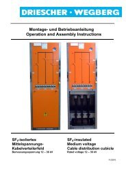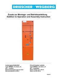
Montage- und Betriebsanleitung Operation and Assembly Instruction
Montage- und Betriebsanleitung Operation and Assembly Instruction
Montage- und Betriebsanleitung Operation and Assembly Instruction

Sie wollen auch ein ePaper? Erhöhen Sie die Reichweite Ihrer Titel.
YUMPU macht aus Druck-PDFs automatisch weboptimierte ePaper, die Google liebt.
Kapazitive Schnittstelle<br />
Spannungsfreiheit feststellen über die kapazitive<br />
Schnittstelle nach VDE 0682 Teil 415<br />
Die Prüfung auf Spannungsfreiheit nach HR-<br />
System (70...90 V am Messpunkt bei 2,5 μA) erfolgt<br />
mit kapazitiven Spannungsanzeigegeräten<br />
an den Messbuchsen L1, L2, L3.<br />
Benutzen Sie nur Prüfgeräte nach VDE<br />
0682 Teil 415 für HR-Systeme. Beachten<br />
Sie die <strong>Betriebsanleitung</strong> der Prüfgerätehersteller<br />
<strong>und</strong> VDE 0682 Teil 415. Prüfen<br />
Sie die Prüfgeräte vor Gebrauch auf<br />
Funktion!<br />
- Schutzstöpsel entfernen<br />
- Spannungsanzeigegerät nach <strong>Betriebsanleitung</strong><br />
des Herstellers mit Messbuchsen verbinden<br />
<strong>und</strong> auf Spannungsfreiheit prüfen.<br />
- Nach der Prüfung Spannungsanzeigegerät<br />
von den Messbuchsen trennen.<br />
- Schutzstöpsel auf Messbuchsen stecken, um<br />
das Verschmutzen der Messbuchsen zu verhindern.<br />
Keine Kurzschlussstecker verwenden! Die<br />
Schutzfunktion der spannungsbegrenzenden<br />
Sollbruchstelle wird bei Verwendung<br />
von Kurzschlusssteckern unwirksam !<br />
Funktionsprüfung: siehe Skizze auf Seite 12.<br />
Wiederholungsprüfung: In festen Zeitabständen<br />
durch o.g. Funktionsprüfung bei bekannter Betriebsspannung.<br />
(Letzte Wiederholungs- / Funktionsprüfung<br />
siehe Aufdruck am Koppelteil.)<br />
Integriertes Spannungsanzeigegerät<br />
Optional sind integrierte Spannungsanzeigegeräte<br />
zur Feststellung der Spannungsfreiheit nach VDE<br />
0682 Teil 415 erhältlich.<br />
Mit integrierten Spannungsanzeigesystemen entfällt<br />
die Wiederholungsprüfung. Bitte beachten Sie<br />
hierzu die entsprechende Bedienungsanleitung<br />
des Herstellers.<br />
DRIESCHER • WEGBERG<br />
Capacitive Interface<br />
Verify the isolation from supply via the capacitive<br />
interface according to IEC 61243-5<br />
The check for isolation from supply according to<br />
the HR-system (70…90 V at the measuring point<br />
with 2,5 μA) is performed with capacitive voltage<br />
indicators on the measuring sockets L1, L2, L3.<br />
Only use test instruments corresponding<br />
to IEC 61243-5 for HR Systems. Observe<br />
the operating manual issued by the<br />
manufacturer of the test instruments <strong>and</strong><br />
IEC 61243-5. Check the test instruments<br />
for proper operation before usage!<br />
- Remove the protective caps.<br />
- Connect the voltage indicator according to the<br />
operating manual of the manufacturer with the<br />
measuring sockets <strong>and</strong> check, if the switchgear<br />
is dead.<br />
- After the check, separate the voltage indicator<br />
from the measuring sockets.<br />
- Put the protective caps onto the measuring<br />
sockets to avoid the formation of dirt.<br />
Do not use any shorting plugs! The<br />
protective function of the declared breaking<br />
point that limits voltage becomes invalid<br />
with the use of shorting plugs.<br />
Functional Test: see sketch on page 12.<br />
Repeat Test: In fixed intervals with the abovementioned<br />
functional test <strong>and</strong> a predetermined<br />
operating voltage. (Last repeat/functional test see<br />
marking on the coupling part).<br />
Integrated voltage indication device<br />
As an option, integrated voltage indication devices<br />
are available to verify the isolation from supply<br />
according to IEC 61243-5.<br />
With integrated voltage indication systems the<br />
repeat test is omitted. Please observe the<br />
relevant operation instruction of the manufacturer.<br />
MINEX / G.I.S.E.L.A 13