Montage- und Betriebsanleitung Operation and Assembly Instruction
Montage- und Betriebsanleitung Operation and Assembly Instruction
Montage- und Betriebsanleitung Operation and Assembly Instruction

Sie wollen auch ein ePaper? Erhöhen Sie die Reichweite Ihrer Titel.
YUMPU macht aus Druck-PDFs automatisch weboptimierte ePaper, die Google liebt.
DRIESCHER • WEGBERG<br />
Kabelprüfung<br />
Kabelprüfung bei angeschlossenem Kabel<br />
ist eine besondere Beanspruchung der<br />
Trennstrecke innerhalb der Schaltkammern.<br />
Unzulässige Überspannungen infolge von<br />
reflektierenden Überspannungswellen vermeiden.<br />
Überspannungsableiter oder entsprechende<br />
Schutzbeschaltungen vorsehen.<br />
Gehen Sie behutsam <strong>und</strong> aufmerksam vor!<br />
Benutzen Sie nur die zum angeschlossenen<br />
Steckertyp gehörigen Kabelprüfelemente.<br />
Vorgehensweise<br />
Vorbereitende Maßnahmen<br />
⇒ Zu prüfenden Abgang gemäß dieser Anleitung<br />
freischalten, erden <strong>und</strong> kurzschließen.<br />
⇒ Sicherstellen, dass der Abgang in der Gegenstation<br />
ebenfalls freigeschaltet ist.<br />
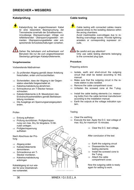
⇒ Kabelraumabdeckung abnehmen.<br />
⇒ Schraubkonus am T-Stecker herausschrauben.<br />
⇒ Kabelprüfelemente (z.B. Messbolzen) des<br />
Endverschlussherstellers gemäß <strong>Betriebsanleitung</strong><br />
montieren.<br />
⇒ Die Ausgänge am Spannungsanzeigesystem<br />
erden.<br />
Prüfen<br />
⇒ Erdung aufheben<br />
⇒ Prüfung durchführen. Prüfgleichspannung<br />
von max. 6U0 für längstens 15 Minuten<br />
anlegen.<br />
⇒ Prüfgleichspannung<br />
aufheben<br />
Nach Abschluss der Prüfung<br />
⇒ Abgang erden<br />
⇒ Kabelprüfelemente<br />
demontieren.<br />
⇒ Schraubkonus am T-<br />
Stecker montieren.<br />
⇒ Kabelraumabdeckung<br />
anbringen<br />
Kabelabgang ist nun wieder<br />
für eine Inbetriebnahme<br />
vorbereitet.<br />
36 MINEX / G.I.S.E.L.A<br />
Cable testing<br />
Procedure<br />
Cable testing with connected cables means<br />
special stress to the isolating distance within<br />
the arcing chambers.<br />
Avoid inadmissible overvoltages due to reflecting<br />
overvoltage waves. Provide lightning<br />
arresters or corresponding supressor circuits.<br />
Be careful <strong>and</strong> pay attention!<br />
Only use cable testing elements belonging<br />
to the connected plug type.<br />
Preparing actions<br />
⇒ Isolate, earth <strong>and</strong> short-circuit the outgoing<br />
circuit that shall be tested according to this<br />
manual.<br />
⇒ Make sure that the outgoing circuit in the remote<br />
station is also isolated.<br />
⇒ Remove the cable compartment cover.<br />
⇒ Unfasten the screwed cone at the T-plug.<br />
⇒ Install the cable testing elements (i.e. measuring<br />
bolts) from the cable terminal manufacturer<br />
according to the installation manual.<br />
⇒ Earth the outputs at the voltage indication system.<br />
Testing<br />
© DRIESCHER • WEGBERG<br />
⇒ Clear the earthing<br />
⇒ Execute the test. Apply the D.C. test voltage of<br />
max. 6U0 for maximum 15 minutes.<br />
⇒ Clear the D.C. test voltage.<br />
After conclusion of the test<br />
⇒ Earth the outgoing circuit<br />
⇒ Disassemble the cable<br />
testing elements<br />
⇒ Install the screwed cone to<br />
the T-plug.<br />
⇒ Attach the cable<br />
compartment cover.<br />
Now the outgoing cable is ready<br />
again for setting to work.