- Seite 1 und 2:
1 2 3 4 5 6 7 8 9 10 11 2017 12 www
- Seite 3 und 4:
AUSGESUCHTE NEUHEITEN AUS DIESEM KA
- Seite 5 und 6:
AUSGESUCHTE NEUHEITEN AUS DIESEM KA
- Seite 7 und 8:
Für das stehende und laufende Gut
- Seite 9 und 10:
www.gleistein.com Tauwerkeinsatz in
- Seite 11 und 12:
www.gleistein.com MegaTwin 07 Kern:
- Seite 13 und 14:
www.gleistein.com DynaLite • Kern
- Seite 15 und 16:
www.gleistein.com Harkon Kern: Poly
- Seite 17 und 18:
www.gleistein.com GeoPacks Fenderle
- Seite 19 und 20:
www.gleistein.com GeoSquare Polyest
- Seite 21 und 22:
www.gleistein.com Caribic Color Lie
- Seite 23 und 24:
www.gleistein.com Liekleinen Liekle
- Seite 25 und 26:
Liekleinen - Flechtleinen - Kausche
- Seite 27 und 28:
Kauschen - Drahtseilschneider Thimb
- Seite 29 und 30:
Drahtseile aus Edelstahl 1.4401 Sta
- Seite 31 und 32:
Wireteknik® Walzmaschinen Swaging
- Seite 33 und 34:
R R R Werkzeuge für Presshülsen T
- Seite 35 und 36:
Hi-Mod Schraubterminals, Edelstahl
- Seite 37 und 38:
Isolatoren Insulators Walzterminal/
- Seite 39 und 40:
Walzterminals - Edelstahl 1.4401 Sw
- Seite 41 und 42:
Walzterminals - Edelstahl 1.4401 Sw
- Seite 43 und 44:
Walzterminals - Edelstahl 1.4401 Sw
- Seite 45 und 46:
Wantenspanner - Montageteile - QRT
- Seite 47 und 48:
Wantenspanner mit verchromter Bronz
- Seite 49 und 50:
Toggle - Edelstahl 1.4401 Toggle -
- Seite 51 und 52:
Wantenspannungsmesser - Spannschlos
- Seite 53 und 54:
Splinte Safety pins Ringsplinte-Rin
- Seite 55 und 56:
Pelikanhaken, Sliphaken, Achterstag
- Seite 57 und 58:
Achterstag-Spanner backstay adjuste
- Seite 59 und 60:
Spezialschäkel, Bandschäkel Speci
- Seite 61 und 62:
eSelbstsichernd - s eSelbstsichernd
- Seite 63 und 64:
Schäkel, geschmiedet aus Edelstahl
- Seite 65 und 66:
Schäkel, Karabinerhaken Shackles,
- Seite 67 und 68:
Aluminium Karabinerhaken Aluminium
- Seite 69 und 70:
Symmetrische Karabinerhaken, Edelst
- Seite 71 und 72:
Schnappschäkel Snap shackles Schwe
- Seite 73 und 74:
Schnappschäkel Edelstahl geschmied
- Seite 75 und 76:
Schraubglieder Quick links Rechteck
- Seite 77 und 78:
Wirbelschäkel, Edelstahl geschmied
- Seite 79 und 80:
Acht Blockgrößen, die jeden Bedar
- Seite 81 und 82:
Barton Blöcke "Size 0" Barton bloc
- Seite 83 und 84:
Barton Blöcke "Standard" Barton bl
- Seite 85 und 86:
Barton Blöcke "Standard" Barton bl
- Seite 87 und 88:
Barton Blöcke "Cruiser" Barton blo
- Seite 89 und 90:
Drahtseilblöcke "Snatchblöcke" Wi
- Seite 91 und 92:
Kugellagerblöcke ball bearing bloc
- Seite 93 und 94:
Kugellagerblöcke ball bearing bloc
- Seite 95 und 96:
High Tension Blöcke High Tension b
- Seite 97 und 98:
Einfach gelagerte Blöcke Plain bea
- Seite 99 und 100:
Knarrblock ratchet block HA 2150 HA
- Seite 101 und 102:
Wichard Blöcke Wichard blocks WICH
- Seite 103 und 104:
Wichard Blöcke Wichard blocks WICH
- Seite 105 und 106:
SeaSure Blöcke SeaSure blocks SeaS
- Seite 107 und 108:
Holz Blöcke Wodden-blocks Holzblö
- Seite 109 und 110:
Blöcke blocks Kunststoffblöcke -
- Seite 111 und 112:
Taljenkästen, Niederholer- und Bau
- Seite 113 und 114:
Spibaumbeschläge Spi pole fittings
- Seite 115 und 116:
Rollenkästen sheaveboxes Rollenkä
- Seite 117 und 118:
Mastfußschiene Maststep Mastfußsc
- Seite 119 und 120:
Wantenversteller Stay adjuster Want
- Seite 121 und 122:
Trapezbeschläge Trapeze accessorie
- Seite 123 und 124:
Lazy Jack - Reffer Lazy Jack - Reef
- Seite 125 und 126:
Kicker Boomkicker Kicker BARTON BOO
- Seite 127 und 128:
Einfädler - Mastrutscher-Stopper -
- Seite 129 und 130:
Für den Segelmacher, Persenningmac
- Seite 131 und 132:
Segellatten für nicht durchgelatte
- Seite 133 und 134:
Segellatten für durchgelattete Seg
- Seite 135 und 136:
Segellatten Sail battens Auswahlemp
- Seite 137 und 138:
Segellatten für durchgelattete Seg
- Seite 139 und 140:
Roll Latten - Segellatten Roller ba
- Seite 141 und 142:
Lattenendkappen Caps for sail batte
- Seite 143 und 144:
Lattenspannersystem Batten fittings
- Seite 145 und 146:
Luffshuttle Lattenrutscher - Schoth
- Seite 147 und 148:
Mastrutscher - Mastschienen Mast sl
- Seite 149 und 150:
Liekleinenklemmen Leechline cleats
- Seite 151 und 152:
Liekschoner - Triangeln Leech prote
- Seite 153 und 154:
Rundringe - D-Ringe Round rings - D
- Seite 155 und 156:
Super-Ring-System Super-ring-system
- Seite 157 und 158:
Nieten - Kauschen und Werkzeuge - K
- Seite 159 und 160:
Kopfbretter Headboard Kopfbretter -
- Seite 161 und 162:
Vorliekbänder - Keder Lufftapes -
- Seite 163 und 164:
Nummerntuche - Polyesternetz - Fens
- Seite 165 und 166:
Schablonenfolie - Schaumstoff - Led
- Seite 167 und 168:
Doppelseitige Klebebänder Double s
- Seite 169 und 170:
Klebebänder, Kleber, Imprägnierun
- Seite 171 und 172:
SOLBOND Nähgarn SOLBOND thread 1 2
- Seite 173 und 174:
Scheren Scissors Alle Scheren sind
- Seite 175 und 176:
Heiß-Schneider - Segelmacherzange
- Seite 177 und 178:
Takler- und Segelmacher-Werkzeuge R
- Seite 179 und 180:
Takelgarn - Handnähgarn und Ahle T
- Seite 181 und 182:
Messingösen - Laschhaken - Schlauf
- Seite 183 und 184:
Gummileine - Krampen Shock cord - c
- Seite 185 und 186:
Gurt-Beschläge Strap-Fittings Fuß
- Seite 187 und 188:
Gurtschnallen Buckles for webbing S
- Seite 189 und 190:
Gurtbandhaken - Gurtbandblöcke - G
- Seite 191 und 192:
Gurtband Webbing Gurtband Polypropy
- Seite 193 und 194:
Spanngurte lashing straps Spanngurt
- Seite 195 und 196:
Klettbänder Touch & close fastener
- Seite 197 und 198:
Reißverschlüsse zippers Spiralrei
- Seite 199 und 200:
WEATHERMAX Polyester WEATHERMAX Pol
- Seite 201 und 202:
WEATHERMAX Polyester WEATHERMAX Pol
- Seite 203 und 204:
MasAcril® MasAcril® Art.-Nr. Rll.
- Seite 205 und 206:
Persenning-Tuche, PVC-beschichtet t
- Seite 207 und 208:
Mikro Klemmblock - Persenninglüfte
- Seite 209 und 210:
STOPGULL AIR Halterungen STOPGULL A
- Seite 211 und 212:
Persenningknöpfe - Schnellverschl
- Seite 213 und 214:
TENAX® MARINE Schnellverschlüsse
- Seite 215 und 216:
PERFIX® Bisher wurde auf Booten Be
- Seite 217 und 218:
R DOT® Verschlüsse DOT® Fastener
- Seite 219 und 220:
PULL-THE-DOT® + LIFT-THE-DOT® + C
- Seite 221 und 222:
Rohrbeschläge für Sprayhood und K
- Seite 223 und 224:
Rohrbeschläge für Sprayhood und K
- Seite 225 und 226:
Rohrbeschläge für Sprayhood und K
- Seite 227 und 228:
Rohrgelenke - Biegemaschine - Rohre
- Seite 229 und 230:
Für die Decksausrüstung Jollen un
- Seite 231 und 232:
Relings- und Rohrbeschläge aus Ede
- Seite 233 und 234:
Umlenkösen - Umlenkrollen - Doppel
- Seite 235 und 236:
Handläufe - Antennenbasis Hand Rai
- Seite 237 und 238:
Leitösen Fairleads Leitösen - Fai
- Seite 239 und 240:
Decksdurchführungen - U-Bolzen - V
- Seite 241 und 242:
Gewindestange - Ringmutter - Augbol
- Seite 243 und 244:
Klampen cleats L LL Belegklampen -
- Seite 245 und 246:
Klampen - Poller - Lippen Cleats -
- Seite 247 und 248:
Schotklemmen cam cleats SERVO-Cleat
- Seite 249 und 250:
Schotklemmen cam cleats Allen Kugel
- Seite 251 und 252:
Clamcleat® Tauklemmen Clamcleat®
- Seite 253 und 254:
Clamcleat® Tauklemmen Clamcleat®
- Seite 255 und 256:
Clamcleat® Tauklemmen Clamcleat®
- Seite 257 und 258:
Fallenstopper Clutches Spinlock Fal
- Seite 259 und 260:
Fallenumlenkblöcke Deck organisers
- Seite 261 und 262:
Fockschotrutscher Jib Sheet Sliders
- Seite 263 und 264:
Barton Traveller Barton Travellers
- Seite 265 und 266:
Barton Genua Rutscher Barton Genoa
- Seite 267 und 268:
Barton Genua Rutscher Barton Genoa
- Seite 269 und 270:
Andersen - Winden aus Edelstahl And
- Seite 271 und 272:
Andersen - Selbstholende Winschen A
- Seite 273 und 274:
Winschkurbeln Winch handles Winschk
- Seite 275 und 276:
Auftriebskörper Buoyancy bags Holt
- Seite 277 und 278:
Optimistenzubehör Optimist parts Z
- Seite 279 und 280:
Optimistenzubehör Optimist parts R
- Seite 281 und 282:
Optimistenzubehör Optimist parts F
- Seite 283 und 284:
Optimistenzubehör Optimist parts S
- Seite 285 und 286:
Motorbootzubehör Anzeigeinstrument
- Seite 287 und 288:
Opferanoden Sacrificial anodes Well
- Seite 289 und 290:
Opferanoden - Stopfbuchsenpackung -
- Seite 291 und 292:
13 Treibstoffanschlüsse Fuel line
- Seite 293 und 294:
Schläuche Hoses 1 Treibstoffschlau
- Seite 295 und 296:
Hydrofoils - Trimmklappen Hydrofoil
- Seite 297 und 298:
PROP GUARD - PROP SOX - Scherstifte
- Seite 299 und 300:
McGard Außenbordersicherungen McGa
- Seite 301 und 302:
1 2 3 4 5 6 7 8 9 10 11 12 13 14 LI
- Seite 303 und 304:
Wasserski Zubehör Waterski equipme
- Seite 305 und 306:
Steuerräder Ultraflex Steering whe
- Seite 307 und 308:
Hinweise zur Auswahl von mechanisch
- Seite 309 und 310:
Steuerungsanlagen Steering systems
- Seite 311 und 312:
Steuerungsanlagen Steering systems
- Seite 313 und 314:
Steuerungsanlagen Steering systems
- Seite 315 und 316:
Steuerungsanlagen Steering systems
- Seite 317 und 318:
Schaltungen Lever controls Einhebel
- Seite 319 und 320:
Schaltungen Lever controls Einhebel
- Seite 321 und 322:
Schaltungen Lever controls Art.-Nr.
- Seite 323 und 324:
Schaltkabel Engine control cables c
- Seite 325 und 326:
Kabeldurchführungen Steering gromm
- Seite 327 und 328:
Ultraflex Hydraulik Steuerung Ultra
- Seite 329 und 330:
Hydraulik Steuerung Sätze hydrauli
- Seite 331 und 332:
Anzeigeinstrumente Marine instrumen
- Seite 333 und 334:
Steuersitze - Sitzsockel - Fußstü
- Seite 335 und 336:
Tischbefestigungen Table Brackets T
- Seite 337 und 338:
Impeller für Innenbordmotoren Impe
- Seite 339 und 340:
Impeller für Außenbordmotoren Imp
- Seite 341 und 342:
Schalldämpfer Silencers Mittelscha
- Seite 343 und 344:
Dieselfilter - Kühlwasserfilter -
- Seite 345 und 346:
Rollen und Bugpuffer Roles and bowp
- Seite 347 und 348:
Scheibenwaschanlage - Antennenbasis
- Seite 349 und 350:
ZUM STEUERN & FORTBEWEGEN Bugstrahl
- Seite 351 und 352:
Spiegelbeschläge Transom fittings
- Seite 353 und 354:
Rudersicherungen - Ruderblattschutz
- Seite 355 und 356:
Pinnenausleger Tiller extensions Al
- Seite 357 und 358:
Pinnenausleger Tiller extensions LI
- Seite 359 und 360:
Paddel Paddels IndiTour 1 Qualität
- Seite 361 und 362:
Bootsriemen - Displayständer Oars
- Seite 363 und 364:
Rudergabeln - Buchsen Row Locks - S
- Seite 365 und 366:
ENDURA MAX • 2 Leistungsklassen
- Seite 367 und 368:
Bugstrahlruder Bowthrusters Schutz-
- Seite 369 und 370:
Bugstrahlruder Bowthrusters Ausfahr
- Seite 371 und 372:
ZUM ANKERN & FESTMACHEN Anker ab 38
- Seite 373 und 374:
Ankerwinden Windlasses Ratschläge
- Seite 375 und 376:
Ankerwinden, Aufbau Windlasses, on-
- Seite 377 und 378:
Ankerwinden, Einbau Windlasses, thr
- Seite 379 und 380:
Verholspill Capstans Pontoon Verhol
- Seite 381 und 382:
Funkfernsteuerung Radio remote cont
- Seite 383 und 384:
Kettenzählwerk Chain Counter 1 2 3
- Seite 385 und 386:
ROCNA® Anker ROCNA® Anchors Der S
- Seite 387 und 388:
Anker Anchors Klappdraggen - Dragge
- Seite 389 und 390:
Ankerhalter Anchor holders Halter f
- Seite 391 und 392:
Schleusenhaken - Rocker stopper - F
- Seite 393 und 394:
Ankerwirbel - Ankerverbinder Anchor
- Seite 395 und 396:
Ketten Chains Ketten, kurzgliedrig,
- Seite 397 und 398:
Anlegefedern mooring compensators F
- Seite 399 und 400:
Bojenfänger Buoy catcher Bojen-Kar
- Seite 401 und 402:
Bootshaken Boat hooks Bootshaken -
- Seite 403 und 404:
Stegfender Dock Ring - Fender Profi
- Seite 405 und 406:
Polyform-Fender und Bojen Polyform
- Seite 407 und 408:
Polyform-Fender und Bojen Polyform
- Seite 409 und 410:
Fenderclips Fender clips Fenderhake
- Seite 411 und 412:
BRAVO Luftpumpen BRAVO Air pumps 12
- Seite 413 und 414:
Für die Beleuchtung & Elektronik 1
- Seite 415 und 416:
Lichtführung Navigation lights use
- Seite 417 und 418:
Navigationslaternen Navigation ligh
- Seite 419 und 420:
Navigationslaternen Navigation ligh
- Seite 421 und 422:
Navigationslaternen Navigation ligh
- Seite 423 und 424:
Navigationslaternen Navigation ligh
- Seite 425 und 426:
Navigationslaternen Navigation ligh
- Seite 427 und 428:
Navigationslaternen Navigation ligh
- Seite 429 und 430:
Navigationslaternen Navigation ligh
- Seite 431 und 432:
Batteriebetriebene Navigationslater
- Seite 433 und 434:
Navigationslaternen Navigation ligh
- Seite 435 und 436:
Unterwasserleuchten - Deckstrahler
- Seite 437 und 438:
Deckstrahler - Salingleuchten Flood
- Seite 439 und 440:
Innenleuchten Interior lights Paris
- Seite 441 und 442:
QUICK LIGHT Leuchten QUICK LIGHT li
- Seite 443 und 444:
QUICK LIGHT Leuchten QUICK LIGHT li
- Seite 445 und 446:
Arbeitsleuchten Working Lights Stab
- Seite 447 und 448:
Leuchtmittel Light sources Leuchtmi
- Seite 449 und 450:
Clarion Marine Audio und Entertainm
- Seite 451 und 452:
Clarion Marine Audio und Entertainm
- Seite 453 und 454:
Ladestromverteiler Charge Separator
- Seite 455 und 456:
Batterieschalter Battery Switches B
- Seite 457 und 458:
Schnellkupplung - Batteriekasten ba
- Seite 459 und 460:
12 V Stecker und Steckdosen 12 V Pl
- Seite 461 und 462:
Steckverbindungen Deck Connectors S
- Seite 463 und 464:
Decksdurchführungen Cable outlets
- Seite 465 und 466:
Carling Schalter Carling Switches C
- Seite 467 und 468:
Für die elektrische Ausrüstung El
- Seite 469 und 470:
Schaltpaneele Switch panels 3-fach,
- Seite 471 und 472:
Für die elektrische Ausrüstung El
- Seite 473 und 474:
Für die elektrische Ausrüstung El
- Seite 475 und 476:
CEE - Stecker CEE - Connectors CEE
- Seite 477 und 478:
CEE - Stecker CEE - plugs CEE Adapt
- Seite 479 und 480:
BERKER Integro Flow Gerade auf klei
- Seite 481 und 482:
Für die Sicherheit, Flaggen und Zu
- Seite 483 und 484:
Flaggen Flags Bundesflaggen / Europ
- Seite 485 und 486:
Flaggen - Ankerball - Signalkegel -
- Seite 487 und 488:
Flaggenstöcke Flaggstaffs Flaggens
- Seite 489 und 490:
Radar Reflektoren Radar Reflectors
- Seite 491 und 492:
Signalhörner Signal horns Signalh
- Seite 493 und 494:
Rettungswesten, aufblasbar lifejack
- Seite 495 und 496:
Feststoff Rettungswesten Inherent l
- Seite 497 und 498:
Wurfleine - Grab Bag - Rettungsring
- Seite 499 und 500:
ClamSeal - Aquamate - Erste Hilfe C
- Seite 501 und 502:
u u Sicherheitsleinen Lifeline Sich
- Seite 503 und 504:
Badeleitern Boarding ladders 254 31
- Seite 505 und 506:
Sanitäre Ausstattung Abwasserpumpe
- Seite 507 und 508:
Barka Spülen und Zubehör Barka si
- Seite 509 und 510:
Whale Frischwassersysteme Whale fre
- Seite 511 und 512:
Whale Frischwassersysteme Whale fre
- Seite 513 und 514:
Whale Frischwassersysteme Whale fre
- Seite 515 und 516:
Whale Frischwassersysteme Whale fre
- Seite 517 und 518:
Whale Frischwassersysteme Whale fre
- Seite 519 und 520:
Whale Frischwassersysteme Whale fre
- Seite 521 und 522:
Boiler Boiler NAUTIC BOILER B3 Geh
- Seite 523 und 524:
Whale Abwassersysteme Whale waste s
- Seite 525 und 526:
Whale Bilgesysteme Whale bilge syst
- Seite 527 und 528:
Whale Bilgesysteme Whale bilge syst
- Seite 529 und 530:
Whale Bilgesysteme Whale bilge syst
- Seite 531 und 532:
Whale Bilgesysteme Whale bilge syst
- Seite 533 und 534:
Bilgepumpen - Bilgealarm Bilge Pump
- Seite 535 und 536:
Drainman Lenzer - Lenzer Drainman b
- Seite 537 und 538:
Bilgewasser ist die Hauptursache f
- Seite 539 und 540:
Pumpenset pumpkit Whale Pumpenset -
- Seite 541 und 542:
Toiletten Abwasserpumpen Toilet Was
- Seite 543 und 544:
Toiletten toilets SANIMARIN COMFORT
- Seite 545 und 546:
Brauchwasser Leitungssystem TRUDESI
- Seite 547 und 548:
Brauchwasser Leitungssystem TRUDESI
- Seite 549 und 550:
Brauchwasser Leitungssystem TRUDESI
- Seite 551 und 552:
Brauchwasser Leitungssystem Messing
- Seite 553 und 554:
Brauchwasser Leitungssystem Messing
- Seite 555 und 556: Brauchwasser Leitungssystem Messing
- Seite 557 und 558: Brauchwasser Leitungssystem Edelsta
- Seite 559 und 560: Schlauchverbinder Hose Connectors S
- Seite 561 und 562: Schlauch hose 1 Treibstoffschlauch
- Seite 563 und 564: Schlauchschellen - Wassertanks Hose
- Seite 565 und 566: Tankdeckelschlüssel - Jollenstaube
- Seite 567 und 568: Inspektionsdeckel Hatch covers Insp
- Seite 569 und 570: Zubehör für Flüssiggasanlagen Ac
- Seite 571 und 572: Für den Innenausbau und die Lüftu
- Seite 573 und 574: Griffe Handles Einlasskastengriff -
- Seite 575 und 576: Haken hooks Haken mit Beffe - ball
- Seite 577 und 578: Haken - Schraubenrosetten - Kistene
- Seite 579 und 580: Aufbau Türschlösser - Zylinder Ka
- Seite 581 und 582: Möbelschlösser push locks Druckkn
- Seite 583 und 584: Vorhangschlösser Padlocks Vorhangs
- Seite 585 und 586: Schubriegel - Fingerschnäpper - Vo
- Seite 587 und 588: Hebelverschlüsse Snag free fastene
- Seite 589 und 590: Türfeststeller Door holder Kugelsc
- Seite 591 und 592: Scharniere hinges Winkel - Angles E
- Seite 593 und 594: Scharniere hinges Scharniere mit lo
- Seite 595 und 596: Scharniere hinges Scharniere - hing
- Seite 597 und 598: Scharniere hinges Scharniere - hing
- Seite 599 und 600: Scharniere + Bänder hinges Kistenb
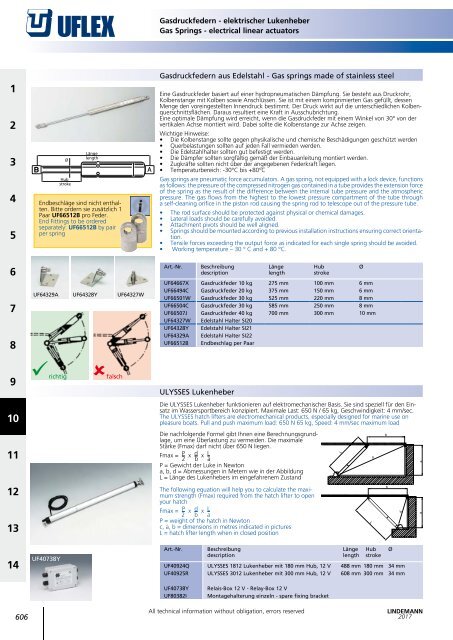
- Seite 601 und 602: 1 2 PERFEKTE BLENDEN MONTAGE Produk
- Seite 603 und 604: 1 2 LOW PROFILE LOW PROFILE VERY LO
- Seite 605: 1 2 WERKZEUGE TOOLS 3 Standard Prof
- Seite 609 und 610: Lüfterbleche - Gegenplatten Hit &
- Seite 611 und 612: Motorraum Lüfter - Lüftungsschlau
- Seite 613 und 614: Für die Kursbestimmung AEROVANE ab
- Seite 615 und 616: Windex Windanzeige Windex wind indi
- Seite 617 und 618: Windanzeiger Wind indicators HAWK W
- Seite 619 und 620: Windanzeiger Wind indicators Allen
- Seite 621 und 622: Sextanten - Künstlicher Horizont S
- Seite 623 und 624: Uflex Kompasse Uflex compasses 94 m
- Seite 625 und 626: Windmesser - Peilkompasse - Kurslin
- Seite 627 und 628: 180 0 1 2 UPPER NUMB ER : MOR E NOR
- Seite 629 und 630: Navigationsmappe - Zirkel Navigatio
- Seite 631 und 632: Für die Werterhaltung Abdeckplanen
- Seite 633 und 634: Atemmasken - Holzpfropfen Protectio
- Seite 635 und 636: Spezialöle Special purpose oils BA
- Seite 637 und 638: Sikaflex Technique Marine Ausführl
- Seite 639 und 640: Sikaflex Technique Klebe-Dichtungss
- Seite 641 und 642: Trittstufen - Scheuerleisten Step P
- Seite 643 und 644: Scheuerleisten Fendering profiles W
- Seite 645 und 646: Scheuerleisten Fendering profiles A
- Seite 647 und 648: DEK KING Bond - Die Alternative zu
- Seite 649 und 650: DEK KING 2G - Die Alternative zu Ho
- Seite 651 und 652: Anti-Rutsch Tapes Non-Slip tapes 3M
- Seite 653 und 654: PSP Marine Tapes - TESA Aluminium T
- Seite 655 und 656: Planenösen - Luftentfeuchter Tarpa
- Seite 657 und 658:
SWOBBIT Decksreinigung SWOBBIT Deck
- Seite 659 und 660:
SWOBBIT Decksreinigung SWOBBIT Deck
- Seite 661 und 662:
Für den persönlichen Bedarf Akupr
- Seite 663 und 664:
Barigo - Schiffsuhren Barigo -Ship'
- Seite 665 und 666:
Multiwerkzeuge multi tools V ICTOR
- Seite 667 und 668:
Holzkohlegrill - Isolierflaschen -
- Seite 669 und 670:
Lagun - Cockpittische Lagun cockpit
- Seite 671 und 672:
Mückenschutz Mosquito repellent Mo
- Seite 673 und 674:
Akupressurband - Segelhandschuhe -
- Seite 675 und 676:
Schlüsselanhänger - Schlüsselrin
- Seite 677 und 678:
Flaschenöffner - Aschenbecher - Ma
- Seite 679 und 680:
Spezialbedarf VERKAUFSUNTERSTÜTZUN
- Seite 681 und 682:
Präsentationshilfen für den Fachh
- Seite 683:
LAST MINUTE NEWS MXLEvo Soft-Block


![Gotthardt-Technikkatalog_2018_komplett_low[1]](https://img.yumpu.com/60527477/1/184x260/gotthardt-technikkatalog-2018-komplett-low1.jpg?quality=85)