Kreiselpumpen Technische Auslegung Centrifugal Pumps ... - Friatec
Kreiselpumpen Technische Auslegung Centrifugal Pumps ... - Friatec
Kreiselpumpen Technische Auslegung Centrifugal Pumps ... - Friatec

Erfolgreiche ePaper selbst erstellen
Machen Sie aus Ihren PDF Publikationen ein blätterbares Flipbook mit unserer einzigartigen Google optimierten e-Paper Software.
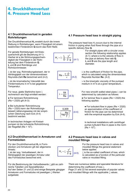
4. Druckhöhenverlust<br />
4. Pressure Head Loss<br />
4.1 Druckhöhenverlust in geraden<br />
Rohrleitungen<br />
Der Druckhöhenverlust HJ ensteht durch die innere<br />
Reibung in Rohrleitungen, wenn Flüssigkeit mit einem<br />
bestimmten Förderstrom Q durch das Rohr fließt.<br />
Für gerade Rohrleitungen mit Kreisquerschnitt<br />
gilt die Beziehung (4-1):<br />
Hierbei ist v die Strömungsgeschwindigkeit<br />
der Flüssigkeit in der Rohrleitung<br />
bei dem Förderstrom Q.<br />
L und D sind Rohrlänge und<br />
Rohrdurchmesser.<br />
� ist der sog. Rohrreibungsbeiwert, der in<br />
Abhängigkeit von der dimensionslosen<br />
Reynolds-Zahl Re berechnet wird (4-2).<br />
� ist die kinematische Viskosität des<br />
Fördermediums in m 2 /s bei gegebener<br />
Temperatur.<br />
Für neue, glatte Stahlrohre kann �<br />
rechnerisch wie folgt ermittelt werden:<br />
� Für laminare Rohrströmung<br />
(Re < 2320) gilt (4-3):<br />
� Bei turbulenter Rohrströmung<br />
(Re > 2320) kann der Rohrreibungsbeiwert<br />
näherungsweise mit der empirischen<br />
Gleichung nach Eck (4-4)<br />
bestimmt werden.<br />
In technischen Anlagen mit <strong>Kreiselpumpen</strong><br />
ist die turbulente Rohrströmung<br />
der Regelfall (Re > 10 4 ).<br />
4.2 Druckhöhenverlust in Armaturen und<br />
Formstücken<br />
Für den Druckhöhenverlust HJ in Formstücken<br />
und Armaturen gilt der allgemeine<br />
Ansatz:<br />
� ist der sog. Verlustbeiwert, der in<br />
Abhängigkeit der jeweiligen Armatur oder<br />
des Formstückes berechnet wird.<br />
20<br />
H<br />
J<br />
2<br />
L v<br />
� � � �<br />
D 2 � g<br />
v �D<br />
Re �<br />
�<br />
64<br />
� �<br />
Re<br />
0,<br />
309<br />
� �<br />
2<br />
� Re �<br />
�log<br />
�<br />
� 7 �<br />
H<br />
J<br />
� � �<br />
Für die Bestimmung der Verlustbeiwerte ��gibt es zahlreiche<br />
Tabellen und Spezialliteratur.<br />
Auf den Seiten 21 und 22 sind einige Beispiele gängiger<br />
Armaturen und Formstücke mit jeweiligen �-Werten<br />
aufgelistet.<br />
4.1 Pressure head loss in straight piping<br />
The pressure head loss HJ occurs due to the internal<br />
friction in piping when fluid flows through the pipe at a<br />
specific delivery flow Q.<br />
(4-3)<br />
(4-1)<br />
(4-2)<br />
(4-4)<br />
For straight pipes with a circular cross<br />
section the following relationship applies<br />
(4-1): where v is the velocity of flow in<br />
the pipe at delivery flow rate Q.<br />
L and D are the pipe length and<br />
diameter.<br />
� is the coefficient of friction for the pipe,<br />
which is calculated using the dimensionless<br />
Reynolds Number Re. (4-2)<br />
� is the kinematic viscosity of the pumped<br />
medium in m 2 /s at a given temperature..<br />
For new smooth walled steel pipes � can be<br />
determined by calculation as follows:<br />
� For laminar flow in pipes (Re < 2320) the<br />
following applies:<br />
� For turbulent flow in pipes (Re > 2320)<br />
an approximation of the coefficient of<br />
friction for the pipe can be determined<br />
with the empirical equation by Eck (4-4).<br />
In technical installations with centrifugal<br />
pumps turbulent flow in pipes is the norm<br />
(Re > 10 4 ).<br />
4.2 Pressure head loss in valves and<br />
moulded fittings<br />
2<br />
v<br />
2 � g<br />
(4-5)<br />
For the pressure head loss in valves and<br />
moulded fittings the general statement<br />
below applies:<br />
� is the so-called coefficient of loss, which<br />
is calculated as a function of the particular<br />
valve or moulded fitting.<br />
There are numerous tables and specialist literature for<br />
determining the coefficient of loss ��<br />
Page 21 and 22 list several examples of popular valves<br />
and moulded fittings with the applicable ��values.