Kreiselpumpen Technische Auslegung Centrifugal Pumps ... - Friatec
Kreiselpumpen Technische Auslegung Centrifugal Pumps ... - Friatec
Kreiselpumpen Technische Auslegung Centrifugal Pumps ... - Friatec

Sie wollen auch ein ePaper? Erhöhen Sie die Reichweite Ihrer Titel.
YUMPU macht aus Druck-PDFs automatisch weboptimierte ePaper, die Google liebt.
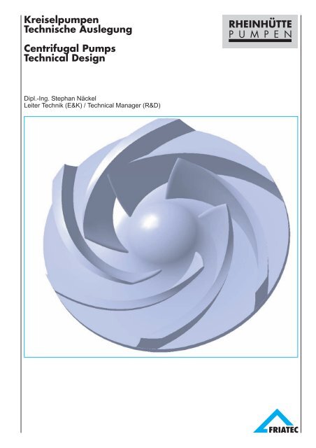
<strong>Kreiselpumpen</strong><br />
<strong>Technische</strong> <strong>Auslegung</strong><br />
<strong>Centrifugal</strong> <strong>Pumps</strong><br />
Technical Design<br />
Dipl.-Ing. Stephan Näckel<br />
Leiter Technik (E&K) / Technical Manager (R&D)<br />
RHEINHÜTTE<br />
P U M P E N
Inhaltsverzeichnis<br />
Contents<br />
A. Verwendete Formelzeichen und Indizes<br />
B. Anlagenbeispiele<br />
1 Physikalische Grundlagen<br />
1.1 Wirkprinzip<br />
1.2 Energieübertragung im Laufrad<br />
2 Grundbegriffe<br />
2.1 Förderstrom Q<br />
2.2 Förderhöhe H<br />
2.2.1 Förderhöhe der Pumpe<br />
2.2.2 Förderhöhe der Anlage<br />
2.3 Drehzahl n<br />
2.4 Leistungsbedarf P<br />
2.5 Wirkungsgrad η<br />
2.6 Spezifische Drehzahl n q<br />
2.7 Pumpenkennlinie<br />
2.8 Anlagenkennlinie (Rohrleitungskennlinie)<br />
2.9 Betriebspunkt<br />
3 Saug- und Zulaufverhältnisse<br />
3.1 Kavitation<br />
3.2 NPSH-Wert der Pumpe (NPSHR)<br />
3.3 NPSH-Wert der Anlage (NPSHA)<br />
3.4 Zulaufhöhe - hydrodynamische Entlastung<br />
4 Druckhöhenverlust<br />
4.1 Druckhöhenverlust in geraden<br />
Rohrleitungen<br />
4.2 Druckhöhenverlust in Armaturen und<br />
Formstücken<br />
5 <strong>Auslegung</strong> und Regelung<br />
5.1 Auswahl der Pumpengröße<br />
5.2 Änderung der Drehzahl<br />
5.3 Abdrehen des Laufrades<br />
5.4 Parallelbetrieb<br />
5.5 Serienbetrieb<br />
5.6 Bypassregelung<br />
5.7 Förderung viskoser Flüssigkeiten<br />
6 Hydraulische Kräfte<br />
6.1 Radialkraft<br />
6.2 Axialkraft<br />
7 Gestaltung des Pumpenzulaufs<br />
7.1 Saug- und Zulaufleitungen<br />
7.2 Zulauf- oder Speisebehälter<br />
7.3 Saug- und Zulaufbecken<br />
7.4 Behälter für vertikale Pumpen<br />
2<br />
Seite / Page<br />
3<br />
4<br />
7<br />
7<br />
7<br />
10<br />
10<br />
10<br />
10<br />
11<br />
11<br />
11<br />
12<br />
12<br />
13<br />
15<br />
15<br />
16<br />
16<br />
16<br />
17<br />
19<br />
20<br />
20<br />
20<br />
24<br />
24<br />
25<br />
26<br />
27<br />
27<br />
28<br />
29<br />
30<br />
30<br />
31<br />
32<br />
32<br />
33<br />
34<br />
35<br />
A. Symbols and indices used<br />
B. Examples of pump installations<br />
1 Physical principles<br />
1.1 Working principle<br />
1.2 Energy transfer in the impeller<br />
2 Basic terms<br />
2.1 Delivery Q<br />
2.2 Delivery head H<br />
2.2.1 Delivery head of the pump<br />
2.2.2 Delivery head of the installation<br />
2.3 Speed of rotation n<br />
2.4 Power requirement P<br />
2.5 Efficiency η<br />
2.6 Specific speed of rotation n q<br />
2.7 Pump characteristic curve<br />
2.8 Installation (pipeline) characteristic curve<br />
2.9 Operating point<br />
3 Suction and inflow conditions<br />
3.1 Cavitation<br />
3.2 NPSH value for the pump (NPSHR)<br />
3.3 NPSH value for the installation (NPSHA)<br />
3.4 Inflow head - hydrodynamic relief<br />
4 Pressure head loss<br />
4.1 Pressure head loss in straight pipe runs<br />
4.2 Pressure head loss in valves and<br />
moulded fittings<br />
5 Design and regulation<br />
5.1 Selection of the pump size<br />
5.2 Changing the speed of rotation<br />
5.3 Turning down the impeller<br />
5.4 Parallel operation<br />
5.5 Series operation<br />
5.6 Bypass regulation<br />
5.7 Pumping viscous fluids<br />
6 Hydraulic forces<br />
6.1 Radial force<br />
6.2 Axial force<br />
7 Design of the pump inflow<br />
7.1 Suction and inflow pipes<br />
7.2 Inflow or feeder tank<br />
7.3 Suction and inflow reservoir<br />
7.4 Tank for vertical pumps
A. Verwendete Formelzeichen und Indizes<br />
A. Symbols and Indices used<br />
Formelzeichen<br />
Symbol<br />
Einheit<br />
Unit<br />
Benennung Designation<br />
b2 m Laufradaustrittsbreite Impeller outlet width<br />
c m/s Absolutgeschwindigkeit Absolute velocity<br />
D m Laufraddurchmesser, Rohrdurchmesser Impeller diameter, pipe diameter<br />
F N Kraft Force<br />
g m/s 2 Fallbeschleunigung = 9,81 m/s 2 Gravitational acceleration = 9.81 m/s 2<br />
H m Förderhöhe Delivery head<br />
HA m Förderhöhe der Anlage Delivery head of the installation<br />
Hgeo m geodätische Förderhöhe Geodetic delivery head<br />
K - Radialkraftkoeffizient Radial force coefficient<br />
L m Rohrleitungslänge Piping length<br />
m kg Masse Mass<br />
n 1/min Drehzahl Rotation speed<br />
NPSHA m NPSH-Wert der Anlage NPSH value for the installation<br />
NPSHR m NPSH-Wert der Pumpe NPSH value for the pump<br />
nq 1/min spezifische Drehzahl Specific rotation speed<br />
p bar (Pa) manometrischer Druck (relativ) Manometric pressure (relative)<br />
P kW Leistung Power<br />
pamb bar (Pa) Atmosphärendruck (absolut) Atmospheric pressure (absolute)<br />
Pu kW Förderleistung der Pumpe Delivery power of the pump<br />
pv bar (Pa) Verdampfungsdruck (absolut) Vapour pressure (absolute)<br />
q - Fördergrad (Q/Qopt) Delivery coefficient (Q/Qopt)<br />
Q m 3 /h Förderstrom Delivery flow<br />
r m Radius Radius<br />
Re - Reynolds-Zahl Reynolds-number<br />
u m/s Umfangsgeschwindigkeit Circumferential velocity<br />
v m/s Strömungsgeschwindigkeit Velocity of flow<br />
w m/s Relativgeschwindigkeit Relative velocity<br />
z m Höhenunterschied Difference in head<br />
Z m Zulaufaufnahme Inflow head<br />
�s2 ° Schaufelwinkel am Laufradaustritt Vane angle at impeller outlet<br />
� - Wirkungsgrad Efficiency<br />
� - Rohrreibungsbeiwert Piping coefficient of friction<br />
� m 2 /s kinematische Viskosität Kinematic viscosity<br />
� kg/m 3 Dichte Density<br />
� - Verlustbeiwert Loss coefficient<br />
Verwendete Indizes Indices used<br />
ax axial Axial<br />
B im Betriebspunkt At the operating point<br />
By Bypass Bypass<br />
dyn dynamisch Dynamic<br />
h hydraulisch Hydraulic<br />
J Verlust Loss<br />
min Minimum Minimum<br />
opt im Punkt des besten Wirkungsgrades at the point of best efficiency<br />
rad radial Radial<br />
stat statisch Static<br />
th theoretisch Theoretical<br />
1,2 Pumpenein- und -austritt, Positionen, Zählziffern Pump inlet and outlet, Items, Sequential numbers<br />
I, II am Ein- bzw. Austrittsquerschnitt der Anlage At the inlet or outlet cross section of the installation<br />
3
B. Anlagenbeispiele<br />
B. Examples of <strong>Pumps</strong> Installations<br />
4
1. Physikalische Grundlagen<br />
1. Physical Principles<br />
1.1 Wirkprinzip<br />
<strong>Kreiselpumpen</strong> sind Arbeitsmaschinen, deren technische<br />
Aufgabe es ist, pro Zeiteinheit einen bestimmten Flüssigkeitsstrom<br />
zu fördern und hierbei den Druckabfall in der<br />
angeschlossenen Anlage zu überwinden.<br />
Die Förderung und Drucksteigerung erfolgt durch das<br />
Zentrifugalfeld eines rotierenden, mit Schaufeln<br />
besetzten Laufrades, das die von der Welle zugeführte<br />
mechanische Energie an die stetig durch das Laufrad<br />
strömende Förderflüssigkeit überträgt.<br />
Rotiert das Laufrad in einem mit Flüssigkeit vollständig<br />
gefülltem Gehäuse, so werden die innerhalb des Laufrades<br />
befindlichen Flüssigkeitsteilchen ebenfalls mit der<br />
am jeweiligen Durchmesser vorhandenen Umfangsgeschwindigkeit<br />
u (m/s) rotieren.<br />
Die Umfangsgeschwindigkeit wird dabei von u1 am<br />
trägt die Flüssigkeitsteilchen weiter<br />
nach außen.<br />
Das davor befindliche Volumen wird somit auch nach<br />
außen geschoben und der äußere Umgebungsdruck<br />
drückt weitere Flüssigkeit in das Radinnere hinein, wodurch<br />
eine kontinuierliche Strömung durch die Pumpe<br />
erfolgt.<br />
1.1 Working principle<br />
<strong>Centrifugal</strong> pumps are machines whose function is to<br />
deliver a specific flow of fluid per unit of time, thereby<br />
overcoming the pressure drop in the connected<br />
installation.<br />
The delivery and pressure increase is brought about by<br />
the centrifugal effect of a rotating impeller, fitted with<br />
vanes, which transfers the mechanical energy fed in by<br />
the shaft to the fluid continuously flowing through the<br />
impeller.<br />
When the impeller rotates in a casing completely filled<br />
with fluid, the particles of fluid within the impeller will also<br />
rotate at the circumferential speed u (m/s), which applies<br />
at the diameter in question.<br />
The circumferential speed will here be increased from u1<br />
Laufradinnendurchmesser auf u2 am Laufradaußendurchmesser<br />
gesteigert. Die daraus<br />
at the inner diameter to u2 at the outer diameter. The<br />
centrifugal force generated by this, with a<br />
erzeugte Zentrifugalkraft von der Größe<br />
2<br />
u<br />
F � m<br />
r<br />
magnitude of<br />
(1-1)<br />
will carry the fluid particles further outwards.<br />
1.2 Energieübertragung im Laufrad<br />
Die Energieübertragung in <strong>Kreiselpumpen</strong> beruht auf<br />
hydrodynamischen Strömungsvorgängen im Laufrad. Sie<br />
findet nur zwischen dem Schaufelkanaleintritt und dem<br />
Schaufelkanalaustritt des Laufrades statt (vgl.Kap. (vgl.Kapitel 1.1).<br />
Betrachtet 1.1). Betrachtet man sich man die sich komplizierten die komplizierten StrömungsvorStrömungsgängevorgänge im Laufrad, im Laufrad zur zur Veranschaulichung idealisiert<br />
eindimensional, so kann man sich die Energieübertragung<br />
mit Hilfe von Geschwindigkeitsdreiecken wie wie folgt folgt<br />
erklären.<br />
Abb. / Fig. Fig 1.a<br />
The initial volume will be pushed outwards and the<br />
external ambient pressure will push further fluid into the<br />
interior of the impeller, causing a continuous flow though<br />
the pump.<br />
1.2 Transfer of energy in the impeller<br />
The transfer of energy in centrifugal pumps is based on<br />
the hydrodynamic flow processes in the impeller. It only<br />
takes place between the vane channel inlet and the vane<br />
channel outlet of the impeller (see section 1.1).<br />
If, in an idealised one-dimensional illustration, we<br />
consider the complicated flow processes in the impeller,<br />
the transfer of energy can be explained with the aid of<br />
velocity triangles as follows.<br />
7
Die statische Druckzunahme Druckzunahme im Laufrad Hpot erfolgt im Laufrad durch die erfolgt Flieh-<br />
durch kräfte die und Fliehkräfte bei Radialrädern und bei zusätzlich Radialrädern durch zusätzlich Verzöge-<br />
The static increase in pressure Hpot in the impeller is<br />
brought The increase about in by pressure the centrifugal in the impeller forces and, is brought with radial about<br />
durch Verzögerung der Relativgeschwindigkeit w in impellers, by the centrifugal also by forces the deceleration and, with radial of the impellers, relative speed also w<br />
den rung Laufradkanälen der Relativgeschwindig- (vgl. Abb. 1.a<br />
in by the the impeller deceleration channels of the (see relative<br />
und keit w 1.b) in gemäß den Laufradkanälen<br />
(1-2):<br />
Figure speed 1.a w in and the 1.b) impeller acc. channels to (1-2):<br />
2 2<br />
2 2<br />
(vgl. Abb. 1.a und 1.b) mit:<br />
( u2<br />
� u1<br />
) ( w1<br />
� w 2 ) (see Figure 1.a and 1.b) with:<br />
Eine weitere Energieerhöhung tritt<br />
Hpot<br />
� �<br />
A further increase in energy occurs<br />
Eine weitere Energieerhöhung tritt<br />
2 � g 2 � g (1-2)<br />
durch den Anstieg der Absolut-<br />
due A further to the increase in in energy the.<br />
geschwindigkeit<br />
durch den Anstieg<br />
c des<br />
der Absolut-<br />
Mediums im<br />
occurs due to the increase in the.<br />
mabsolute speed c of the medium in the<br />
Laufrad<br />
geschwindigkeit<br />
ein. (1-3)<br />
c des Mediums im<br />
absolute speed c of the medium in the<br />
impeller. (1-3)<br />
Laufrad ein.<br />
impeller.<br />
Somit läßt sich die Gesamtenergiezufuhr<br />
durch das Laufrad aus Druck- und Geschwindigkeitsenergie<br />
als theoretische<br />
Förderhöhe Hth, wie sie bei verlustfreier<br />
Strömung erzielt werden<br />
2 2<br />
( c �c<br />
)<br />
2 1<br />
H �<br />
dyn<br />
2 g<br />
(1-3)<br />
Thus the total energy feed through the<br />
impeller from pressure and velocity<br />
energy can be shown as follows as the<br />
theoretical delivery head Hth, as it would<br />
be achieved in loss free flow :<br />
könnte, wie folgt darstellen:<br />
Aufgrund der trigonome-<br />
2 2<br />
2 2 2 2<br />
( u2<br />
� u1<br />
) ( w1<br />
� w 2 ) ( c 2 � c1<br />
)<br />
Hth<br />
� �<br />
�<br />
2 � g 2 � g 2 � g (1-4) Using the trigonometrical<br />
trischen Beziehungen der<br />
relationships of the velocity<br />
Geschwindigkeitsdreiecke<br />
triangles and the<br />
und mit Hilfe des Kosinus-Satzes<br />
läßt sich diese Gleichung zur sog.<br />
Euler‘schen Hauptgleichung für<br />
1<br />
Hth � � �u2�cu2�u1�cu1� g<br />
(1-5)<br />
cosine law, this equation can be<br />
converted into what is known as the<br />
Euler's Fundamental Equation for<br />
Strömungsmaschinen umformen.<br />
turbo machines.<br />
Die nun auf das Fördermedium<br />
The useful energy now transferred to<br />
übertragene, nutzbare Energie ist um<br />
the pumped medium is<br />
die Strömungsverluste im Laufrad (Stoßverluste,<br />
lower than that theoretically generated by the impeller<br />
Reibungs- und Verzögerungsverluste) und Spirale because of the flow losses in the impeller (surge losses,<br />
(Mischungsverluste) kleiner als die vom Laufrad theore- frictional and deceleration losses) and in the volute<br />
tisch geleistete. Dies wird durch den hydraulischen (mixing losses). This is covered by the hydraulic<br />
Wirkungsgrad �h erfaßt.<br />
efficiency �h.<br />
Desweiteren kann die „reale“ Laufradströmung am<br />
Austritt der Schaufelkontur nicht exakt folgen (keine<br />
schaufelkongruente Strömung), so daß die Umfangskomponente<br />
cu2 reduziert wird. Der „reale“ Strömungswinkel<br />
�2 weicht vom Schaufelwinkel �s2 zu kleineren<br />
Werten hin ab.<br />
Dies wird durch den sog. Minderleistungsbeiwert p<br />
beschrieben. Er ist von der Geometrie des Laufrades<br />
(Schaufelzahl, Schaufelwinkel �s2, Durchmesser D2 etc.)<br />
und der Leiteinrichtung (Spirale, Leitrad etc.) abhängig<br />
und wird empirisch bestimmt.<br />
Somit ergibt sich die an die<br />
Förderflüssigkeit im Laufrad<br />
übertragene, nutzbare Energie<br />
in Form der Eulergleichung zu:<br />
mit: cu2 = u2 - cm2 � cot�s2, cm2 = Q/(2���r2�b2)<br />
u2 = 2���r2�n (analog cu1, cm1 und u1)<br />
Die spezifische Förderarbeit hängt somit nur von der<br />
Umfangsgeschwindigkeit u2 (bzw. Laufradaußendurchmesser<br />
D2), dem Förderstrom und dem<br />
Schaufelwinkel �s2 am Laufradaustritt ab.<br />
8<br />
� 1<br />
H �<br />
�<br />
g 1�<br />
p<br />
Sie ist unabhängig vom Fördermedium. Eine gegebene<br />
Kreiselpumpe überträgt also die gleiche Energie an völlig<br />
unterschiedliche Stoffe.<br />
Furthermore the "real" impeller flow at the outlet cannot<br />
exactly follow the vane contour (not a vane congruent<br />
flow), so the circumferential component cu2 is reduced.<br />
The "real" angle of flow �2 differs from the vane angle �s2<br />
at lower values.<br />
This is described by the so-called reduced output<br />
coefficient p. It is dependent on the geometry of the<br />
impeller (number of vanes, vane angle �s2, diameter D2<br />
etc.) and the guiding arrangement (volute, stator etc.)<br />
and is determined empirically..<br />
�u�c�u� h � � 2 u2<br />
1 cu1<br />
(1-6)<br />
Thus the useful energy transferred<br />
to the pumped fluid in the impeller<br />
in the form of the Euler equation is<br />
given as:<br />
cu2 = u2 - cm2 � cot�s2, cm2 = Q/(2���r2�b2)<br />
u2 = 2���r2�n (analogous to cu1, cm1 and u1)<br />
The specific pumping work thus depends only on the<br />
circumferential speed u2 ( or the impeller outside<br />
diameter D2), the delivery flow and the vane angle �s2 at<br />
the impeller outlet.<br />
It is independent of the medium being pumped. A given<br />
centrifugal pump will thus transfer the same energy to<br />
completely different materials..
Zur Umwandlung eines Teiles der hohen Geschwindigkeitsenergie<br />
c2 bzw. cu2 am Laufradaustritt in Druckenergie<br />
werden dem Laufrad ruhende Kanäle (Leitrad,<br />
Spirale, Diffusor) nachgeordnet.<br />
Dabei haben die Gehäuse bei <strong>Kreiselpumpen</strong> zusätzlich<br />
die Aufgabe, das aus dem Laufrad austretende Fördermedium<br />
zu sammlen und dem Druckstutzen zuzuführen.<br />
.<br />
To convert a part of the high velocity energy c2 or cu2 at<br />
the impeller outlet into pressure energy, calming<br />
channels (stator, volute, diffuser) are arranged after the<br />
impeller.<br />
Here the housings on centrifugal pumps also have the<br />
task of collecting the pumped medium coming from the<br />
impeller and taking it to the discharge nozzle.<br />
Abb. 1.b<br />
Nummerisch berechnete<br />
Druck- und<br />
Geschwindigkeitsverteilung<br />
in einem<br />
Radialrad.<br />
Figure 1.b<br />
Caculated pressure and<br />
velocity distribution in a<br />
radial impeller.<br />
9
2. Grundbegriffe<br />
2. Basic definitions<br />
2.1 Förderstrom Q<br />
Der Förderstrom Q ist der in der Zeiteinheit von der<br />
Pumpe durch ihren Austrittsquerschnitt (Druckstutzen)<br />
geförderte nutzbare Volumenstrom in m 3 /h.<br />
Entlastungs- und Leckströme sind hierbei nicht<br />
enthalten.<br />
2.2 Förderhöhe H<br />
2.2.1 Förderhöhe der Pumpe<br />
Die Förderhöhe H ist die von der Pumpe auf die Förderflüssigkeit<br />
übertragene nutzbare mechanische Arbeit,<br />
bezogen auf die Gewichtskraft in m.<br />
Sie kann durch Messen der statischen Drücke in Saug-<br />
und Druckstutzen, sowie der geodätischen Höhen-<br />
differenz und durch Berechnen<br />
der Geschwindigkeiten in<br />
Saug- und Druckstutzen bei<br />
einem definierten Q bestimmt<br />
werden.<br />
Bei Vertikalpumpen (vgl. Abb. B. 3)<br />
wird die Förderhöhe wie<br />
folgt ermittelt:<br />
10<br />
H � ( z<br />
Die Förderhöhe H ist die zwischen<br />
Saug- und Druckstutzen übertragene Energie<br />
ausgedrückt in der Einheit m und entspricht der<br />
(Bernoullischen) Gesamtenergiedifferenz.<br />
2<br />
( p2<br />
� p1)<br />
� z1)<br />
� �<br />
� � g<br />
H � ( z<br />
Sie ist unabhängig von der Dichte � der Förderflüssigkeit,<br />
d.h. eine Kreiselpumpe fördert unterschiedliche<br />
Fördermedien bei gleichem Förderstrom Q auf gleiche<br />
Förderhöhen H, wobei sich hierbei der Leistungsbedarf<br />
linear mit der Dichte verändert (vgl. Kapitel 2.4).<br />
2<br />
2.1 Delivery Q<br />
The delivery Q is the useful volumetric flow in m 3 /h per<br />
unit of time delivered by the pump through its outlet cross<br />
section (delivery nozzle).<br />
Relief and leakage flows are not included.<br />
2.2 Delivery head H<br />
2.2.1 Delivery head for the pump<br />
The delivery head H, in metres, is the useful mechanical<br />
work transferred from the pump to the pumped fluid,<br />
related to the weight.<br />
It can be determined by measuring the static pressures<br />
in the suction and delivery nozzles and also the geodetic<br />
( v<br />
2<br />
2<br />
p2<br />
v 2<br />
� z1)<br />
� �<br />
� � g 2 � g<br />
� v<br />
2 � g<br />
2<br />
2<br />
1<br />
)<br />
(2-2)<br />
(2-1)<br />
difference in head and by<br />
calculating the velocities in the<br />
suction and delivery nozzles at<br />
a defined Q.<br />
For vertical pumps (see Fig. B.3) the<br />
delivery head is determined as<br />
follows:<br />
The delivery head H is the<br />
energy transferred between suction and delivery nozzles<br />
expressed in the unit m and corresponds to (Bernoulli's)<br />
total energy difference.<br />
It is independent of the density � of the pumped fluid, i.e.<br />
a centrifugal pump will pump different pumped media at<br />
the same delivery flow Q to the same the delivery heads<br />
H, but here the power required will vary linearly with the<br />
density (see Section 2.4).<br />
Die Dichte bestimmt deshalb nur den<br />
erzeugten Druck p in der Pumpe<br />
p � � � g�<br />
H<br />
(2-3)<br />
The density thus only determines the<br />
pressure p generated in the pump.<br />
Beispiel:<br />
Eine Pumpe erbringt lt. Kennlinie bei Q = 20 m 3 /h eine<br />
Förderhöhe von H = 40 m mit einem Wirkungsgrad von<br />
� = 40 % .<br />
Welche Gesamtdruckdifferenz p in bar erzeugt die Pumpe<br />
und wie hoch ist der Leistungsbedarf P beim Einsatz<br />
a) in flüssigem Schwefel bei T = 150 °C mit<br />
� = 1,78 kg/dm 3 ?<br />
b) in Wasser bei T = 20 °C mit<br />
� = 0,9983 kg/dm 3 Example:<br />
According to the characteristic curve, at Q = 20 m<br />
?<br />
nach Gleichung (2-3) und (2-6) ergibt sich:<br />
3 /h a<br />
pump will produce a delivery head of H = 40 m at an<br />
efficiency of � = 40%.<br />
What total pressure difference p in bar will the pump generate<br />
and how high is the power requirement P when used<br />
a) in liquid sulphur where T = 150 °C and<br />
� = 1.78 kg/dm 3 ?<br />
b) in water where T = 20 °C and<br />
� = 0.9983 kg/dm 3 ?<br />
from equation (2 - 3) and (2 - 6) we get:<br />
a) p = 1780 kg/m 3 · 9,81 m/s 2 · 40 m = 698.472 Pa<br />
P = 1,78 · 20 · 40 / (3,67 · 40) kW = 9,7 kW.<br />
p = 6,98 bar.<br />
b) p = 998,3 kg/m 3 · 9,81 m/s 2 · 40 m = 391.733 Pa p = 3,92 bar.<br />
P = 0,9983 · 20 · 40 / (3,67 · 40) kW = 5,44 kW
2.2.2 Förderhöhe der Anlage<br />
Die Förderhöhe der Anlage HA kann verstanden werden<br />
als die auf die Gewichtskraft bezogene nutzbare mecha-<br />
nische Arbeit, die von der Pumpe auf die Förderflüssig-<br />
keit übertragen werden<br />
muß, um den Förderstrom<br />
Q aufrecht zu erhalten.<br />
Sie setzt sich aus folgenden<br />
Anteilen zusammen:<br />
� Hgeo = zII - zI Höhenunterschied zwischen Austrittsund<br />
Eintrittsquerschnitt der Anlage.<br />
� (pII-pI)/�� · g Manometrische Druckhöhendifferenz<br />
zwischen saug- und druckseitigem<br />
Flüssigkeitsspiegel der Anlage.<br />
2<br />
� (vII -vI<br />
2 )/2 · g Differenz der Geschwindigkeitshöhe<br />
in den Behältern (meist gegen 0).<br />
� �HJ = HJI,1 + HJ2,II Summe aller Druckverlusthöhen<br />
in der Saug- und Druckleitung. (Rohrreibungsverluste,<br />
Verluste in Armaturen, Formstücken usw.)<br />
2.3 Drehzahl n<br />
Für den Antrieb von <strong>Kreiselpumpen</strong> werden Drehstrommotoren<br />
eingesetzt. Somit sind die Drehzahlen weitestgehend<br />
durch die folgenden Synchrondrehzahlen der<br />
Motoren bei gegebener Netzfrequenz festgelegt.<br />
Frequenz<br />
H<br />
A<br />
( pII<br />
� pI)<br />
( vII<br />
� vI<br />
)<br />
� Hgeo<br />
� � � �HJ<br />
� � g 2 � g<br />
2.2.2 Delivery head for the installation<br />
The delivery head for the installation HA can be taken as<br />
the useful mechanical work related to the weight, which<br />
has to be transferred from the pump to the pumped fluid<br />
in order to maintain the<br />
2 2<br />
delivery flow Q.<br />
(2-4)<br />
It is made up of the<br />
flowing components:<br />
� Hgeo = zII - zI Difference in head between outlet and<br />
inlet cross section of the installation.<br />
� (pII-pI)/�� · g Manometric difference in head between<br />
suction and delivery side liquid level for<br />
the installation.<br />
2<br />
� (vII -vI<br />
2 )/2 · g Difference in the velocity head in the<br />
tanks (mostly around 0).<br />
� �HJ = HJI,1 + HJ2,II Total of all pressure loss heads<br />
in the suction and delivery lines. (Pipe friction losses,<br />
losses in valves, moulded fittings etc.)<br />
2.3 Speed of rotation n<br />
Three-phase electric motors are used to drive centrifugal<br />
pumps. With these the speeds are largely determined by<br />
the following synchronous speeds of the motors for a<br />
given mains frequency.<br />
Polzahl / / No. of poles poles<br />
2-polig / 2 pole 4-polig / 4 pole 6-polig / 6 pole 8-polig / 8 pole<br />
Frequency min -1<br />
Frequency min -1<br />
50 Hz 3.000 3.000 1.500 1.500 1.000 1.000 750 750<br />
60 Hz 3.600 3.600 1.800 1.800 1.200 1.200 900 900<br />
Da die Motoren mit geringfügigem Schlupf arbeiten,<br />
weichen die tatsächlichen Drehzahlen etwas von den<br />
Synchrondrehzahlen zu kleineren Werten hin ab.<br />
Mit Hilfe von Frequenzumformern, Getrieben oder<br />
Riementrieben sind auch andere Drehzahlen möglich.<br />
2.4 Leistungsbedarf P<br />
Der Leistungsbedarf P der Pumpe ist die an der<br />
Pumpenkupplung oder an der Pumpenwelle<br />
aufgenommene mechanische Leistung in kW.<br />
Die Förderleistung Pu ist die von der<br />
Pumpe auf den Förderstrom übertragene<br />
nutzbare Leistung. Dabei ist � die Dichte<br />
der Förderflüssigkeit.<br />
P u<br />
� � � g�<br />
Q �H<br />
As the motors operate with a small amount of slippage,<br />
the actual rotation speeds will differ a little from the<br />
synchronous rotation speeds at lower values.<br />
With the aid of frequency converters, gearboxes or belt<br />
drives, other rotation speeds are also possible.<br />
2.4 Power requirement P<br />
The power requirement P for the pump is the mechanical<br />
power in kW taken at the pump coupling or at the pump<br />
shaft.<br />
(2-5)<br />
The delivery power Pu is the useful power<br />
transferred from the pump to the delivery<br />
flow. Here � is the density of the pumped<br />
fluid.<br />
11
2.5 Wirkungsgrad �<br />
Der Wirkungsgrad beschreibt das Verhältnis von Förderleistung<br />
zu aufgewandter Leistung, dem Leistungsbedarf.<br />
mit: � in kg/dm 3 Q in m 3 /h<br />
H in m P in kW � in %.<br />
12<br />
� � Q �H<br />
� �<br />
P �3,<br />
67<br />
Die erreichbaren Wirkungsgrade � von <strong>Kreiselpumpen</strong><br />
sind stark von folgenden Faktoren abhängig:<br />
� spezifische Drehzahl nq<br />
� Pumpengröße<br />
� Fördermedium<br />
� Pumpentyp (z.B. Vertikal- oder Horizontalbauweise<br />
etc.)<br />
2.6 Spezifische Drehzahl nq<br />
Die nach der Ähnlichkeitsmechanik ableitbare spezifische<br />
Drehzahl nq ist die Drehzahl einer geometrisch<br />
ähnlichen, einstufigen Kreiselpumpe mit dem<br />
Förderstrom Qq = 1 m 3 /h und der Förderhöhe Hq = 1 m.<br />
mit: n = Drehzahl in 1/ min<br />
Qopt = Förderstrom in m 3 /s<br />
Hopt = Förderhöhe in m<br />
Sie wird nur für den Punkt des besten<br />
Wirkungsgrades berechnet.<br />
Q<br />
nq � n �<br />
H<br />
<strong>Kreiselpumpen</strong> werden nach ihrer spezifischen Drehzahl<br />
in Gruppen eingeteilt. Man unterscheidet zwischen:<br />
� Langsamläufer nq nq = 11 – 38 1/min (Radialrad)<br />
� Mittelläufer nq nq = 38 – 82 1/min (Francisrad)<br />
� Schnelläufer nq nq = 82 – 160 1/min (Halbaxialrad)<br />
� Schnellstläufer nq nq = 160 – 500 1/min (Propellerrad)<br />
opt<br />
3 / 4<br />
opt<br />
2.5 Efficiency �<br />
The efficiency describes the ratio of delivery power to<br />
power expended, the power requirement<br />
(2-6)<br />
with: � in kg/dm 3 Q in m 3 /h<br />
H in m P in kW � in %.<br />
The achievable efficiency � of centrifugal pumps<br />
depends heavily on the following factors:<br />
� the specific rotation speed nq<br />
� the pump size<br />
� the pumped medium<br />
� the pump type (e.g. vertical or horizontal build, etc.)<br />
2.6 Specific speed of rotation nq<br />
The specific speed of rotation nq which can be derived in<br />
accordance with the law of similarity, is the speed of<br />
rotation of a geometrically similar single stage centrifugal<br />
pump with a delivery Qq= 1 m 3 /s and a delivery head<br />
Hq = 1 m<br />
(2-7)<br />
where n = Rotation speed in r.p.m.<br />
Qopt = Delivery in m 3 /s<br />
Hopt = Delivery head in m<br />
It is only calculated for the point of the<br />
best efficiency.<br />
<strong>Centrifugal</strong> pumps are divided into groups according to<br />
their specific speed of rotation. A distinction is made<br />
between<br />
� Low speed pump nq nq = 11 - 38 r.p.m. (Radial impeller)<br />
� Medium speed pump nq nq = 38 - 82 r.p.m.(Francis imp.)<br />
� High speed pump nq nq = 82 - 160 r.p.m.(Semi-axial imp.)<br />
� Ultra-high speed pump nq nq = 160 - 500 r.p.m.(Propeller)<br />
Abb. 2.a Fig. 2.a<br />
Fig 2.a
Deshalb wird die spezifische Drehzahl auch Radform-<br />
Kennzahl genannt, d.h. man kann für jeden Einsatzfall<br />
(Q, H) unter Wahl der Drehzahl n eine bestmögliche<br />
Hydraulik bzgl. Bauform und Wirkungsgrad einsetzen.<br />
Mit der spezifischen Drehzahl lassen sich nicht nur bestimmte<br />
Laufradformen (Geometrien) zuordnen, sondern<br />
auch verschiedene Betriebseigenschaften wie Kennlinienverlauf,<br />
Wirkungsgrad, Spaltverluste, Saugverhalten,<br />
hydraulische Kräfte etc. ableiten.<br />
Mit sinkender spezifischer Drehzahl nq steigen vor allem<br />
die inneren Verluste (Radreibungs- und Spaltverluste).<br />
Beste Wirkungsgrade kann man deshalb nur zwischen<br />
nq = 40...60 1/min erreichen.<br />
For this reason the specific speed of rotation is also<br />
called the impeller form index i.e. for each application (Q,<br />
H) it is possible to use the best possible hydraulics or<br />
build form by selecting the speed of rotation n.<br />
The specific speed of rotation not only allows specific<br />
build forms (geometries) to be assigned, but also<br />
different operating properties such as characteristic<br />
curve shape, efficiency, tip clearance losses, suction<br />
characteristics and hydraulic forces etc.<br />
As the specific speed of rotation nq falls, the internal<br />
losses (impeller friction losses and tip clearance losses)<br />
especially will rise. The best efficiencies can thus only be<br />
achieved between nq = 40 and 60 r.p.m.<br />
Abb. 2.b Fig Fig 2.b 2.b<br />
Entsprechend der spezifischen Drehzahl ändert sich<br />
auch die Form der Pumpenkennlinie, d.h. der QH-Verlauf<br />
geht von flachen Kennlinien (kleines nq = Radialräder) in<br />
sehr steile QH-Verläufe (großes nq = Propeller) über.<br />
2.7 Pumpenkennlinie<br />
Eine Kreiselpumpe liefert bei konstanter Drehzahl einen<br />
veränderlichen, mit abnehmender Förderhöhe H zunehmenden<br />
Förderstrom Q.<br />
Desweiteren hängen vom Förderstrom Q der Leistungsbedarf<br />
P, der Wirkungsgrad � und der NPSHR-Wert ab.<br />
Dies wird in der sog. Pumpenkennlinie dargestellt.<br />
Hierbei ist festzuhalten, daß eine Kreiselpumpe vorzugsweise<br />
bei Qopt betrieben werden sollte. Die Gründe hierfür<br />
liegen beim Wirkungsgradverlauf, dem Anstieg des<br />
NPSHR-Wertes bei Teil- und Überlast (q < 1 bzw. q > 1),<br />
dem Anstieg der Radialkräfte (vgl. Kapitel 6.1) und den<br />
ungünstigen Stömungsverhältnissen im Laufrad bei Teillastbetrieb<br />
(Stichwort: Teillastrezirkulation). Deshalb<br />
sollte ein Mindestförderstrom von Qmin > 0,5 · Qopt<br />
grundsätzlich eingehalten werden.<br />
Stetig steigende QH-Kurven (Scheitel der Kurve bei<br />
Q = 0) bezeichnet man als stabil, d.h. zu jeder Förderhöhe<br />
H gehört nur ein Förderstrom Q.<br />
In der Regel beziehen sich die Pumpenkennlinien immer<br />
auf die Dichte �� und die kinematische Viskosität � von<br />
Wasser bei 20°C, wenn nichts anderes angegeben wird.<br />
The shape of the pump characteristic curve will also<br />
change in line with the specific speed of rotation, i.e. the<br />
QH slope will change from a flat curve (small nq = radial<br />
impellers) to a very steep QH slope (large nq =<br />
propellers).<br />
2.7 Pump characteristic curve<br />
At a constant speed of rotation a centrifugal pump will<br />
deliver a variable delivery flow Q, which increases as the<br />
delivery head H decreases.<br />
Furthermore the power requirement P, the efficiency �<br />
and the NPSHR value also depend on the delivery<br />
flow Q.<br />
This is shown in the so-called pump characteristic curve.<br />
Here it must be noted that a centrifugal pump should preferably<br />
be run at Qopt. The reasons for this lie in the efficiency<br />
slope, the rise in the NPSHR value with partial loading<br />
and overloading (q < 1 or q > 1), the rise in the radial forces<br />
(see section 6.1) and the unfavourable flow characteristics in<br />
the impeller when operating under par-tial loading (Keyword:<br />
partial load recirculation.). For this reason a minimum<br />
delivery flow of Q min > 0.5 · Qopt should be maintained in<br />
principle.<br />
Constantly rising QH curves (peak of the curve at Q = 0)<br />
are described as stable, i.e. for each delivery head H<br />
there is only one delivery flow Q.<br />
As a rule the pump characteristic curves always refer to<br />
the density � and the kinematic viscosity � of water at<br />
20 ° C, if nothing else is stated.<br />
13
Leistungsdaten bezogen auf / Performance data refer to / Courbes valables pour de :<br />
Wasser, rein [100%]; 20°C; 0,998kg/dm³; 1mm²/s<br />
Bemerkungen/remarks/remarques: Q : 0 m³/h<br />
H : 0 m<br />
14<br />
Kunde / Customer / Client:<br />
Angebots-Nr./ Offer.No./ Offre-No.: Positions-N. / Item-No./ Ref.-No.:<br />
Laufrad:<br />
Impeller: geschlossen / closed<br />
Schaufelanzahl:<br />
No. of blades:<br />
Drehrichtung:<br />
Rotation: cw<br />
Turbine:<br />
No. d'aubes:<br />
Sens de rotation:<br />
Laufrad-Zeichnung:<br />
Austrittsbreite:<br />
Lagerträger:<br />
Impeller drawing: 1.078024; 78151Vane<br />
tip width: 32 mm Bearing bracket: 3<br />
Turbine dessin:<br />
Largeur canaux:<br />
Corps de palier:<br />
Max. Ø<br />
Min. Ø<br />
265 mm<br />
200 mm<br />
Feststoffe bis max.:<br />
Dim. of solids max.:<br />
Dim. de solides max.:<br />
29 mm<br />
Max. Antriebsleistung Welle:<br />
Max. power shaft: 65,5<br />
Puiss. max. arbre:<br />
[m]<br />
25<br />
24<br />
23<br />
22<br />
21<br />
20<br />
19<br />
18<br />
17<br />
16<br />
15<br />
14<br />
13<br />
12<br />
11<br />
10<br />
9<br />
8<br />
7<br />
6<br />
5<br />
4<br />
3<br />
[kW]<br />
15<br />
10<br />
5<br />
[m]<br />
5<br />
4<br />
3<br />
Förderhöhe<br />
Wellenleistung P2<br />
NPSH-Werte<br />
[%] Wirkungsgrad<br />
60<br />
40<br />
20<br />
[m]<br />
8<br />
Zulaufaufnahme<br />
Kennlinien / Characteristic Curves / Courbes<br />
Typ / Type :<br />
RNSi 125/250 B<br />
50%<br />
3.26.3292-1186<br />
Unknown<br />
59%<br />
57,9%<br />
65%<br />
64,9%<br />
68%<br />
Hydr.Wirk.<br />
70,1%<br />
200<br />
200<br />
200<br />
200<br />
Drehzahl / Speed / Vitesse de rotation<br />
n =<br />
Saugstutzen:<br />
Suction nozzle:<br />
Aspiration:<br />
Druckstutzen:<br />
Disch. nozzle:<br />
Refulement:<br />
50%<br />
235<br />
0 20 40 60 80 100 120 140 160 180 200 220 240 260 [m³/h]<br />
Föderwert- und Wirkungsgradgarantie nach ISO 9906, Klasse 2.<br />
Delivery capacity and efficiency guaranteed acc. to ISO 9906, grade 2.<br />
Garantie du débit et rendement suivant ISO 9906, classe 2.<br />
Erstellt:<br />
Geprüft:<br />
kW<br />
1450 1/min<br />
DN 150<br />
Q min.-Abweichung/deviation/déviation:<br />
Datum:<br />
Datum:<br />
DN 125<br />
265<br />
265<br />
265<br />
265<br />
200 265<br />
22.08.2007
2.8 Anlagenkennlinie (Rohrleitungskennlinie)<br />
Die Anlagenförderhöhe HA wird durch einen statischen<br />
Anteil, bestehend aus Hgeo und der Druckhöhendifferenz<br />
und einem dynamischen Anteil, bestehend aus den<br />
Geschwindigkeitshöhen und den Verlusten HJ gebildet<br />
(vgl. Gleichung (2-4).<br />
Da sich die Verlusthöhe<br />
HJ im Quadrat<br />
mit der Durchflußgeschwindigkeit<br />
v<br />
und damit dem<br />
Förderstrom Q in<br />
der Rohrleitung<br />
ändert (vgl. Gleichung<br />
(4-1) und<br />
(4-5), ergibt sich<br />
eine parabelförmige<br />
Anlagenkennlinie.<br />
70<br />
60<br />
50<br />
40<br />
30<br />
H (m)<br />
20<br />
10<br />
0<br />
2.8 Installation characteristic curve<br />
(piping characteristic curve)<br />
The installation delivery head HA is made up of a static<br />
component, consisting of Hgeo and the pressure head<br />
differential, and a dynamic component, consisting of the<br />
velocity heads and the losses HJ, (see equation (4-1)<br />
Anlagenkennlinie<br />
2 2<br />
Hdyn = �HJ + (vII -vI )/2�g<br />
Abb. 2.c Hstat = Hgeo + (pII-pI)/��g Fig 2.c<br />
2.9 Betriebspunkt<br />
Der Betriebspunkt der Kreiselpumpe stellt sich<br />
selbständig als Schnittpunkt der Pumpenkennlinie<br />
mit der Anlagenkennlinie ein.<br />
Eine Änderung dieses Betriebspunktes ist nur durch<br />
Änderung der Drehzahl n oder des Laufraddurch-<br />
messers (vgl. Kapitel 5.2 + 5.3) oder durch Verändern<br />
der Anlagenkennlinie<br />
möglich (z.B.<br />
Erhöhung der<br />
Druckverluste<br />
durch druckseitige<br />
Drosselung mit<br />
einem Schieber).<br />
Abb. 2.d<br />
70<br />
60<br />
50<br />
40<br />
30<br />
H (m)<br />
20<br />
0<br />
0 50 100 150 200 250<br />
Q (m 3 /h)<br />
Anlagenänderung<br />
Anlagenkennlinie<br />
2.9 Operating point<br />
As the head loss HJ<br />
changes quadratically<br />
with the velocity<br />
of flow v and thus<br />
the delivery flow Q in<br />
the piping (see<br />
equation (4-1) and<br />
(4-5) this gives a<br />
parabolic<br />
characteristic curve<br />
for the installation..<br />
The operating point of a centrifugal pump will<br />
automatically be at the point of intersection of the pump<br />
curve and the installation curve.<br />
It is only possible to change this operating point by<br />
altering the speed of rotation n or the diameter of the<br />
impeller (see section 5. 2 + 5.3) or by changing the<br />
Pumpenkennlinie<br />
Pumpenänderung<br />
characteristic<br />
curve for the<br />
installation (e.g.<br />
increasing the<br />
pressure losses<br />
by throttling with a<br />
gate valve on the<br />
delivery side).<br />
Abb. 2.d 10<br />
Fig 2.d<br />
0 50 100 150 200 250<br />
Q (m 3 /h)<br />
Fig 2.d<br />
15
3. Saug- und Zulaufverhältnisse<br />
3. Suction and Inflow Characteristics<br />
3.1 Kavitation<br />
Unter Kavitation versteht man allgemein die Ausbildung<br />
örtlicher dampfgefüllter Hohlräume (Dampfblasen) im<br />
Innern einer strömenden Flüssigkeit, wenn der statische<br />
Absolutdruck den temperatur- und flüssigkeitsabhängigen<br />
Dampfdruck gerade erreicht oder unterschreitet.<br />
Dieser kritische Ort niederen Druckes stellt bei einer<br />
Kreiselpumpe der saugseitige Pumpeneintritt dar. Die<br />
dort entstandenen Dampfblasen werden von der Strömung<br />
mitgerissen und fallen an Orten höheren Druckes<br />
(größer als der Dampfdruck) im Innern der Pumpe<br />
wieder schlagartig zusammen (Blasenimplosion).<br />
Der dadurch entstehende Micro-Flüssigkeitsstrahl richtet<br />
sich mit sehr hoher Geschwindigkeit und hohem Druck<br />
(bis zu 20.000 bar) auf die umgebenden Bauteiloberflächen.<br />
Deshalb muß für einen störungsfreien Betrieb die Druckhöhe<br />
am Laufradeintritt mindestens über der Dampfdruckhöhe<br />
der Förderflüssigkeit liegen (Nettoenergiehöhe).<br />
Dies wird durch den NPSH-Wert ausgedrückt.<br />
Welche Schäden können durch Kavitation auftreten ?<br />
An <strong>Kreiselpumpen</strong> sind vor allem folgende schädliche<br />
Wirkungen und Ausmaße der Kavitation zu beobachten,<br />
die sich aber auch stark auf die Anlage auswirken<br />
können:<br />
� Veränderung der Pumpenkennlinie und damit des<br />
Betriebspunktes (bis zur völligen Unterbrechung des<br />
Förderstromes).<br />
� starke Zunahme von Schwingungen (Körperschall)<br />
und Geräuschen.<br />
� Zerstörung der Bauteile (insbesondere Laufräder) der<br />
Pumpe infolge der Blasenimplosion.<br />
Die Wirkung und Folgen von Kavitation hängen also<br />
stark von der Pumpe selbst (Pumpengeometrie), aber<br />
auch von den Eigenschaften des Fluids (Temperatur,<br />
Dampfdruck), sowie von den saugseitigen Anlagenbedingungen<br />
(Saug- oder Zulaufhöhe, Behältervolumen<br />
und -innendruck, Gestaltung der Saugleitung) ab.<br />
Letztere können sich entscheidend auf die Strömungsverhältnisse<br />
am Pumpeneintritt positiv (z.B. höherer statischer<br />
Druck durch Zulauf) oder negativ (z.B. hoher<br />
Druckverlust in der Saugleitung durch zu enge Leitungsquerschnitte)<br />
auswirken und damit das Kavitationsverhalten<br />
der Pumpe stark beeinflussen.<br />
3.2 NPSH-Wert der Pumpe (NPSHR)<br />
Ein störungsfreier Betrieb von <strong>Kreiselpumpen</strong> ist nur<br />
ohne Kavitation (Dampfbildung) innerhalb der Pumpe<br />
möglich.<br />
NPSHR ist der von der Pumpe benötigte Wert in m, um<br />
Kavitation auf ein unschädliches Minimum zu reduzieren.<br />
16<br />
3.1 Cavitation<br />
By cavitation we generally mean the formation of local<br />
vapour filled cavities (vapour bubbles) in the flowing<br />
pumped medium when the static absolute pressure<br />
drops to or below the vapour pressure applicable to the<br />
temperature and the fluid.<br />
The place most prone to low pressure in a centrifugal<br />
pump is the suction side entry to the pump. The vapour<br />
bubbles occurring there are taken along by the flow and<br />
suddenly collapse again (bubble implosion) at points of<br />
higher pressure (higher than the vapour pressure) inside<br />
the pump.<br />
The micro jet of liquid caused by this is directed at a very<br />
high velocity and a high pressure (up to 20,000 bar) onto<br />
the surface of adjacent components<br />
Thus for trouble-free operation the pressure head at the<br />
inlet to the impeller must at least be higher than the<br />
vapour pressure for the fluid (net energy head). This is<br />
expressed by the NPSH value.<br />
What damage can occur due to cavitation ?<br />
The following harmful effects and extent of cavitation are<br />
mainly to be observed on centrifugal pumps but they can<br />
also have a very severe effect on the installation:<br />
� Change to the pump characteristic curve and thus to<br />
the operating point (right up to complete breakdown of<br />
the delivery flow).<br />
� A great increase in vibrations (structure-borne sound)<br />
and noises.<br />
� Destruction of the components (particularly impellers)<br />
of the pump as a result of a bubble implosion.<br />
The effect and consequences of cavitation are thus very<br />
heavily dependent on the pump itself (pump geometry)<br />
but also on the properties of the fluid (temperature,<br />
vapour pressure), and also on the suction side conditions<br />
in the installation (suction or inflow head, tank volume<br />
and internal tank pressure, design of the suction line).<br />
The latter can have a decisive effect on the flow<br />
characteristics at the pump inlet either positively (e.g.<br />
higher static pressure due to inflow) or negatively (e.g.<br />
higher pressure loss in the suction line due to narrow<br />
piping cross-sections), and thus heavily influence the<br />
cavitation characteristics of the pump.<br />
3.2 NPSH value for the pump (NPSHR)<br />
Trouble-free operation of centrifugal pumps is only<br />
possible when there is no cavitation (formation of vapour)<br />
within the pump.<br />
NPSHR is the value in m required by the pump in order<br />
to reduce cavitation to a harmless minimum.
Der NPSHR ist hauptsächlich abhängig von:<br />
� Laufradform, speziell der Eintrittsbereich.<br />
� Volumenstrom.<br />
� Drehzahl.<br />
Der NPSHR-Wert kann im Berechnungs- bzw. Konstruktionsstadium<br />
nur überschlägig abgeschätzt und erst<br />
später auf dem Prüfstand als Funktion NPSHR = f(Q)<br />
ermittelt werden (meist mit 3%-Förderhöhenabfall als<br />
Kriterium).<br />
Der NPSHR wird dann bei definiertem<br />
Q durch Messen von p1<br />
und berechnen der Geschwindigkeitshöhe<br />
im Saugstutzen der<br />
Pumpe wie folgt ermittelt:<br />
Für spezielle Fälle ist es möglich, durch den Einbau<br />
eines Inducers vor das Laufrad den erforderlichen<br />
NPSHR-Wert der Pumpe zu reduzieren.<br />
Der Inducer arbeitet während des Betriebes im Prinzip<br />
wie eine Vorpumpe und erhöht den Druck am Laufradeintritt.<br />
Er wird auf der Pumpenwelle direkt vor dem<br />
Laufrad montiert.<br />
Inducerpumpen können den NPSHR-Wert um ca.<br />
25-50% des Ursprungwertes reduzieren und sind in der<br />
Lage, Medien mit gelösten Gasanteilen zu fördern.<br />
Der Inducer verbessert den NPSHR über einen sehr<br />
weiten Kennlinienbereich, der von 20-90% von Qopt<br />
reicht.<br />
Inducer sind nur sinnvoll einsetzbar bei Radialpumpen,<br />
d.h. bei einer spezifischen Drehzahl von nq � 38 1/min.<br />
Abb. 3.a<br />
Fig. 3.a<br />
3.3 NPSH-Wert der Anlage (NPSHA)<br />
Bei der rechnerischen Ermittlung des NPSHA-Wertes ist<br />
das Bezugsniveau die Mitte des Saugstutzens der<br />
Pumpe (vgl. Abb. B.1, B.2, B.3).<br />
Er wird berechnet nach<br />
der Gleichung:<br />
The NPSHR is mainly dependent on:<br />
� Impeller shape, especially the inlet area<br />
� Volumetric flow<br />
� Speed of rotation.<br />
The NPSHR value can only be roughly estimated at the<br />
calculation or design stage and only later determined on<br />
the test rig as the function, NPSHR = f(Q), (usually with a<br />
3% drop in the delivery head as the criterion).<br />
( p1<br />
� pamb<br />
� pv<br />
) v1<br />
NPSHR �<br />
�<br />
� � g 2 � g (3-1)<br />
2<br />
The NPSHR is then determined<br />
for a defined Q by measuring p1<br />
and calculating the velocity head<br />
in the suction nozzle of the pump<br />
as follows:<br />
For special cases it is possible to reduce the NPSHR<br />
value required for the pump by installing an inducer in<br />
front of the impeller.<br />
During operation the inducer works in principle as a<br />
backing pump and increases the pressure at the impeller<br />
inlet. It is mounted on the pump shaft directly in front of<br />
the impeller.<br />
Inducer pumps can reduce the NPSHR value by around<br />
20 - 50% of the original figure and are able to pump<br />
media with dissolved gas components.<br />
The inducer improves the NPSHR across a very wide<br />
area of the characteristic curve, which stretches from 20<br />
to 90% of Qopt.<br />
Inducers are only sensible for use on radial pumps i.e. at<br />
a specific speed of nq < 38 r.p.m..<br />
3.3 NPSH value for the installation (NPSHA)<br />
When determining the NPSHA value by calculation the<br />
reference level is the centre of the suction nozzle on the<br />
pump (see fig. B.1, B.2, B.3)..<br />
2<br />
I � pamb<br />
� pv<br />
) v I � � zI<br />
H JI,<br />
1<br />
( p<br />
NPSHA �<br />
�<br />
� � g 2 � g<br />
(3-2)<br />
Abb. 3.b<br />
Fig. 3.b<br />
It is calculated in accordance<br />
with the equation:<br />
17
In der Praxis kann die Geschwindigkeit im Saugbehälter<br />
vI meist vernachlässigt werden. Für den Saugbetrieb,<br />
d.h. Pumpe steht über dem Flüssigkeitsspiegel, ist zI<br />
negativ, also mit Minuszeichen in obige Gleichung<br />
einzusetzen.<br />
Als Bedingung für kavitationsfreien Betrieb gilt:<br />
NPSHA > NPSHR.<br />
Aus Sicherheitsgründen sollte immer ein Abstand von<br />
0,5 m kalkuliert werden, d.h.<br />
NPSHA �� NPSHR + 0,5 m. m.<br />
Bei der den folgenden Abbildung Abbildungen sind sind nochmals nochmals die die verschiedenen<br />
Werte von pI und zI gegenübergestellt.<br />
verschiedenen Werte von pI und zI gegenübergestellt.<br />
Pumpe fördert aus offenem Saugbehälter<br />
Pump delivering from an open suction container<br />
Pumpe fördert aus geschlossenem Saugbehälter<br />
Pump delivering from a closed suction container<br />
Mit Die den Pumpe angenomme- fördert aus<br />
nen einem Werten geschlossenen ergibt sich<br />
mit Saugbehälter Gleichung (Abb. (3-2) 3.3<br />
folgender c). Daraus NPSHA- ergibt sich<br />
Wert: mit Gleichung (3-2):<br />
Aus der Formel für NPSHA kann man auch mit der Mindestbedingung<br />
für kavitationsfreien Betrieb, also<br />
NPSHA = NPSHR<br />
durch Umformen eine Gleichung<br />
für die maximale<br />
Saughöhe zI beim Saug-<br />
(pl + pamb -pv) +<br />
betrieb (vgl. Bild B.1) wie<br />
ρ · g<br />
folgt aufstellen:<br />
18<br />
pI = 0 , zI < 0 pI = 0 , zI > 0<br />
pI � 0 , zI < 0 pI � 0 , zI > 0<br />
( 0,<br />
3 �1�<br />
0,<br />
21)<br />
�10<br />
NPSHA �<br />
1400 �9,<br />
81<br />
In practice the velocity in the suction container v1 can<br />
usually be neglected. For suction operation, i.e. the<br />
pump is above the fluid level, z1 is negative and should<br />
thus be used with a negative sign in the equation above.<br />
The condition for cavitation-free operation is:<br />
NPSHA > NPSHR.<br />
On grounds of safety a distance of 0.5 m should always<br />
be calculated in i.e.<br />
NPSHA � NPSHR + 0,5 m.<br />
The different values of p1 and z1 are once again<br />
compared in the following illustrations.<br />
Abb. 3.c 3.c Abb. 3.d<br />
Abb. 3.e<br />
Abb. 3.e<br />
Pumpe fördert aus offenem Zulaufbehälter<br />
Pump delivering from an open inflow container<br />
Pumpe fördert aus geschlossenem Zulaufbehälter<br />
Pump delivering from a closed inflow container<br />
v l 2<br />
5<br />
� 0 �<br />
4,<br />
0<br />
�<br />
0,<br />
5<br />
zl =<br />
2 · g<br />
(3-3)<br />
Abb. Abb. 3.f 3.f<br />
�<br />
3,<br />
44m.<br />
Berechnungsbeispiel<br />
Abbb.3.3 von NPSHA gem.<br />
Berechnung Abb. 3.e von<br />
NPSHA<br />
Daten der Anlage:<br />
Beispiel:<br />
Daten der Anlage<br />
Figure Example 3.3 for calculation<br />
Calculation of NPSHA acc. of<br />
NPSHA<br />
to Fig. 3.e<br />
Example:<br />
data for the<br />
installation.<br />
pamb = 1,0 bar<br />
= 10 5 Pa<br />
pI = 0,3 bar<br />
= 0,3 10 5 Pa<br />
pv = 0,21 bar<br />
= 0,21 10 5 Pa<br />
� = 1,4 kg/dm 3<br />
= 1400 kg/m 3<br />
Data for the<br />
installation:<br />
pamb = 1,0 bar<br />
= 10<br />
zI = -4,0 m<br />
vI = 0<br />
HJI,1 = 0,5 m<br />
5 Pa<br />
pI = 0,3 bar<br />
= 0,3 · 105 Pa<br />
pv = 0,21 bar<br />
= 0,21 · 105 Pa<br />
ρ = 1,4 kg/dm3 = 1400 kg/m3 zI = -4,0 m<br />
vI = 0<br />
HJI,1 = 0,5 m<br />
Assuming The pump the is delivering upstairs<br />
standing from a closed installation suction<br />
values container the (see result Figure of the<br />
NPSHA-value 3.3c). From this will with be<br />
(equation equation (3 (3 - 2) 2)): we get:<br />
From the formula for NPSHA, with the minimum<br />
condition for cavitation free operation, i.e.<br />
NPSHA = NPSHR<br />
it is also possible, by converting,<br />
to set up an equation<br />
-NPSHR - H<br />
for the maximum suction he-<br />
Jl,1<br />
ad zI for suction operation<br />
(see picture B.1), as follows:
Für das vorherige Beispiel würde sich eine maximale<br />
Saughöhe zI der Pumpe mit einem NPSHR = 2 m von<br />
zI = 7,94 + 0 - 2 - 0,5 m = 5,44 m ergeben.<br />
Dementsprechend kann<br />
ebenfalls durch Umformen<br />
eine Gleichung für die notwendige<br />
Zulaufhöhe zI (vgl.<br />
Bild B. 2) aufgestellt werden<br />
3.4 Zulaufhöhe - hydrodynamische<br />
Entlastung<br />
For the previous example a maximum suction head zI for<br />
the pump with an NPSHR = 2 m would come from<br />
zI = 7.94 + 0 - 2 – 0.5 m = 5.44 m<br />
.<br />
( pI<br />
� pamb<br />
� pv<br />
) vI<br />
zI � NPSHR � HJI,<br />
1 �<br />
�<br />
� � g 2 � g (3-4)<br />
2<br />
Correspondingly it is also<br />
possible by converting to<br />
set up an equation for the<br />
required inflow head z1<br />
(see picture page B.2).<br />
3.4 Inflow head - hydrodynamic relief<br />
Bei der rechnerischen Ermittlung der Zulaufhöhe Z am When determining the inflow head Z by calculation the<br />
Laufradeintritt ist das Bezugsniveau ebenfalls die Mitte reference level is again the centre of the suction nozzle<br />
des Saugstutzens der Pumpe. Sie<br />
on the pump. It is calculated in<br />
wird berechnet nach der Gleichung:<br />
Die Zulaufhöhe Z wird im Betrieb von<br />
der hydrodynamischen Entlastung<br />
(Entlastungsrad) aufgenommen, so<br />
2<br />
pI<br />
vI<br />
Z � � zI<br />
� � HJI,<br />
1<br />
� � g 2 � g (3-5)<br />
(3-5)<br />
accordance with the equation:<br />
In operation the inflow head Z is<br />
taken by the hydrodynamic relief<br />
(auxiliary impeller) so that the pump<br />
daß die Pumpe dicht ist.<br />
is sealed..<br />
Das Entlastungsrad bildet hierbei einen stehenden Flüssigkeitsring<br />
aus, der ein Lufteindringen atmosphären-<br />
seitig und eine Leckage pumpenseitig verhindert.<br />
Der Flüssigkeitsring<br />
wandert je nach Zulaufhöhe<br />
zwischen<br />
den Durchmessern<br />
des Entlastungsrades.<br />
Ein Betrieb mit hydrodynamischerWellenabdichtung<br />
ist bei Radialpumpen<br />
nur mit<br />
Laufrädern mit<br />
Rückenschaufeln<br />
möglich.<br />
Die Rückenschaufeln<br />
bauen in etwa den<br />
durch das Laufrad<br />
erzeugten Druck ab,<br />
so daß lediglich die<br />
To do this the auxiliary impeller forms a stationary fluid<br />
ring, which prevents the ingress of air from the<br />
atmosphere and leakage from the pump.<br />
Abb. 3.g<br />
Fig. 3.g<br />
Depending on the inflow<br />
head the fluid<br />
ring will fluctuate between<br />
the diameters of<br />
the auxiliary impeller.<br />
Operation with<br />
hydrodynamic shaft<br />
sealing is only possible<br />
on radial pumps<br />
having impellers with<br />
back vanes.<br />
The back vanes reduce<br />
the pressure<br />
generated by the impeller<br />
a little so that<br />
only the inflow head is<br />
present at the.<br />
Zulaufhöhe am Entlastungsrad ansteht. auxiliary impeller.<br />
Beispiel: Daten der Anlage (Abb.B2)<br />
pI = 0,3 bar = 0,3 � 10 5 Pa<br />
� = 1,4 kg/dm 3 zI = +4,0 m<br />
vI = 0 HJI,1 = 0,5 m<br />
5<br />
0,<br />
3�10<br />
Z � � 4,<br />
0 � 0,<br />
5 � 5,<br />
7m.<br />
1400 � 9,<br />
81<br />
Example: data for the installation.<br />
pI = 0.3 bar = 0.3 � 10<br />
Mit Gleichung (3-5) wird Z zu:<br />
5 Pa<br />
� = 1.4 kg/dm 3 zI = +4.0 m<br />
vI = 0 HJI,1 = 0.5 m<br />
With equation (3 - 5) Z will be:<br />
Bei der Festlegung des Wellendurchtritts ist eine Zulauf- When specifying the shaft gland, an inflow head of Z =<br />
höhe von Z = 5,7 m zu berücksichtigen, die das Entlas- 5.7 m must be allowed for, which the auxiliary impeller of<br />
tungsrad der hydrodynamischen Wellenabdichtung<br />
aufnehmen muß.<br />
the hydrodynamic shaft sealing must take up.<br />
Die aufnehmbare Zulaufhöhe ist für Pumpen mit hydro- The inflow head which can be taken is entered in the<br />
dynamischer Wellenabdichtung in den Kennlinien als characteristic curves for pumps with hydrodynamic shaft<br />
Funktion Z = f(Q) aufgetragen (siehe Kennlinie<br />
sealing as Function Z = f (Q). (see characteristic curve<br />
Kapitel 2.7).<br />
section 2.7).<br />
19
4. Druckhöhenverlust<br />
4. Pressure Head Loss<br />
4.1 Druckhöhenverlust in geraden<br />
Rohrleitungen<br />
Der Druckhöhenverlust HJ ensteht durch die innere<br />
Reibung in Rohrleitungen, wenn Flüssigkeit mit einem<br />
bestimmten Förderstrom Q durch das Rohr fließt.<br />
Für gerade Rohrleitungen mit Kreisquerschnitt<br />
gilt die Beziehung (4-1):<br />
Hierbei ist v die Strömungsgeschwindigkeit<br />
der Flüssigkeit in der Rohrleitung<br />
bei dem Förderstrom Q.<br />
L und D sind Rohrlänge und<br />
Rohrdurchmesser.<br />
� ist der sog. Rohrreibungsbeiwert, der in<br />
Abhängigkeit von der dimensionslosen<br />
Reynolds-Zahl Re berechnet wird (4-2).<br />
� ist die kinematische Viskosität des<br />
Fördermediums in m 2 /s bei gegebener<br />
Temperatur.<br />
Für neue, glatte Stahlrohre kann �<br />
rechnerisch wie folgt ermittelt werden:<br />
� Für laminare Rohrströmung<br />
(Re < 2320) gilt (4-3):<br />
� Bei turbulenter Rohrströmung<br />
(Re > 2320) kann der Rohrreibungsbeiwert<br />
näherungsweise mit der empirischen<br />
Gleichung nach Eck (4-4)<br />
bestimmt werden.<br />
In technischen Anlagen mit <strong>Kreiselpumpen</strong><br />
ist die turbulente Rohrströmung<br />
der Regelfall (Re > 10 4 ).<br />
4.2 Druckhöhenverlust in Armaturen und<br />
Formstücken<br />
Für den Druckhöhenverlust HJ in Formstücken<br />
und Armaturen gilt der allgemeine<br />
Ansatz:<br />
� ist der sog. Verlustbeiwert, der in<br />
Abhängigkeit der jeweiligen Armatur oder<br />
des Formstückes berechnet wird.<br />
20<br />
H<br />
J<br />
2<br />
L v<br />
� � � �<br />
D 2 � g<br />
v �D<br />
Re �<br />
�<br />
64<br />
� �<br />
Re<br />
0,<br />
309<br />
� �<br />
2<br />
� Re �<br />
�log<br />
�<br />
� 7 �<br />
H<br />
J<br />
� � �<br />
Für die Bestimmung der Verlustbeiwerte ��gibt es zahlreiche<br />
Tabellen und Spezialliteratur.<br />
Auf den Seiten 21 und 22 sind einige Beispiele gängiger<br />
Armaturen und Formstücke mit jeweiligen �-Werten<br />
aufgelistet.<br />
4.1 Pressure head loss in straight piping<br />
The pressure head loss HJ occurs due to the internal<br />
friction in piping when fluid flows through the pipe at a<br />
specific delivery flow Q.<br />
(4-3)<br />
(4-1)<br />
(4-2)<br />
(4-4)<br />
For straight pipes with a circular cross<br />
section the following relationship applies<br />
(4-1): where v is the velocity of flow in<br />
the pipe at delivery flow rate Q.<br />
L and D are the pipe length and<br />
diameter.<br />
� is the coefficient of friction for the pipe,<br />
which is calculated using the dimensionless<br />
Reynolds Number Re. (4-2)<br />
� is the kinematic viscosity of the pumped<br />
medium in m 2 /s at a given temperature..<br />
For new smooth walled steel pipes � can be<br />
determined by calculation as follows:<br />
� For laminar flow in pipes (Re < 2320) the<br />
following applies:<br />
� For turbulent flow in pipes (Re > 2320)<br />
an approximation of the coefficient of<br />
friction for the pipe can be determined<br />
with the empirical equation by Eck (4-4).<br />
In technical installations with centrifugal<br />
pumps turbulent flow in pipes is the norm<br />
(Re > 10 4 ).<br />
4.2 Pressure head loss in valves and<br />
moulded fittings<br />
2<br />
v<br />
2 � g<br />
(4-5)<br />
For the pressure head loss in valves and<br />
moulded fittings the general statement<br />
below applies:<br />
� is the so-called coefficient of loss, which<br />
is calculated as a function of the particular<br />
valve or moulded fitting.<br />
There are numerous tables and specialist literature for<br />
determining the coefficient of loss ��<br />
Page 21 and 22 list several examples of popular valves<br />
and moulded fittings with the applicable ��values.
Widerstandswerte � von Formstücken<br />
Krümmer / Bends<br />
90 °-Krümmer R = 2 bis 4 x D<br />
90° bend R = 2 to 4 x D:<br />
Resistance coefficients � of moulded fittings<br />
D (mm) = 50 100 200 300 500<br />
������������ 0,26 0,23 0,21 0,19 0,18<br />
Beträgt der Ablenkungswinkel nur: / If the angle of deflection is only 60° 45° 30° 15°<br />
multipliziert man diese � -Werte mit: / this � value is multiplied by 0,85 0,7 0,45 0,3<br />
Der � -Wert des einfachen 90°-Krümmers wird durch diesen Zusammenbau<br />
verdoppelt, verdreifacht oder vervierfacht (gilt für beide<br />
Krümmer zusammen):<br />
The � value for a single bend is doubled, trepled or quadrupled when<br />
put together like this (applies to the two elbows together)<br />
Kniestücke / Elbows<br />
verdoppelt<br />
doubled<br />
Ablenkungswinkel / Angle of deflection � = 90° 60° 45° 30° 15°<br />
���������������������������������������������������������������������� � 1,3 0,7 0,35 0,2 0,1<br />
Dehnungsausgleicher / Expansion compensators<br />
Wellrohrausgleicher<br />
ohne / mit Leitrohr<br />
Corrugated tube compensator<br />
without / with conduit tube<br />
� � 0,3 / 2,0<br />
Einlaufstücke / Intake pieces<br />
�<br />
� -Werte sind<br />
bezogen auf die<br />
Geschwindigkeit im<br />
anschließenden Rohr<br />
Glattrohr-Lyrabogen<br />
Smooth walled tube<br />
hoseshoe bend<br />
� � 0,6 – 0,8<br />
Faltenrohr-Lyrabogen<br />
Flexible tube<br />
hoseshoe bend<br />
� � 1,3 – 1,6<br />
verdreifacht<br />
trebled<br />
vervierfacht<br />
quadrupled<br />
Wellrohr-Lyrabogen<br />
Corrugated tube<br />
hoseshoe bend<br />
� � 3,2 – 4,0<br />
�<br />
� values are related<br />
to the velocity in the<br />
connecting pipe<br />
Einlaufkante für � = 75° 60° 45° Intake edge<br />
scharf � � 0,5 � � 0,6 0,7 0,8 3 - - sharp<br />
gebrochen � � 0,25 � � 0,4 0,5 0,6 0,55 0,20 0,05 broken<br />
21
Widerstandswerte � von Formstücken<br />
Abzweigstücke (Abzweig mit gleicher Lichtweite)<br />
Die Widerstandsbeiwerte Widerstands beiwerte ζ� a für den Abzweigstrom Qa bzw.<br />
a für den Abzweigstrom Qa bzw.<br />
QQd für den durchfließenden Strom Q - Qa beziehen sich auf<br />
d für den durchfließenden Strom Q - Qa beziehen sich auf<br />
die die Stutzengeschwindigkeit des des Gesamtstromes Q<br />
Branches (Branch with the same bore)<br />
The resistance coefficients � a for the branch flow Qa or Qd<br />
for the through-flow Q - Qa refer to the nozzle speed of the<br />
whole flow Q<br />
22<br />
Resistance coefficients � of moulded fittings<br />
Querschnittsübergänge<br />
� - Werte sind bezogen auf die Geschwindigkeit v1<br />
Changes of cross section<br />
� values are related to the velocity v1<br />
Qa / Q = 0,2 0,4 0,6 0,8 1,0 d / D = 0,5 0,6 0,7 0,8 0,9<br />
� a �<br />
� d �<br />
� a �<br />
� d �<br />
� a �<br />
� d �<br />
� a �<br />
� d �<br />
- 0,40<br />
0,17<br />
0,88<br />
- 0,08<br />
- 0,38<br />
0,17<br />
0,68<br />
- 0,06<br />
0,08<br />
0,30<br />
0,89<br />
- 0,05<br />
0,00<br />
0,19<br />
0,50<br />
- 0,04<br />
0,47<br />
0,41<br />
0,95<br />
0,07<br />
0,22<br />
0,09<br />
0,38<br />
0,07<br />
Widerstandsbeiwerte ��von Armaturen<br />
Senkrechtspindelventil<br />
Vertical spindle valve<br />
� = 3,8 – 4,0<br />
Eckventil<br />
Corner valve<br />
� = 2,8 – 3,0<br />
0,72<br />
0,51<br />
1,10<br />
0,21<br />
0,37<br />
- 0,17<br />
0,35<br />
0,20<br />
0,91<br />
-<br />
1,28<br />
-<br />
0,37<br />
-<br />
0,48<br />
-<br />
Schrägspindelventil<br />
Inclined spindle valve<br />
� = 1,3 – 1,6<br />
Schieber ohne Einschnürung<br />
(voll geöffnet)<br />
Gate valve with no constriction<br />
(fully opened)<br />
� = 0,2<br />
���������� � 0,56 0,40 0,26 0,14 0,04<br />
� für � = 8° �<br />
� für � = 15° �<br />
� für � = 20° �<br />
0,08<br />
0,16<br />
0,23<br />
0,05<br />
0,11<br />
0,16<br />
0,03<br />
0,08<br />
0,11<br />
0,02<br />
0,04<br />
0,07<br />
0,01<br />
0,02<br />
0,03<br />
����������� � 5,8 2,6 1,0 0,4 0,2<br />
� für � = 8° �<br />
� für � = 20° �<br />
0,54<br />
0,21<br />
0,23<br />
0,10<br />
Resistance coefficients � of valves<br />
Rückschlagventil<br />
Non-return valve<br />
� = 2,5 – 3,0<br />
0,12<br />
0,04<br />
Saugkörbe mit Fußventil<br />
(ohne Abbildung)<br />
Suction cages with foot valve<br />
(no picture)<br />
� = 2,2 – 2,5<br />
0,05<br />
0,02<br />
0,01<br />
0,01
Beispiel:<br />
Es soll der gesamte Druckhöhenverlust �HJ der folgenden<br />
Anlage bei der Förderung einer Magnesiumhydroxidsuspension<br />
Mg(OH)2 bei T = 60°C berechnet werden.<br />
Daten der Anlage<br />
Rohrleitungen DN 100<br />
Förderstrom Q = 80 m 3 /h<br />
Dichte Fördermedium �� = 1,2 kg/dm 3<br />
kinematische Viskosität � = 25 · 10 -6 m 2 /s<br />
Abb. 4.a<br />
Fig. 4.a<br />
Abb. 4.a<br />
Fig. 4.a<br />
Example<br />
The total pressure head loss �HJ is to be calculated for<br />
the following installation pumping a magnesium<br />
hydroxide suspension Mg(OH)2 at T = 60°C.<br />
Data for the installation<br />
Piping DN 100<br />
Delivery Q = 80 m 3 /h<br />
Density of pumped medium �� = 1.2 kg/dm 3<br />
Kinematic viscosity � = 25 · 10 -6 m 2 /s<br />
Gate valve fully opened<br />
Die Strömungsgeschwindigkeit v in der Rohrleitung und<br />
die dazugehörige Geschwindigkeitshöhe wird zu:<br />
v = Q/A = 0,022/0,00785 m/s = 2,83 m/s.<br />
v 2 /2 · g = 0,41 m.<br />
Bestimmung der �-Werte:<br />
Einlauf im Saugbehälter (Tafel 1) � = 0,55<br />
Schieber ohne Einschnürung (Tafel 2) � = 0,2<br />
Auslauf in Druckbehälter � = 1<br />
(Carnot-Verlust Strömungslehre)<br />
2 Einfachkrümmer DN 100 (Tafel 1) �= 2 · 0,23 = 0,46<br />
1 Doppelkrümmer DN 100 (Tafel 1) � = 4 · 0,23 = 0,92<br />
1 Rohrerweiterung (Tafel 1) � = 0,1<br />
(DN 65 auf DN 100 mit 15°)<br />
Verluste in der Rohrleitung:<br />
Rohrgesamtlänge: L = 4 + 3 + 2 · 1,5 + 1 m = 11 m.<br />
Reynolds-Zahl: Re = 2,83 · 0,1/25 · 10 -6 The velocity of flow v in the piping and the applicable<br />
velocity head becomes:<br />
v = Q/A = 0,022/0,00785 m/s = 2,83 m/s.<br />
v<br />
= 11320 > 2320<br />
Rohrreibungsbeiwert: � = 0,03 (turbulent) � · L/D = 3,3.<br />
2 /2 · g = 0,41 m.<br />
Determination of the � values:<br />
Intake in the suction container (Diagram 1) � = 0.55<br />
Gate valve with no constriction (Diagram 2) � = 0.2<br />
Outlet into pressure tank � = 1<br />
(Carnot Loss Fluid Mechanics)<br />
2 single bends DN 100 (Diagram 1) �= 2 · 0,23 = 0,46<br />
1 double bend DN 100 (Diagram 1) � = 4 · 0,23 = 0,92<br />
1 pipe enlargement (Diagram 1) � = 0,1<br />
(DN 65 to DN 100 at 15°)<br />
Losses in the piping:<br />
Overall pipe length: = 11 m.<br />
Reynolds Number:<br />
Pipe coefficient of friction:� = 0,03 (turbulent flow).<br />
Damit ergeben sich<br />
die Druckhöhenverluste<br />
in der Anlage bei<br />
Q = 80 m 3 This gives pressure<br />
�HJ = (0,55+0,2+1+0,46+0,92+0,1+3,3) · 0,41 m = 2,7 m. head losses in the<br />
installation for<br />
/h zu:<br />
Q = 80 m 3 Die Strömungsgeschwindigkeit v in der Rohrleitung und<br />
die dazugehörige Geschwindigkeitshöhe wird zu:<br />
v = Q/A = 0,022/0,00785 m/s = 2,83 m/s.<br />
v<br />
/h of:<br />
2 /2 · g = 0,41 m.<br />
Bestimmung der ζ-Werte:<br />
Einlauf im Saugbehälter ζ = 0,55<br />
Schieber ohne Einschnürung ζ = 0,2<br />
Auslauf in Druckbehälter ζ = 1<br />
(Carnot-Verlust Strömungslehre)<br />
2 Einfachkrümmer DN 100 ζ = 2 · 0,23 = 0,46<br />
1 Doppelkrümmer DN 100 ζ = 4 · 0,23 = 0,92<br />
1 Rohrerweiterung ζ = 0,1<br />
(DN 65 auf DN 100 mit 15°)<br />
Verluste in der Rohrleitung:<br />
Rohrgesamtlänge: L = 4 + 3 + 2 · 1,5 + 1 m = 11 m.<br />
Reynolds-Zahl: Re = 2,83 · 0,1/25 · 10-6 The velocity of flow v in the piping and the applicable<br />
velocity head becomes:<br />
v = Q/A = 0.022/0.00785 m/s = 2.83 m/s.<br />
v<br />
= 11320 > 2320<br />
Rohrreibungsbeiwert: λ = 0,03 (turbulent)<br />
λ · L/D = 3,3.<br />
2 /2 · g = 0.41 m.<br />
Determination of the z values:<br />
Intake in the suction container ζ = 0.55<br />
Gate valve with no constriction ζ = 0.2<br />
Outlet into pressure tank ζ = 1<br />
(Carnot Loss Fluid Mechanics)<br />
2 single bends DN 100 ζ = 2 · 0.23 = 0.46<br />
1 double bend DN 100 ζ = 4 · 0.23 = 0.92<br />
1 pipe enlargement ζ = 0.1<br />
(DN 65 to DN 100 at 15°)<br />
Losses in the piping:<br />
Overall pipe length: L = 4 + 3 + 2 · 1.5 + 1 m = 11 m.<br />
Reynolds Number: Re = 2.83 · 0.1/25 · 10-6 = 11320 > 2320<br />
Pipe coefficient of friction: λ = 0.03 (turbulent)<br />
λ · L/D = 3.3.<br />
23
5. <strong>Auslegung</strong> und Regelung<br />
5. Hydraulic Layout and Regulation<br />
5.1 Auswahl der Pumpengröße<br />
Grundsätzlich ist bei der Auswahl darauf zu achten, daß<br />
der Betriebspunkt, in dem die Pumpe betrieben wird, in<br />
der Nähe von Qopt liegen sollte (vgl. Kapitel 2.7).<br />
Für die in Kapitel 4 gezeigte Anlage soll nun eine<br />
Chemienormpumpe vom Typ RN ausgelegt werden.<br />
24<br />
Kennlinien/Characteristic Curves/Courbes<br />
Kennlinien / Characteristic<br />
Typ / Type:<br />
Curves / Courbes<br />
Typ / Type :<br />
RN RN 65/200 65/200 C (weit)<br />
RHD3.26.3413-1187<br />
Angebots-Nr. / Offer.No. / Offre-No. : Positions-Nr. / Item -No. Unknown / Ref.-No. : Lagerträger/B earing D rehzahl / Speed/ Vitesse de rotation<br />
Kunde / Customer / Client:<br />
Angebots-Nr./ Offer.No./ Offre-No.: Positions-N. bracket/Corp / Item-No./ de palier Ref.-No.: Drehzahl / Speed / Vitesse de rotation<br />
geschlossen<br />
closed<br />
II<br />
weit<br />
wide<br />
n = 2900 min<br />
100<br />
fermée large<br />
65<br />
1.121897.01<br />
-1<br />
Laufrad:<br />
Laufrad:<br />
Impeller: geschlossen / closed<br />
Austrittsbreite:<br />
Schaufelanzahl:<br />
No. Vane of blades: tip w idth:<br />
Spaltbreite:<br />
Drehrichtung:<br />
16 mm Rotation: Hub clearance: cw<br />
n = 2900 1/min<br />
Saugstutzen:<br />
Saugstutzen:<br />
Suction Suction nozzlenozzle: DNs DN = 100<br />
Turbine:<br />
No. Largeur d'aubes: canaux: Sens Entranglement: de rotation:<br />
Aspiration: Aspiration:<br />
Laufrad-Zeichnung:<br />
Drehrichtung: Impeller drawing: 1.121897...<br />
Turbine dessin:<br />
Rotation:<br />
Austrittsbreite:<br />
Lagerträger:<br />
Vane Maximal tip width: übetragbare 16 mm Antriebs- Bearing normal bracket: verstärkt 2<br />
Largeur canaux:<br />
Corps de palier:<br />
leistung der Welle/Max. pow er standard reinforced<br />
Druckstutzen:<br />
Druckstutzen: Disch. nozzle: DN 65<br />
Refulement:<br />
Disch. nozzle: DNd =<br />
Sens Max. Øde<br />
rotation: 210 mm<br />
Min. Ø 160 mm<br />
Feststoffe transmitted bis max.: by shaft/Puiss. max. Max. standard Antriebsleistung renforcé Welle: Refulement:<br />
Dim. of solids max.: 13 mm Max. power shaft:<br />
Dim. 64 kW rho > 1,6 a.A.<br />
transmissible de solides max.: par l´arbre: Puiss. 64 max. arbre: kW Laufradzeichnung:<br />
Leistungsdaten bezogen auf W asser / Perform ance data refer to water / Courbes valables pour de léau: T = 20°C ; * = 1,0 kg/dm 3 ; * = 1,01 *10-6 m 2 Leistungsdaten bezogen auf / Performance data refer to / Courbes valables pour de :<br />
Mg(OH)2 [100%]; 60°C; 1,2kg/dm³; /s 25mm²/s<br />
Bemerkungen/remarks/remarques: Q : 80 m³/h<br />
70<br />
Förderhöhe<br />
H : 45 m<br />
[m]<br />
60<br />
64<br />
6050<br />
30% 40% 50%<br />
60%<br />
D = 210 mm<br />
Förderhöhe H (m)<br />
Differential head H in m<br />
Leistung P (kW)<br />
Power consumption in kW<br />
5240<br />
48<br />
30<br />
44<br />
4020<br />
36<br />
3210<br />
28<br />
0<br />
24<br />
0<br />
20<br />
20 40<br />
52,8%<br />
60 80 100 120 185 140 160<br />
1640<br />
30<br />
20<br />
10<br />
0<br />
80<br />
0 20 40 60 80 100 120 140 160<br />
70<br />
60<br />
50<br />
40<br />
30<br />
20<br />
10<br />
0<br />
0 20 40 60 80 100 120 140 160<br />
Förderm enge Q (m3 /h)<br />
Quantity Q in m 3 [kW]<br />
Wellenleistung P2<br />
25<br />
20<br />
210<br />
15<br />
10<br />
5<br />
[m]<br />
NPSH-Werte<br />
160<br />
4<br />
3,5<br />
3<br />
160<br />
210<br />
2,5<br />
2<br />
1,5<br />
[%]<br />
Wirkungsgrad<br />
60<br />
50<br />
210<br />
40<br />
30<br />
20<br />
10<br />
160<br />
0 10 20 30 40 50 60 70 80 90 100 110 120 130 140 [m³/h]<br />
Föderwert- und Wirkungsgradgarantie nach ISO 9906, Klasse 2.<br />
Erstellt:<br />
Datum: 22.08.2007<br />
Delivery capacity and efficiency guaranteed acc. to ISO 9906, grade 2.<br />
Garantie du débit et rendement suivant ISO 9906, classe 2.<br />
Geprüft:<br />
Datum:<br />
/h<br />
Wirkungsgrad eta (%)<br />
Efficiency eta in %<br />
56<br />
12<br />
1<br />
60,7%<br />
Hydr.Wirk.<br />
65,7%<br />
Förderwert- und Wirkung sgradgarantie nach DIN 19 44, Genauigkeitsstufe III. Gezeichnet: Nam e:<br />
Delivery capacity and efficiency guaranteed acc. to DIN 1944 , accuracy deg. III.<br />
Garantie du débit et rend em ent suivant DIN 1944, degré III. G eprüft: N am e:<br />
160<br />
Die Anlagenförderhöhe ergibt sich aufgrund der Verluste,<br />
der Druckhöhendifferenz und der geodätischen Höhendifferenz<br />
nach Gleichung (2-4) zu HA = 45 m.<br />
Somit würde sich aus Gründen der Wirtschaftlichkeit<br />
die Baugröße RN 65/200 mit einer Drehzahl von<br />
n = 2900 1/min für diesen Einsatzfall eignen.<br />
Q min.-Abweichung/deviation/déviation:<br />
50%<br />
210<br />
Da der Betriebspunkt sich jedoch bei<br />
größerem Förderstrom mit Q = 115<br />
m 3 /h auf H = 48 m einstellen würde<br />
(vgl. Kapitel 2.9), gibt es nun grundsätzlich<br />
mehrere Möglichkeiten, den<br />
gewünschten Betriebspunkt von<br />
Q = 80 m 3 /h<br />
H = 45 m zu erreichen.<br />
5.1 Selection of the pump<br />
size<br />
In principle, when making the<br />
selection, care must be taken to<br />
ensure that the operating point at<br />
which the pump is run should lie in the<br />
vicinity of Qopt (see section 2. 7).<br />
For the installation shown in Chapter<br />
4 the specification for a Type Rn<br />
standardized chemical pump is now to<br />
be determined.<br />
Based on the losses, the differential<br />
pressure head and the differential<br />
geodetic head, the delivery head for<br />
the installation comes out from<br />
equation (2 - 4) as HA = 45 m.<br />
Thus for reasons of economy size Rn<br />
65/200 with a rotation speed of n =<br />
2900 rpm would be suitable for this<br />
application.<br />
As however for a greater delivery of<br />
Q = 150 m 3 /h the operating point<br />
would come out at H = 48 m, there<br />
are now basically several possibilities<br />
for achieving the desired operating<br />
point of<br />
Q = 80 m 3 /h<br />
H = 45 m
5.2 Änderung der Drehzahl<br />
Die Drehzahlregelung stellt eine einfache, aber auch<br />
relativ teuere Art der Kennlinienanpassung dar.<br />
Zur Änderung der Drehzahl müssen entweder<br />
Frequenzumformer oder Riementrieb zusätzlich<br />
eingesetzt werden.<br />
Kennlinien/Characteristic Curves/Courbes<br />
Kennlinien / Characteristic Typ / Type: Curves / Courbes<br />
Typ / Type :<br />
RN RN 65/200 65/200 C (weit)<br />
RHD 3.26.3413-1187<br />
Angebots-Nr. / Offer.No. / Offre-No. : Positions-Nr. / Item Unknown<br />
-No. / Ref.-No. : Lagerträger/B earing D rehzahl / Speed/ Vitesse de rotation<br />
Kunde / Customer / Client:<br />
Angebots-Nr./ Offer.No./ Offre-No.: Positions-N. bracket/Corp / Item-No./ de Ref.-No.: palier Drehzahl / Speed / Vitesse de rotation<br />
n = min -1<br />
Laufrad: geschlossen<br />
Impeller: geschlossen closed / closed<br />
Austrittsbreite:<br />
Schaufelanzahl:<br />
No. Vane of blades: tip w idth:<br />
II<br />
Spaltbreite: weit<br />
Drehrichtung:<br />
16 mmRotation: Hub clearance: cwwide<br />
n = -2900<br />
1/min<br />
Saugstutzen:<br />
Saugstutzen:<br />
Suction Suction nozzle nozzle: DNs DN 100 = 100<br />
Turbine: fermée No. Largeur d'aubes: canaux: Sens Entranglement: de rotation: large Aspiration:<br />
Drehrichtung: 1.121897...<br />
Rotation:<br />
Austrittsbreite:<br />
Lagerträger:<br />
Vane Maximal tip width: übetragbare 16 mmAntriebs-<br />
Bearing normal bracket: verstärkt 2<br />
Largeur leistung canaux: der Welle/Max. pow er Corps standard de palier: reinforced<br />
Druckstutzen:<br />
Druckstutzen: Disch. nozzle: DN 65<br />
Disch. Refulement: nozzle: DNd = 65<br />
Sens de rotation: 210 mm<br />
160 mm<br />
Feststoffe transmitted bis max.: by shaft/Puiss. max. Max. standard Antriebsleistung renforcé Welle:<br />
Dim. of solids max.: 13 mm Max. power shaft:<br />
Dim. 64<br />
transmissible de solides max.: par l´arbre: 64 kW<br />
Refulement:<br />
kW rho > 1,6 a.A.<br />
Laufradzeichnung: 1.121897.01<br />
Leistungsdaten bezogen auf Wasser / Perform ance data refer to water / Courbes valables pour de léau: T = 20°C ; * = 1,0 kg/dm 3 ; * = 1,01 *10-6 m 2 Laufrad:<br />
Impeller:<br />
Turbine:<br />
Laufrad-Zeichnung:<br />
Impeller drawing:<br />
Turbine dessin:<br />
Max. Ø<br />
Q min.-Abweichung/deviation/déviation:<br />
Min. Ø<br />
Puiss. max. arbre:<br />
Leistungsdaten bezogen auf / Performance data refer to / Courbes valables pour de :<br />
Mg(OH)2 [100%]; 60°C; 1,2kg/dm³; /s 25mm²/s<br />
Bemerkungen/remarks/remarques: Q : 80 m³/h<br />
70<br />
[m]<br />
Förderhöhe<br />
64<br />
60<br />
60<br />
30% 40% 50%<br />
60%<br />
H : 45 m<br />
D = 210 mm<br />
56<br />
50<br />
52<br />
48 40<br />
Hydr.Wirk.<br />
65,7%<br />
Förderhöhe H (m)<br />
Differential head H in m<br />
Leistung P (kW)<br />
Power consumption in kW<br />
44<br />
40 30<br />
36<br />
20<br />
32<br />
28<br />
10<br />
24<br />
20<br />
16<br />
12<br />
8 40<br />
n = 2620<br />
0<br />
0 20 40 60 80 100 120 140 160<br />
P für rho = 1,2 kg/dm 3<br />
Förderw ert- und Wirkung sgradgarantie nach DIN 1944, Genauigkeitsstufe III. Gezeichnet: Nam e:<br />
Delivery capacity and efficiency guaranteed acc. to DIN 1944 , accuracy deg. III.<br />
Garantie du débit et rend em ent suivant DIN 1944, degré III. G eprüft: N am e:<br />
Bei der Drehzahländerung von n1 auf n2 folgt die<br />
Pumpenkennlinie den Affinitätsgesetzen, d.h. mit den<br />
Formeln (5-1) kann zu jedem Förderstrom Q die neue<br />
Förderhöhe H und der Leistungsbedarf P ermittelt<br />
werden.<br />
Die Drehzahlregelung wird meist nur verwendet, wenn<br />
verschiedene Betriebspunkte gefahren werden sollen<br />
60%<br />
n = 2900<br />
30<br />
[kW]<br />
Wellenleistung P2<br />
n = 210 2900<br />
25<br />
20<br />
15 20<br />
10<br />
5<br />
2624<br />
n = 2620<br />
[m]<br />
10<br />
NPSH-Werte<br />
210<br />
3,5<br />
3<br />
2624<br />
2,5 0<br />
2<br />
1,5<br />
0 20 40 60 80 100 120 140 160<br />
1 80<br />
[%]<br />
Wirkungsgrad<br />
60 70<br />
50<br />
60<br />
40<br />
30 50<br />
20<br />
40<br />
10<br />
30<br />
2624<br />
n = 2620<br />
210<br />
0<br />
20<br />
10 20 30 40 50 60 70 80 90 100 110 120 130 140 [m³/h]<br />
Wirkungsgrad eta (%)<br />
Efficiency eta in %<br />
4<br />
1<br />
65,7%<br />
10<br />
0<br />
0 20 40 60 80 100 120 140 160<br />
Fördermenge Q (m 3 /h)<br />
Quantity Q in m 3 Föderwert- und Wirkungsgradgarantie nach ISO 9906, Klasse 2.<br />
Erstellt:<br />
Datum: 22.08.2007<br />
Delivery capacity and efficiency guaranteed acc. to ISO 9906, grade 2.<br />
Garantie du débit et rendement suivant ISO 9906, classe 2.<br />
Geprüft:<br />
Datum:<br />
/h<br />
2624<br />
210<br />
Q<br />
Q<br />
P<br />
P<br />
2<br />
2<br />
1<br />
H<br />
H<br />
1<br />
2<br />
1<br />
n<br />
�<br />
n<br />
2<br />
1<br />
� n<br />
� �<br />
�<br />
� n<br />
� n<br />
� �<br />
�<br />
� n<br />
2<br />
1<br />
2<br />
1<br />
�<br />
�<br />
�<br />
�<br />
�<br />
�<br />
�<br />
�<br />
3<br />
2<br />
(5-1)<br />
5.2 Changing the speed of<br />
rotation<br />
Regulating the speed of rotation<br />
represents a simple but also a<br />
relatively expensive method of<br />
adjusting the characteristic curve.<br />
To change the speed of rotation either<br />
a frequency converter or belt drive<br />
must additionally be used.<br />
In changing the speed of rotation from<br />
n1 to n2 the pump characteristic curve<br />
will follow the affinity laws, i.e. with<br />
the new delivery head H and the<br />
power requirement P can be<br />
determined at any delivery flow Q.<br />
Regulation of the speed of rotation is<br />
mostly used only if it is intended to run<br />
at different operating points.<br />
25
5.3 Abdrehen des Laufrades<br />
Das Abdrehen von Laufrädern (speziell Radialräder)<br />
stellt die einfachste Möglichkeit zur Anpassung der<br />
Kennlinie dar.<br />
Beim Abdrehen des Außendurchmessers von D1 auf D2<br />
folgt die Pumpenkennlinie annähernd den Gesetzen<br />
entsprechend (5-2):<br />
Somit kann ebenfalls zu jedem Förderstrom Q die neue<br />
26<br />
52 40<br />
48<br />
44 30<br />
40<br />
20<br />
36<br />
32 10<br />
Kennlinien/Characteristic Curves/Courbes<br />
Kennlinien / Characteristic Curves / Courbes<br />
Typ Typ / Type / Type: :<br />
RN RN 65/200 C (weit) CN2<br />
3.26.3413-1187<br />
RHD<br />
Angebots-Nr. / Offer.No. / Offre-No. : Positions-Nr. / Item -No. / Ref.-No. : Lagerträger/B earing D rehzahl / Speed/ Vitesse de rotation<br />
bracket/Corp de palier<br />
n = min -1<br />
Laufrad:<br />
Impeller:<br />
Turbine:<br />
Austrittsbreite:<br />
Vane tip w idth:<br />
Largeur canaux:<br />
Spaltbreite:<br />
16 mm Hub clearance:<br />
Entranglement:<br />
Saugstutzen:<br />
Suction nozzle DNs =<br />
Aspiration:<br />
Drehrichtung:<br />
Rotation:<br />
Sens de rotation:<br />
Maximal übetragbare Antriebs- normal verstärkt<br />
leistung der Welle/Max. pow er standard reinforced<br />
transmitted by shaft/Puiss. max. standard renforcé<br />
transmissible par l´arbre: 64 kW<br />
Druckstutzen:<br />
Disch. nozzle: DNd =<br />
Refulement:<br />
Laufradzeichnung:<br />
Leistungsdaten bezogen auf Wasser / Perform ance data refer to water / Courbes valables pour de léau: T = 20°C ; * = 1,0 kg/dm 3 ; * = 1,01 *10-6 m 2 Unknown<br />
Kunde / Customer / Client:<br />
Angebots-Nr./ Offer.No./ Offre-No.: Positions-N. / Item-No./ Ref.-No.: Drehzahl / Speed / Vitesse de rotation<br />
II n = 2900 2900 1/min<br />
Laufrad: geschlossen<br />
Impeller: geschlossen closed / closed<br />
Turbine:<br />
fermée<br />
Laufrad-Zeichnung:<br />
Schaufelanzahl:<br />
No. of blades:<br />
No. d'aubes:<br />
Austrittsbreite:<br />
Drehrichtung: weit<br />
Rotation: cwwide<br />
Sens de rotation:<br />
large<br />
Lagerträger:<br />
Saugstutzen:<br />
Suction nozzle: DN 100 100<br />
Aspiration:<br />
Druckstutzen:<br />
Impeller drawing: 1.121897...<br />
Turbine dessin:<br />
Max. Ø 210 mm<br />
Min. Ø 160 mm<br />
Vane tip width: 16 mm Bearing bracket: 2<br />
Largeur canaux:<br />
Corps de palier:<br />
Feststoffe bis max.:<br />
Max. Antriebsleistung Welle:<br />
Dim. of solids max.: 13 mm Max. power shaft:<br />
Dim. de solides max.:<br />
64<br />
Puiss. max. arbre:<br />
Disch. nozzle: DN 65<br />
Refulement:<br />
65<br />
Q min.-Abweichung/deviation/déviation:<br />
kW rho > 1,6 a.A.<br />
1.121897.01<br />
Leistungsdaten bezogen auf / Performance data refer to / Courbes valables pour de :<br />
Mg(OH)2 [100%]; 60°C; 1,2kg/dm³; 25mm²/s<br />
/s<br />
Bemerkungen/remarks/remarques: Q : 80 m³/h<br />
H : 45 m<br />
70<br />
Förderhöhe<br />
[m]<br />
60<br />
64<br />
60<br />
50<br />
56<br />
30% 40% 50%<br />
60%<br />
Förderhöhe H (m)<br />
Differential head H in m<br />
28<br />
24<br />
20<br />
Leistung P (kW)<br />
Power consumption in kW<br />
16<br />
40<br />
12<br />
D = 193<br />
0<br />
52,8%<br />
194<br />
0 20 40 60 80 100 120 140 160<br />
P für rho�= 1,2 kg/dm 3<br />
Förderhöhe H und der Leistungsbedarf P mit hinreichender<br />
Genauigkeit ermittelt werden.<br />
Das Abdrehen ist auch in der Praxis das am meisten<br />
verwendete Verfahren zur Anpassung der Pumpenkennlinie<br />
an die geforderten Betriebsdaten.<br />
D = 210<br />
[kW] 30 Wellenleistung P2<br />
D<br />
210<br />
= 210<br />
25<br />
194<br />
20<br />
15 20<br />
10<br />
5<br />
10<br />
[m]<br />
NPSH-Werte<br />
D = 193<br />
4<br />
3,5<br />
194 210<br />
3 0<br />
2,5<br />
2<br />
1,5<br />
0 20 40 60 80 100 120 140 160<br />
80<br />
[%]<br />
Wirkungsgrad<br />
60 70<br />
50 60<br />
40<br />
30 50<br />
20<br />
10<br />
194<br />
210<br />
eta (%)<br />
ta in %<br />
1<br />
62,1%<br />
Hydr.Wirk.<br />
65,7%<br />
0 10 20 30 40 50 60 70 80 90 100 110 120 130 140 [m³/h]<br />
Föderwert- und Wirkungsgradgarantie nach ISO 9906, Klasse 2.<br />
Delivery capacity and efficiency guaranteed acc. to ISO 9906, grade 2.<br />
Garantie du débit et rendement suivant ISO 9906, classe 2.<br />
Erstellt:<br />
Geprüft:<br />
160<br />
50%<br />
Datum:<br />
Datum:<br />
210<br />
22.08.2007<br />
H2<br />
Q � 2 D � 2 � �<br />
H1<br />
Q �<br />
�<br />
1 D �<br />
�<br />
� 1 �<br />
P � 2 D � 2 �<br />
P �<br />
�<br />
1 D �<br />
�<br />
� 1 �<br />
5.3 Turning down the<br />
impeller.<br />
3<br />
2<br />
(5-2)<br />
Turning down impellers (especially<br />
radial impellers) represents the<br />
simplest option for adjusting the<br />
characteristic curve.<br />
When the outside diameter is turned<br />
down from D1 to D2 the pump<br />
characteristic curve will approximately<br />
follow the laws below. (equation (5-2)<br />
Thus for each delivery Q the new<br />
delivery head H and power<br />
requirement P can likewise be<br />
determined with adequate accuracy.<br />
In practice too, turning down is the<br />
process most used to adjust pump<br />
characteristic curves to the required<br />
operating data.
Bei der Drehzahländerung ergibt sich eine einzustellende<br />
Drehzahl von n = 2624 1/min (vgl. Gleichung (5-1)). Der<br />
Leistungsbedarf beträgt aufgrund der Dichte und der<br />
Viskosität P = 18,4 kW.<br />
Für die Durchmesseränderung würde sich ein Austrittsdurchmesser<br />
von D2 = 194 mm bei einem Leistungsbedarf<br />
von P = 20,2 kW ergeben (vgl. Gleichung (5-2)).<br />
Die anzusetzende Motorleistung ist abhängig vom<br />
Leistungsbedarf der Pumpe nach DIN ISO 5199 auszulegen.<br />
Somit wäre für beide Arten der Kennlinienanpassung<br />
folgende Motore zu wählen:<br />
PMotor = 1,17���18,4 kW = 21,5 kW.<br />
PMotor = 1,17���20,2 kW = 23,6 kW.<br />
Es wird daher ein 2-poliger Norm-Motor mit 30 kW<br />
Nennleistung bei n = 2950 1/min gewählt.<br />
Bei der Drehzahländerung ist noch zu berücksichtigen,<br />
daß sich die Nennleistung des Motors in etwa linear mit<br />
der Frequenz ändert, d.h. bei diesem Beispiel würde sich<br />
die Motornennleistung bei<br />
n = 2624 1/min mit 5 % Umrichterverluste auf<br />
P = 2624/2950���30 kW���0,95 = 25,3 kW<br />
reduzieren.<br />
5.4 Parallelbetrieb<br />
Wenn der gewünschte Betriebspunkt mit einem<br />
Förderstrom QB von einer Pumpe nicht gefahren werden<br />
kann, hat man die Möglichkeit zwei Pumpen im<br />
Parallelbetrieb zu fahren.<br />
Bei paralleler Fahrweise addieren sich die Förderströme<br />
der einzelnen Pumpen bei gleicher Förderhöhe<br />
Beim Parallelbetrieb<br />
gleicher Pumpenbaugrößen<br />
(Pumpe 1+2)<br />
verdoppelt sich z.B. der<br />
Förderstrom Q1 auf den<br />
Betriebsförderstrom QB<br />
bei der Betriebsförderhöhe<br />
HB.<br />
Wenn nun eine Pumpe<br />
ausfällt oder abgeschaltet<br />
wird, stellt sich der neue<br />
Betriebspunkt bei Q1* auf<br />
H1* ein, d.h. die einzelne<br />
Pumpe (Pumpe 1) fährt<br />
immer bei einem größeren<br />
Förderstrom (Q1* > Q1) als<br />
beim Parallelbetrieb.<br />
5.5 Serienbetrieb<br />
Abb. 5.a<br />
Fig. 5.a<br />
Wenn der gewünschte Betriebspunkt mit einer Förderhöhe<br />
HB von einer Pumpe nicht gefahren werden kann,<br />
hat man die Möglichkeit zwei Pumpen im Serienbetrieb<br />
(hintereinander) zu fahren.<br />
If changing the speed of rotation, the rotation speed to be<br />
set will be n = 2624 r.p.m. (See equation (5 - 1)). The<br />
power requirement will be P = 18.4 kW due to the density<br />
and viscosity.<br />
If changing the diameter, a discharge diameter of<br />
D2 = 194 mm would come from a power requirement of<br />
P = 20.2 kW (See equation (5 - 2)).<br />
The motor rating to be used is specified in relation to the<br />
power requirement of the pump, in accordance with DIN<br />
ISO 5199. Thus for both methods of characteristic curve<br />
adjustment the following motors would be chosen:<br />
PMotor = 1.17���18.4 kW = 21.5 kW.<br />
PMotor = 1,17���20.2 kW = 23.6 kW.<br />
Thus a 2 pole standardized motor with a rating of 30 kW<br />
at n = 2950 r.p.m. is selected.<br />
If changing the speed of rotation it also has to be taken<br />
into account that the rating of the motor will change<br />
approx.linearly with the frequency i.e. in this example the<br />
motor rating at n = 2624 r.p.m. with the losses of a frequency<br />
converter amount up to 5 % would be reduced to<br />
P = 2624/2950���30 kW���0.95 = 25.3 kW.<br />
5.4 Parallel operation<br />
If it is not possible to run at the desired operating point<br />
with a delivery QB from one pump, there is the option of<br />
running two pumps in parallel.<br />
When running in parallel the deliveries of the individual<br />
pumps are added together with the same delivery head.<br />
5.5 Series operation<br />
With parallel operation of<br />
pumps of the same size<br />
(Pump 1 + 2) the delivery<br />
Q1 for instance will<br />
doubled to the operational<br />
delivery QB with the operational<br />
delivery head HB.<br />
If only one pump fails or is<br />
switched off the new<br />
operating point for Q1* will<br />
come out at H1* i.e. the<br />
individual pump (Pump 1)<br />
will always run at a greater<br />
delivery (Q1* > Q1) than in<br />
parallel operation.<br />
If it is not possible to run at the desired operating point<br />
with a delivery head HB from one pump, there is the<br />
option of running two pumps in series.<br />
27
Bei serieller Fahrweise addieren sich die Förder-<br />
höhen der einzelnen Pumpen bei gleichem Förderstrom.<br />
Beim Serienbetrieb gleicher<br />
Pumpenbaugrößen<br />
(Pumpe 1+2) verdoppelt<br />
sich z.B. die Förderhöhe<br />
H1 auf die Betriebsförderhöhe<br />
HB bei dem Betriebsförderstrom<br />
QB.<br />
Wenn nun eine Pumpe<br />
ausfällt oder abgeschaltet<br />
wird, stellt sich der neue<br />
*<br />
Betriebspunkt bei Q1 auf<br />
*<br />
H1 ein, d.h. die einzelne<br />
Pumpe (Pumpe 1) fährt<br />
immer bei einem kleineren<br />
*<br />
Förderstrom (Q1 < Q1) als<br />
beim Serienbetrieb.<br />
5.6 Bypassregelung<br />
28<br />
Abb. / / Fig. Fig. 5.b 5.b<br />
When running in series the delivery heads of the individual<br />
pumps are added together with the same delivery<br />
flow...<br />
5.6 Bypass regulation<br />
With series operation of<br />
pumps of the same size<br />
(Pump 1 + 2) the delivery<br />
head HB for instance will<br />
be doubled to the<br />
operational delivery head<br />
HB at the operational<br />
delivery flow QB.<br />
If only one pump fails or is<br />
switched off the new<br />
operating point for Q1* will<br />
come out at H1* i.e. the<br />
individual pump (Pump 1)<br />
will always run at a lower<br />
delivery (Q1* < Q1) than in<br />
series operation.<br />
Bei der Bypassregelung wird ein Teil des Förderstromes<br />
QB QB der Pumpe durch einen der Druckleitung parallelgeschalteten<br />
Bypass (Nebenauslaß) wieder der Saugseite<br />
In bypass regulation a part of the delivery flow QB QB from<br />
the pump is taken back to the suction side of the pump or<br />
the installation through a bypass (secondary outlet)<br />
der Pumpe oder der Anlage zugeführt.<br />
running parallel to the pressure line.<br />
Dadurch Dadurch wird der Betriebs-<br />
Bypass<br />
Due to this the operating<br />
punktpunkt der der Pumpe zu größeren<br />
größeren Förderströmen hin<br />
verschoben hin verschoben oder oder es wird es<br />
ein wird Mindestförderstrom<br />
ein MindestförderRohrleitungskennlinie<br />
/ Piping<br />
characterisitc+<br />
Bypass<br />
point of the pump is displaced<br />
towards a greater<br />
delivery flow, or a minimum<br />
delivery flow (without<br />
(ohne strom (ohne Anlage) Anlage) eingeein- the installation) is<br />
halten.gehalten. maintained.<br />
Durch die ParallelschalParallelschal-<br />
By connecting the bypass<br />
tung von Bypass und Anla-<br />
and the installation in<br />
Anlage ge erhält erhält man man die gemein- die<br />
gemeinsame same Anlagenkennlinie Anlagen-<br />
Abb. / / Fig. Fig. 5.c 5.c<br />
parallel we get the<br />
common characteristic<br />
kennlinie (Anlage + (Anlage+Bypass)<br />
Bypass) durch<br />
curve for the installation<br />
durch Addition Addition der Förderströme<br />
der Förderströme<br />
bei gleicher bei gleicher Förderhöhe.<br />
QBy Q1 Q1 + QBy = QB Q<br />
(installation + bypass) by<br />
adding the delivery flows<br />
Förderhöhe.<br />
at the same delivery head.<br />
Diese kann durch eine Drosselarmatur im Bypass (z.B. This can be changed and adjusted by a throttle valve<br />
Blende) verändert und angepaßt werden.<br />
(e.g. an orifice) in the bypass..<br />
Im Betriebspunkt fließt der Förderstrom QB = Q1 + QBy<br />
durch die Pumpe, der Nutzförderstrom Q1 durch die<br />
Anlage und der Bypass-Strom QBy durch die<br />
Bypassleitung zurück zur Saugseite.<br />
Hierbei ist zu beachten, daß der<br />
Förderstrom QBy einen Energie-<br />
By<br />
verlust erzeugt, (5-3) der nahezu<br />
vollständig als Wärme an die Förderflüssigkeit<br />
übertragen wird.<br />
Die Bypassregelung ist vorallem bei einem mit dem<br />
Förderstrom abfallenden Leistungsbedarf (Propellerpumpen)<br />
oder zur Gewährleistung eines minimalen<br />
Förderstroms Qmin zu wählen.<br />
P ���g<br />
�Q<br />
�H<br />
At the operating point the delivery flow QB = Q1 + QBy<br />
flows through the pump, the effective the delivery flow Q1<br />
through the installation and the bypass flow QBy through<br />
the bypass line back to the suction side. .<br />
By<br />
B<br />
(5-3)<br />
Here it should be noted that the<br />
delivery flow QBy creates an<br />
energy loss (5-3)<br />
which is virtually all transferred to the pumped fluid as<br />
heat.<br />
Bypass regulation is mainly to be selected for a power<br />
requirement that reduces with the delivery flow (propeller<br />
pumps) or to guarantee a minimum delivery flow Qmin..
5.7 Förderung viskoser Flüssigkeiten<br />
Bei der Förderung viskoser (zäher) Flüssigkeiten (Index<br />
v) sinken der Förderstrom Q, die Förderhöhe H und der<br />
Wirkungsgrad � bei konstanter Drehzahl n und gleichzeitig<br />
steigt der Leistungsbedarf P im Vergleich zur<br />
Wasserkennlinie (Index w).<br />
Zur Berechnung der viskosen<br />
Kennlinie wird vom<br />
Fördermedium die kinematische<br />
Viskosität �<br />
benötigt.<br />
Der für Wasser bekannte<br />
Betriebspunkt wird mit<br />
sog. Korrekturfaktoren cQ,<br />
cH und c� auf den gesuchten<br />
viskosen Betriebspunkt<br />
umgerechnet.<br />
Die Korrekturfaktoren<br />
können z.B. nach den<br />
Richtlinien „Standards of<br />
Hydraulic Institute“ in<br />
Abhängigkeit der kinematischen<br />
Viskosität und<br />
des Förderstroms ermittelt<br />
werden und sind nur für<br />
� Newtonsche Flüssigkeiten<br />
� ausreichendes NPSHA<br />
� Radialkreiselpumpen<br />
gültig.<br />
<strong>Kreiselpumpen</strong> sind bis ca. � = 500 mm 2 /s einsetzbar.<br />
Kanal- und Freistrompumpen lassen Werte von 800 -<br />
1000 mm 2 /s zu. Höhere Viskositäten sind nur mit<br />
Verdrängerpumpen zu bewältigen.<br />
Der Einfluß von Werten unterhalb � = 45 mm 2 /s bleibt<br />
bzgl. der Förderhöhe in der Praxis meistens<br />
unberücksichtigt, muss jedoch beim Leistungsbedarf<br />
immer geprüft werden.<br />
Je höher die Viskosität der Flüssigkeit gegenüber derjenigen<br />
von Wasser ist, umso mehr verschiebt sich der<br />
Bestpunkt der Pumpe zu kleineren Förderströmen bei<br />
absinkendem Wirkungsgrad. Die Nullförderhöhe bleibt in<br />
der Regel erhalten.<br />
5.7 Pumping viscous fluids<br />
When pumping viscous fluids (Index v), the delivery flow<br />
Q, the delivery head H and the efficiency � at constant<br />
speed of rotation n, will fall and at the same time the<br />
power requirement P will rise, in comparison to the<br />
characteristic curve for water (Index w).<br />
Abb. / / Fig. Fig. 5.d 5.d<br />
To calculate the viscous<br />
characteristic curve, the<br />
kinematic viscosity � of the<br />
pumped medium is<br />
required.<br />
The known operating point<br />
for water is converted to<br />
the required operating<br />
point using the so-called<br />
correction factors cQ, cH<br />
and c�. The correction<br />
factors can, for example,<br />
be determined in<br />
accordance with the<br />
guidelines "Standards of<br />
Hydraulic Institute" as a<br />
function of the kinematic<br />
viscosity and the delivery<br />
flow and are only valid for<br />
� Newtonian fluids<br />
� Adequate NPSHA<br />
� Radial centrifugal pumps.<br />
<strong>Centrifugal</strong> pumps are useable up to around<br />
� = 500 mm 2 /s.<br />
Wide channel pumps and none clogging pumps permit<br />
values of 800 - 1000 mm 2 /s. Higher viscosities can only<br />
be overcome with positive displacement pumps.<br />
In practice the effect of values below � = 45 mm 2 /s is<br />
usually ignored with regard to the delivery head, but must<br />
always be checked for the power requirement.<br />
The higher the viscosity of the fluid compared with that<br />
for water, the more the best point of the pump will be<br />
displaced towards lower delivery flows at reducing<br />
efficiency. The zero delivery head is retained as a rule.<br />
.<br />
29
6. Hydraulische Kräfte<br />
6. Hydraulic Forces<br />
6.1 Radialkraft<br />
6.1 Radial force<br />
Die Radialkraft Frad ensteht durch die Wechselwirkung<br />
von Strömungskräften zwischen Laufrad und Pumpengehäuse<br />
(bzw. Leitrad) in der Laufradebene und ist die<br />
Hauptursache für die Wellendurchbiegung.<br />
Sie verändert sich in Größe und Richtung mit dem<br />
Förderstrom und beansprucht Welle und Lagerung.<br />
The radial force Frad arises due to the interaction of flow<br />
forces between impeller and pump casing (or diffuser) at<br />
the impeller level and is the main cause of shaft<br />
deflection.<br />
It changes in magnitude and direction with the delivery<br />
flow and puts stress on the shaft and bearings.<br />
Die Berechnung der Radialkraft erfolgt mit:<br />
Calculation of the radial force is undertaken with:<br />
K ist ein Berechnungsbeiwert, der<br />
K is a calculation coefficient, which is<br />
abhängig von der Gehäuseform und<br />
der spezifischen Drehzahl der<br />
Frad � K ��<br />
� g�<br />
H�<br />
D2<br />
�b<br />
2<br />
(6-1)<br />
dependent on the casing shape and<br />
the specific speed of rotation of the<br />
Pumpe ist.<br />
pump.<br />
Somit kann man mit der Wahl der Gehäuseform den<br />
Radialkraftverlauf beeinflussen.<br />
Radialkraft für verschiedene Gehäuseausführungen<br />
Einfachspirale<br />
Single volute<br />
Somit ist erkennbar, daß<br />
bei Spiralgehäusepumpen<br />
mit Einfachspirale ein Betrieb<br />
unterhalb Qopt (q < 1)<br />
und über Qopt (q > 1)<br />
einen starken Anstieg der<br />
Radialkraft bedeutet und<br />
dadurch die Wellendurchbiegung<br />
und Lagerbelastung<br />
erheblich zunehmen.<br />
Aus Gründen der Betriebssicherheit<br />
sollte deshalb<br />
ein Einsatz der Pumpe bei<br />
starker Teillast (q < 0,5)<br />
und im Überlastbereich<br />
(q > 1) vermieden werden.<br />
Doppelspiralen mit gemeinsamem<br />
Druckstutzen<br />
reduzieren deutlich die<br />
Radialbelastung gegenüber<br />
Einfachspiralen.<br />
Doppelspirale<br />
Double volute<br />
Ein nahezu konstanter, niedriger Verlauf der Radialkraft<br />
wird mit dem Einsatz eines Leitrades erzielt.<br />
30<br />
Thus the radial force curve can be influenced by the<br />
selection of casing shape .<br />
Radial force for different casing types<br />
Ringgehäuse<br />
Annular casing<br />
Leitrad<br />
Diffuser<br />
Thus it can be seen that<br />
for volute casing pumps<br />
with a single volute, operating<br />
below Qopt (q < 1)<br />
and above Qopt (q > 1)<br />
means a severe rise in the<br />
radial force and due to this<br />
the shaft deflection and<br />
bearing loading will<br />
increase considerably.<br />
For operational safety<br />
reasons therefore using<br />
the pump with a heavy<br />
partial load (q < 0.5) and<br />
in the overload range<br />
(q > 1) should be avoided.<br />
Double volutes with a<br />
common delivery nozzle<br />
considerably reduce the<br />
radial loading compared to<br />
single volutes.<br />
A virtually constant, low progression of the radial force is<br />
achieved by use of a diffuser.
6.2 Axialkraft<br />
Die Berechnung der Axialkraft Fax ist sehr schwierig, da<br />
sie als Summe aller statischen und dynamischen Axialkräfte<br />
aus vielen Komponenten zusammengesetzt ist, die<br />
wiederum unterschiedliche Abhängigkeiten von den<br />
geometrischen Abmessungen der Laufräder und den<br />
Radseitenräumen und dem jeweiligen Betriebspunkt der<br />
Pumpe haben.<br />
Neben Strömungskräften können auch Axialkräfte z.B.<br />
durch Gewichtskräfte bei vertikalen Maschinen auftreten.<br />
6.2 Axial force<br />
Calculation of the axial force Fax - is very difficult since,<br />
as the sum of all static and dynamic axial forces, it is<br />
made up of many components which in turn have<br />
different relationships with the geometrical dimensions of<br />
the impellers and the impeller side spaces and the<br />
appropriate operating point for the pump.<br />
Along with flow forces, axial forces can also occur in vertical<br />
machines, for example, due to gravitational forces.<br />
With radial impellers the resulting axial force could be<br />
Bei Radialrädern kann die resultierende Axialkraft wie made up as follows:<br />
folgt angesetzt werden:<br />
with: with:<br />
mit:<br />
Fd Fd = = compr. force on on the the thrust disc disc<br />
F<br />
Fd =Druckkraft auf Tragscheibe<br />
ax � Fd<br />
� Fs<br />
� FI<br />
� FWd<br />
� Fsonst<br />
Fs Fs (6-2)<br />
=<br />
(6-2)<br />
= compr. force on on the the cover disc<br />
Fs =Druckkraft auf Deckscheibe<br />
FI FI = = impulse force due to to flow<br />
FI =Impulskraft durch Strömungsumlenkung<br />
reversal revrsal<br />
FWd =Kraft durch Druckunterschied vor und hinter der FWd = force due to pressure differential in front of and<br />
Wellenabdichtung<br />
behind the shaft seal<br />
Fsonst =Rotor- und Wellengewicht bei Vertikalpumpen etc. Fsonst = weight of rotor and shaft on vertical pumps etc.<br />
Für die Berechnung der Druckkräfte in<br />
den Radseitenräumen FFd d und FFs s muß<br />
die Druckverteilung p(r) bekannt sein.<br />
Die Kräfte werden vom Radius r2 r2 bis<br />
zum Endradius r mit folgendem Ansatz<br />
berechnet: Ansatz berechnet:<br />
Wenn die durch Druckunterschiede<br />
und Strömungskräfte<br />
erzeugte<br />
Axialkraft nicht ausgeglichen<br />
wird, muß sie<br />
voll vom Festlager<br />
aufgenommen werden.<br />
Folgende Maßnahmen<br />
dienen zur Absenkung<br />
der Axialkraft bzw. der<br />
Lagerbelastung:<br />
F � 2��<br />
�<br />
d , s<br />
● Anbringen von Rückenschaufeln am Laufrad.<br />
� Anbringen von Rückenschaufeln am Laufrad.<br />
●� Anbringen von von saug- saug- und und druckseitigen Dicht-spalten<br />
Dicht-<br />
und spalten Entlastungsbohrungen und Entlastungsbohrungen am Laufrad. am Laufrad.<br />
●� Gegenläufige Laufradanordnung bei bei mehrstufigen<br />
Pumpen Pumpen<br />
r2<br />
�<br />
r<br />
p(<br />
r ) � r � dr<br />
To be able to calculate the pressure<br />
forces in the impeller side spaces Fd<br />
and FS the pressure distribution p (r)<br />
must be known. The forces are<br />
(6-3)<br />
calculated from radius r2 up to final<br />
(6-3)<br />
radius r with the following statement.<br />
� Fitting back vanes on the impeller<br />
If the axial forces due to<br />
pressure differences<br />
and flow forces are not<br />
balanced out they must<br />
be completely taken by<br />
the fixed bearing.<br />
The following measures<br />
are used to reduce the<br />
axial force and the<br />
bearing loading<br />
respectively:<br />
� Applying suction and delivery side sealing gaps and<br />
relief holes to the impeller<br />
� Opposing impeller arrangement for multi-stage<br />
pumps...<br />
31
7. Gestaltung des Pumpenzulaufs<br />
7. Design of the Pump Inflow<br />
Die Aufgabe des Pumpenzulaufs besteht darin, die<br />
Kreiselpumpe mit genügend Förderflüssigkeit während<br />
des Betriebs zu versorgen.<br />
Hierbei kann die Pumpe das Fördermedium aus<br />
Behältern oder Becken ansaugen.<br />
Für einen störungsfreien Betrieb der Pumpe ist die Zuströmung<br />
von zentraler Bedeutung. Deshalb sollte auf<br />
die Gestaltung des Pumpenzulaufs und damit auf die<br />
Zuströmverhältnisse besonderen Wert gelegt werden.<br />
Grundbedingungen für eine störungsfreie Zuströmung<br />
sind:<br />
� Gleichförmige, drall- und wirbelfreie Geschwindigkeitsverteilung<br />
am Laufradeintritt.<br />
� NPSHA > NPSHR, sonst besteht die Gefahr für<br />
Schwingungs- und Kavitationsschäden.<br />
Im Folgenden sollen nun einige Richtlinien zur Gestaltung<br />
verschiedener Pumpenzuläufe aufgezeigt werden,<br />
um eine möglichst störungsfreie Zuströmung zu erzielen.<br />
7.1 Saug- und Zulaufleitung<br />
Allgemein sollten in Saug- und Zulaufleitungen die Verluste<br />
durch kurze Rohrleitungen und wenig Armaturen<br />
minimiert werden. Für die Ausführung der Leitungen<br />
sollten deshalb folgende Kriterien beachtet werden:<br />
� Kurze und gerade Leitungen. Genügend langes<br />
Rohrstück vor dem Saugstutzen der Pumpe.<br />
� Minimale Anzahl von Armaturen mit wenig<br />
Einschnürung der Strömung.<br />
� Rohrbögen nur in einer Ebene wegen Drallfreiheit der<br />
Strömung.<br />
� Minimieren der Druckhöhenverluste in Bezug auf<br />
ausreichendes NPSHA.<br />
� Strömungsgeschwindigkeit v = 1 bis 2,5 m/s.<br />
� Verhindern von Gasausscheidungen, die zum<br />
Abreißen der Förderung führen können. Zulaufleitungen<br />
sollten ohne Hochpunkte und Saugleitungen möglichst<br />
stetig steigend verlegt werden.<br />
� Bei Unterdruck ist das Eindringen von Luft durch<br />
vakuumsichere Dichtungen zu vermeiden.<br />
Die Abbildungen 7a, 7b zeigen weitere Richtlinien zur<br />
Gestaltung der Saugleitung.<br />
32<br />
The function of the pump inflow is to provide the<br />
centrifugal pump with sufficient pumped fluid during<br />
operation.<br />
For this the pump can suck the pumped medium from<br />
containers or reservoirs.<br />
For trouble-free operation of the pump the feed flow is of<br />
central importance. Thus considerable value must be<br />
placed on the design of the pump inflow and<br />
consequently on the feed flow characteristics.<br />
The basic conditions for a trouble-free feed flow are:<br />
� Uniform irrotational speed distribution at the entry to<br />
the impeller.<br />
� NPSHA > NPSHR, otherwise there is the risk of<br />
vibration and cavitation damage.<br />
In the following a few guidelines for the design of various<br />
pump inflows are shown in order to achieve a feed flow<br />
that is as trouble-free as possible.<br />
7.1 Suction and inflow pipes<br />
In general the losses in suction and inflow pipes should<br />
be minimised by having short pipe runs and few fittings.<br />
The following criteria should therefore be observed in the<br />
design of piping.<br />
� Short straight pipes. A piece of pipe of adequate length<br />
before the suction nozzle of the pump.<br />
� Minimum number of fittings with little constriction of the<br />
flow.<br />
� Pipe bends in one plane only to keep the flow free of<br />
rotation.<br />
� Minimise the pressure head losses in relation to an<br />
adequate NPSHA.<br />
� Velocity of flow v = 1 to 2.5 m/s.<br />
� Prevention of the separation of gas, which can lead to<br />
a breakdown in the delivery flow. Inflow lines should be<br />
laid without high points and suction lines should rise as<br />
steadily as possible.<br />
� Where there is a vacuum the ingress of air should be<br />
avoided with vacuum-proof seals.<br />
The illustrations 7a, 7b shows other guidelines for the<br />
design of the suction line.<br />
7a 7b
7.2 Zulauf- oder Speisebehälter<br />
Bei der Gestaltung von Zulaufbehältern<br />
verursachen oft<br />
� unsachgemäße Ausbildungen der<br />
Anschlüsse<br />
� zu tiefe Flüssigkeitsspiegel<br />
(Überdeckung zu gering)<br />
� zu hohe Einlaufgeschwindigkeiten<br />
Drallkomponenten und Hohlwirbel, die<br />
zu hydraulischen Störungen im<br />
Betriebsverhalten der Pumpe führen.<br />
Die Abbildungen 7c, 7d, 7e zeigen<br />
Richtlinien für die Gestaltung von<br />
Zulauf- und Speisebehältern.<br />
7d<br />
7e<br />
1,75 · D � S min � 2 · c D 2 / (2 ·<br />
7c<br />
2,8 · D � L � c D 2 / (2 · g)<br />
2 · D � S 7c<br />
min � 2 · c 2<br />
D / (2 · g)<br />
7.2 Inflow or feeder tank<br />
In the design of inflow tanks<br />
� incorrect design of the connections<br />
� too low a fluid level (coverage to small)<br />
� too high an inlet speed<br />
often cause rotational components and<br />
turbulence, which can lead to hydraulic<br />
malfunctions in the operating characteristics<br />
of the pump.<br />
The illustrations 7c, 7d, 7e show guidelines<br />
for the design of inflow and feeder tanks.<br />
7e<br />
33
7.3 Saug- und Zulaufbecken<br />
Für die Gestaltung der Anschlüsse an Saug- und<br />
Für<br />
Zulaufbecken<br />
die Gestaltung<br />
gibt es<br />
der<br />
für<br />
Anschlüsse<br />
verschiedene<br />
an Saug-<br />
Förderstrom-<br />
und<br />
Zulaufbecken<br />
bereiche differenzierte<br />
gibt es für<br />
Richtlinien.<br />
verschiedene<br />
Dies<br />
Förderstrom-<br />
wird in den<br />
bereiche<br />
Abbildungen<br />
differenzierte<br />
7.4 und 7.5<br />
Richtlinien.<br />
dargestellt.<br />
Dies wird in den<br />
Abbildungen 7.f und 7.g dargestellt.<br />
34<br />
7.3 Suction and inflow reservoir<br />
For the design of the connections to suction and inflow<br />
reservoirs<br />
For the design<br />
there<br />
of<br />
are<br />
the<br />
differentiated<br />
connections<br />
guidelines<br />
to suction<br />
for<br />
and<br />
different<br />
inflow<br />
ranges<br />
reservoirs<br />
of delivery<br />
there are<br />
flow.<br />
differentiated<br />
This is shown<br />
guidelines<br />
in illustrations<br />
for different<br />
7.4<br />
and<br />
ranges<br />
7.5.<br />
of delivery flow. This is shown in illustrations 7.f<br />
and 7.g.<br />
ccDN · 4 m/s<br />
DN � 4 m/s<br />
D = 1 – 1,7 · DN<br />
SSmin · D · NPSHR<br />
min � D<br />
W = 2 · D<br />
Abb. 7f - Anschlüsse für Q < 1800 m 3 /h<br />
Fig. 7f – Connections for Q < 1800 m 3 Abb. 7f - Anschlüsse für Q < 1800 m3/h<br />
Fig. 7f - Connections for Q < 1800 /h m3/h<br />
cDN c<br />
· 4 m/s<br />
DN � 4 m/s<br />
D= D 1 = – 1 1,7 – 1,7 · DN·<br />
DN<br />
Smin S<br />
· D · NPSHR<br />
min � 1,5 · D<br />
a =<br />
a<br />
0,5<br />
= 0,5<br />
· D<br />
· D<br />
b =<br />
b<br />
D<br />
= D<br />
W=<br />
W<br />
2<br />
=<br />
· D<br />
2 · D<br />
E=<br />
E<br />
4<br />
=<br />
·<br />
4<br />
D<br />
· D<br />
e = e 0,33 = 0,33 · D·<br />
D<br />
Abb. 7g - Anschlüsse für Q < 1800 m 3 /h<br />
Fig. 7g – Connections for Q < 1800 m 3 Abb. 7g -Anschlüsse für Q < 3600 m3/h<br />
Fig. 7g -Connections for Q < 3600 m3/h /h
7.4 Behälter für vertikale Pumpen<br />
Für einen störungsfreien Betrieb von Vertikalpumpen ist<br />
vorallem das Verhindern von luftziehenden Wirbeln<br />
durch geeignete Ausbildung der Behälter vor dem Einlauf<br />
und durch genügende Eintauchtiefe (Mindestüberdeckung<br />
Smin) von zentraler Bedeutung.<br />
Luftziehende Wirbel können auf das Betriebsverhalten<br />
der Pumpe folgende Auswirkungen haben:<br />
� Änderung des Betriebspunktes.<br />
� Erzeugung von Schwingungen.<br />
� Erhöhte Radialkraft.<br />
� Gefahr von Kavitationserosion an den Laufrad-<br />
schaufeln.<br />
Für die Gestaltung der Behälter<br />
(Abb. 7h) dienen folgende<br />
Richtlinien:<br />
D �<br />
Abb. 7h - Gestaltung Gestaltung der der Behälter Behälter für vertikale<br />
Pumpen.<br />
1,<br />
5 ( DN �<br />
2<br />
s �<br />
7.4 Tanks for vertical pumps<br />
For trouble-free operation of vertical pumps the<br />
prevention of turbulence which draws in air, by suitable<br />
design of the tank before the inlet and by adequate<br />
submersion depth (minimum coverage Smin) is of major<br />
importance.<br />
Turbulence which draws in air can have the following<br />
effects on the operating characteristics of the pump:<br />
� Alteration of the operating point<br />
� Generation of vibrations<br />
� Increased radial force.<br />
� Risk of cavitation erosion on the impeller vanes.<br />
B<br />
2<br />
)<br />
(7-1)<br />
Smin und Cmin sind baugrößenabhängig<br />
Smin and Cmin are dependent on the pump build size<br />
The following guidelines will help in<br />
the design of containers<br />
(illustration 7h).<br />
Fig. 7h - Design of the containers for vertical pumps<br />
35
3.00.5026 – 0807, d-e<br />
FRIATEC AG • Division Rheinhütte Pumpen<br />
Postfach / P.O.B. 12 05 45 • D-65083 Wiesbaden<br />
Rheingaustr. 96 -98 • D-65203 Wiesbaden<br />
Tel. +49 (0)611/604-0 • Fax +49 (0)611/604-328<br />
Email: info@rheinhuette.de • service@rheinhuette.de<br />
Internet: www.friatec.de • www.rheinhuette.de<br />
06.04 WST