bunsenmagazin - Deutsche Bunsengesellschaft für Physikalische ...
bunsenmagazin - Deutsche Bunsengesellschaft für Physikalische ...
bunsenmagazin - Deutsche Bunsengesellschaft für Physikalische ...

Sie wollen auch ein ePaper? Erhöhen Sie die Reichweite Ihrer Titel.
YUMPU macht aus Druck-PDFs automatisch weboptimierte ePaper, die Google liebt.
DEUTSCHE BUNSEN-GESELLSCHAFT<br />
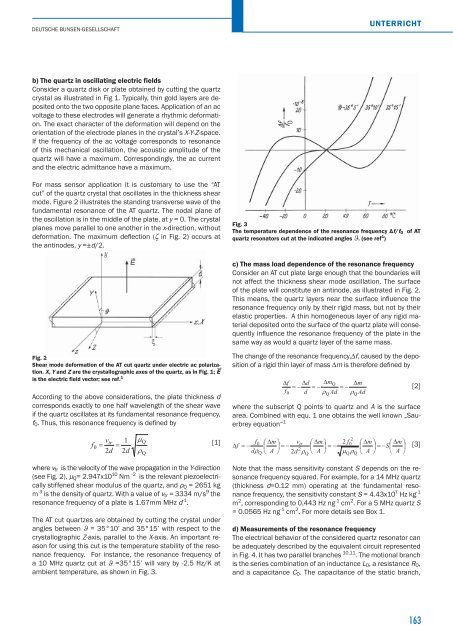
b) The quartz in oscillating electric fields<br />
Consider a quartz disk or plate obtained by cutting the quartz<br />
crystal as illustrated in Fig 1. Typically, thin gold layers are deposited<br />
onto the two opposite plane faces. Application of an ac<br />
voltage to these electrodes will generate a rhythmic deformation.<br />
The exact character of the deformation will depend on the<br />
orientation of the electrode planes in the crystal’s X-Y-Z-space.<br />
If the frequency of the ac voltage corresponds to resonance<br />
of this mechanical oscillation, the acoustic amplitude of the<br />
quartz will have a maximum. Correspondingly, the ac current<br />
and the electric admittance have a maximum.<br />
For mass sensor application it is customary to use the “AT<br />
cut” of the quartz crystal that oscillates in the thickness shear<br />
mode. Figure 2 illustrates the standing transverse wave of the<br />
fundamental resonance of the AT quartz. The nodal plane of<br />
the oscillation is in the middle of the plate, at y = 0. The crystal<br />
planes move parallel to one another in the x-direction, without<br />
deformation. The maximum defl ection (ζ in Fig. 2) occurs at<br />
the antinodes, y =±d/2.<br />
Fig. 2<br />
Shear mode deformation of the AT cut quartz under electric ac polariza-<br />
→<br />
tion. X, Y and Z are the crystallographic axes of the quartz, as in Fig. 1; E<br />
is the electric field vector; see ref. 1<br />
According to the above considerations, the plate thickness d<br />
corresponds exactly to one half wavelength of the shear wave<br />
if the quartz oscillates at its fundamental resonance frequency,<br />
f0. Thus, this resonance frequency is defi ned by<br />
f<br />
0<br />
UNTERRICHT<br />
v 1 �<br />
2<br />
tr Q<br />
[1]<br />
f<br />
� �<br />
0 � �m<br />
� vtr<br />
� �m<br />
� 2 f0<br />
� �m<br />
� � �m<br />
�<br />
�f<br />
� � � � � � � � � � � � � �S�<br />
�<br />
2d 2d<br />
�<br />
d�<br />
� A<br />
2<br />
� 2d � � A � � � � A � � A �<br />
where vtr is the velocity of the wave propagation in the Y-direction<br />
(see Fig. 2), μQ= 2.947x10 10 Nm -2 is the relevant piezoelectrically<br />
stiffened shear modulus of the quartz, and ρQ = 2651 kg<br />
m -3 is the density of quartz. With a value of vtr = 3334 m/s 9 the<br />
resonance frequency of a plate is 1.67mm MHz d -1 .<br />
The AT cut quartzes are obtained by cutting the crystal under<br />
angles between ϑ = 35°10’ and 35°15’ with respect to the<br />
crystallographic Z-axis, parallel to the X-axis. An important reason<br />
for using this cut is the temperature stability of the resonance<br />
frequency. For instance, the resonance frequency of<br />
a 10 MHz quartz cut at ϑ =35°15’ will vary by -2.5 Hz/K at<br />
ambient temperature, as shown in Fig. 3.<br />
Q<br />
Fig. 3<br />
The temperature dependence of the resonance frequency Δf/f0 of AT<br />
quartz resonators cut at the indicated angles ϑ. (see ref 1 )<br />
c) The mass load dependence of the resonance frequency<br />
Consider an AT cut plate large enough that the boundaries will<br />
not affect the thickness shear mode oscillation. The surface<br />
of the plate will constitute an antinode, as illustrated in Fig. 2.<br />
This means, the quartz layers near the surface infl uence the<br />
resonance frequency only by their rigid mass, but not by their<br />
elastic properties. A thin homogeneous layer of any rigid material<br />
deposited onto the surface of the quartz plate will consequently<br />
infl uence the resonance frequency of the plate in the<br />
same way as would a quartz layer of the same mass.<br />
The change of the resonance frequency,∆f, caused by the deposition<br />
of a rigid thin layer of mass ∆m is therefore defi ned by<br />
where the subscript Q points to quartz and A is the surface<br />
area. Combined with equ. 1 one obtains the well known „Sauerbrey<br />
equation“ 1<br />
Q<br />
�f<br />
f<br />
0<br />
�d<br />
�mQ<br />
�m<br />
� � � � � � �<br />
d � Ad � Ad<br />
Q<br />
Q<br />
Note that the mass sensitivity constant S depends on the resonance<br />
frequency squared. For example, for a 14 MHz quartz<br />
(thickness d=0.12 mm) operating at the fundamental resonance<br />
frequency, the sensitivity constant S = 4.43x10 7 Hz kg -1<br />
m 2 , corresponding to 0.443 Hz ng -1 cm 2 . For a 5 MHz quartz S<br />
= 0.0565 Hz ng -1 cm 2 . For more details see Box 1.<br />
d) Measurements of the resonance frequency<br />
The electrical behavior of the considered quartz resonator can<br />
be adequately described by the equivalent circuit represented<br />
in Fig. 4. It has two parallel branches 10,11 . The motional branch<br />
is the series combination of an inductance L0, a resistance R0,<br />
and a capacitance C0. The capacitance of the static branch,<br />
Q<br />
Q<br />
Q<br />
[2]<br />
[3]<br />
163