bunsenmagazin - Deutsche Bunsengesellschaft für Physikalische ...
bunsenmagazin - Deutsche Bunsengesellschaft für Physikalische ...
bunsenmagazin - Deutsche Bunsengesellschaft für Physikalische ...

Sie wollen auch ein ePaper? Erhöhen Sie die Reichweite Ihrer Titel.
YUMPU macht aus Druck-PDFs automatisch weboptimierte ePaper, die Google liebt.
UNTERRICHT<br />
172<br />
THE IMPEDANCE ANALYSIS<br />
The electric energy supplied to the quartz oscillator forces the<br />
quartz to do mechanical work. It is therefore clear that the<br />
electric behavior of the quartz oscillator is closely related to<br />
the material constants and the dimensions of the quartz plate.<br />
For the parameters R0, L0, C0, and C * of the equivalent circuit<br />
(Fig. 4) one fi nds at the fundamental resonance frequency (see<br />
Arnau and Soares 11 ):<br />
[10]<br />
Here, A is the active area of the quartz, i.e. the area of the<br />
metal electrodes, and d is the plate thickness. The following<br />
values apply for an AT-cut quartz 11 :<br />
ε22 = 3.982x10 -11 A 2 s 4 Kg -1 m -3 (permittivity)<br />
ηQ = 9.27x10 -3 Pa s (effective viscosity)<br />
ηQ = 2.947x10 10 N m -2 (piezoelectrically stiffened shear modulus)<br />
e26 = 9.657x10 -2 A s m -2 (piezoelectric constant)<br />
ρQ = 2651 Kg m -3 (density).<br />
A 5 MHz AT quartz has a thickness of d = 3.34x10⁻⁴ m (see<br />
equ.1). With electrodes of diameter 6 mm (A = 2.83x10⁻⁵ m2 )<br />
one obtains R0 = 14.5 Ω, L0 = 0.0468 H, C0 = 2.17x10⁻¹⁴ F,<br />
and C * = 3.37x10⁻¹² F. In practical work on has to consider that<br />
the capacitances of the connecting wires and of the measuring<br />
instrument contribute to C * . To present a realistic picture, the<br />
admittance of the 5 MHz quartz represented in Fig. 5a/b was<br />
calculated with a value of C * = 40 pF instead of the oscillator’s<br />
intrinsic C * value.<br />
As shown in Fig. 5, one is normally interested in the behavior<br />
of the oscillator over a narrow frequency range near resonance.<br />
Consider the role of the parallel capacitance C * on<br />
the Y{Im}-f curve in this frequency range. According to eq. 4,<br />
C * contributes to the Y{Im}-f curve a nearly constant value of<br />
Y{Im}=ωC * , i.e. C * causes the curve to shift almost parallel to<br />
more positive values. In Fig. 21 the Y{Im}-f curve (a) is calculated<br />
for the quartz in vacuum, as in Fig. 5a, but with C * = 0. The<br />
comparison between the Y{Im}-f curves of Figs. 5a and 21 (a)<br />
illustrates that it is the upward shift caused by C * that leads<br />
to the second frequency at which Y{Im}=0, defi ning the second<br />
resonance frequency, fp.<br />
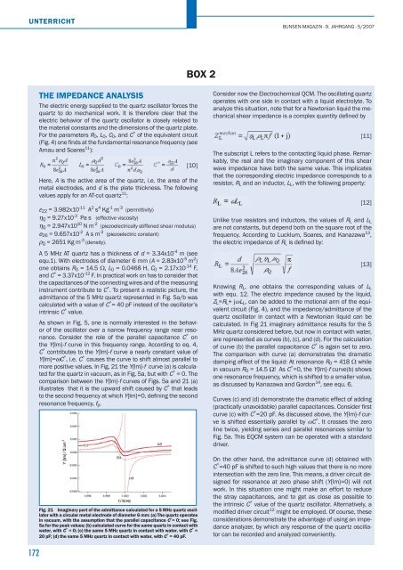
Fig. 21 Imaginary part of the admittance calculated for a 5 MHz quartz oscillator<br />
with a circular metal electrode of diameter 6 mm: (a) The quartz operates<br />
in vacuum, with the assumption that the parallel capacitance C * = 0; see Fig.<br />
5a for the peak values; (b) calculated curve for the same quartz in contact with<br />
water, with C * = 0; (c) the same 5 MHz quartz in contact with water, with C * =<br />
20 pF; (d) the same 5 MHz quartz in contact with water, with C * = 40 pF.<br />
BOX 2<br />
BUNSEN-MAGAZIN · 9. JAHRGANG · 5/2007<br />
Consider now the Electrochemical QCM. The oscillating quartz<br />
operates with one side in contact with a liquid electrolyte. To<br />
analyze this situation, note that for a Newtonian liquid the mechanical<br />
shear impedance is a complex quantity defi ned by<br />
[11]<br />
The subscript L refers to the contacting liquid phase. Remarkably,<br />
the real and the imaginary component of this shear<br />
wave impedance have both the same value. This implicates<br />
that the corresponding electric impedance corresponds to a<br />
resistor, RL and an inductor, LL, with the following property:<br />
[12]<br />
Unlike true resistors and inductors, the values of RL and LL<br />
are not constants, but depend both on the square root of the<br />
frequency. According to Lucklum, Soares, and Kanazawa 13 ,<br />
the electric impedance of RL is defi ned by:<br />
[13]<br />
Knowing RL, one obtains the corresponding values of LL<br />
with equ. 12. The electric impedance caused by the liquid,<br />
ZL=RL+ jωLL, can be added to the motional arm of the equivalent<br />
circuit (Fig. 4), and the impedance/admittance of the<br />
quartz oscillator in contact with a Newtonian liquid can be<br />
calculated. In Fig 21 imaginary admittance results for the 5<br />
MHz quartz considered before, but now in contact with water,<br />
are represented as curves (b), (c), and (d). For the calculation<br />
of curve (b) the parallel capacitance C * is again set to zero.<br />
The comparison with curve (a) demonstrates the dramatic<br />
damping effect of the liquid: At resonance R0 = 418 Ω while<br />
in vacuum R0 = 14.5 Ω! As C * =0, the Y{Im}-f curve(b) shows<br />
one resonance frequency, which is shifted to a smaller value,<br />
as discussed by Kanazawa and Gordon 14 , see equ. 6.<br />
Curves (c) and (d) demonstrate the dramatic effect of adding<br />
(practically unavoidable) parallel capacitances. Consider fi rst<br />
curve (c) with C * =20 pF. As discussed above, the Y{Im}-f curve<br />
is shifted essentially parallel by ωC * . It crosses the zero<br />
line twice, yielding series and parallel resonances similar to<br />
Fig. 5a. This EQCM system can be operated with a standard<br />
driver.<br />
On the other hand, the admittance curve (d) obtained with<br />
C * =40 pF is shifted to such high values that there is no more<br />
intersection with the zero line. This means, a driver circuit designed<br />
for resonance at zero phase shift (Y{Im}=0) will not<br />
work. In this situation one might make an effort to reduce<br />
the stray capacitances, and to get as close as possible to<br />
the intrinsic C * value of the quartz oscillator. Alternatively, a<br />
modifi ed driver circuit 12 might be employed. Of course, these<br />
considerations demonstrate the advantage of using an impedance<br />
analyzer, by which any response of the quartz oscillator<br />
can be recorded and analyzed conveniently.