- Page 2 and 3:
DOE-2:ENGINEERS MP.NUAL .( Versi on
- Page 8 and 9:
ABSTRACT •...... ACKNOWLEDGMENTS
- Page 10 and 11:
TABLE OF CONTENTS (Cont.) Page 2.3.
- Page 12:
TABLE OF CONTENTS (Cont.) III. LOAD
- Page 15 and 16:
TABLE OF CONTENTS (Cont). 2.2 Equip
- Page 17:
2.3 TABLE OF CONTENTS (Cont.) Page
- Page 20:
ABSTRACT ••....• ACKNOWLEDGME
- Page 24 and 25:
ACK NOWLE DGMENTS This Engineers Ma
- Page 26 and 27:
DOE-2 STAFF PERSONNEL Principal Inv
- Page 28 and 29:
STATUS - MAY 1981 This edition of t
- Page 30:
SERVICE BUREAU MISSOURI McDonnell-D
- Page 35 and 36:
1.4 Volume IV - Engineers Manual Th
- Page 41 and 42:
4. CHAPTER I REFERENCES 1. D. A. Yo
- Page 43 and 44:
2.4 TABLE OF CONTENTS (Cont.) 2.3.4
- Page 45:
3. CURVE FIT. 4. CHAPTER II REFEREN
- Page 61:
These are the fundamental equations
- Page 66:
1.2 Outline of Algorithm Step 1 Let
- Page 70:
1.3 Description of the Subroutines
- Page 75 and 76:
2. WEIGHTING FACTORS by J. F. Kerri
- Page 77:
can be selected for use in 00E-2. T
- Page 93:
t o 0.1 0.2 0.3 0.4 0.5 0.6 0.7 0.8
- Page 98 and 99:
In terms of Laplace transfer functi
- Page 100 and 101:
This infin ite sequence can be ch a
- Page 102 and 103:
The total energy in the pulse is no
- Page 105:
the outside air temperature, and Kv
- Page 112:
calculated from the wall response f
- Page 117:
This is the basis of the air-temper
- Page 129 and 130:
TABLE 11.6 LIGHTING DATA FOR WEIGHT
- Page 131 and 132:
In the sketch, Rc is the convective
- Page 135:
R' ! Ts Os Circuit A ROO 1 Circuit
- Page 141 and 142:
I -'- I + DOE-2 Values -- This Corr
- Page 143 and 144:
2.4. Weighting-Factor Subroutines i
- Page 146 and 147:
18. Count number of delayed surface
- Page 149 and 150:
4. Increment surface counter and in
- Page 151:
emainder, 0.4, to the other walls a
- Page 154:
2.4.S Subroutine WFMATG 2.4.8.1 Sum
- Page 157:
The \/0 \/1 \/2 - d1 WJ. - d(jl2 =
- Page 160:
N WFDDT = L Xi Y i' i=1 where N is
- Page 163 and 164:
TABLE 11.10 (Cant. ) Section II.2.3
- Page 165 and 166:
Program Variable FLRFUR FLRWT FR FR
- Page 167 and 168: Program Var iab 1e PFA QFLOOR QSi Q
- Page 173: has been simplified to ZX, etc. The
- Page 178 and 179: 5. CHAPTER II INDEX (Cont.)* Duhame
- Page 180 and 181: 5. CHAPTER II INDEX (Cont.)* solar.
- Page 182: III. LOADS SIMULATOR TABLE OF CONTE
- Page 187 and 188: 1.2 LOADS Relationship to the Rest
- Page 189 and 190: Within the space loop, but outside
- Page 199 and 200: 2.2 Weather 2.2.1 Weather V ariab l
- Page 201: 1061 = the enthalpy of saturated wa
- Page 204: 2 • 3. So 1 ar Cal cu 1 at ion s
- Page 208: The diffuse radiation for cloudy co
- Page 211 and 212: Step 2 In Eq. (IIL8) the hour angle
- Page 213 and 214: Step 6 10) , where Equation (IILI0)
- Page 215 and 216: The clear sky value is then reduced
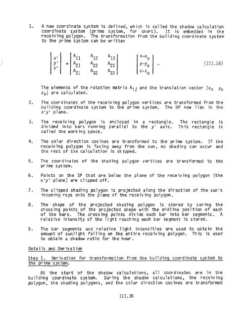
- Page 220: into a new system called the shadow
- Page 223 and 224: y' (A, Bo) Fig. II!.l3. Establishin
- Page 229 and 230: Breakdown by Subroutine Steps 1 thr
- Page 231: The fraction of the overhead light
- Page 235: 9. If the user has input an overhea
- Page 238 and 239: QPPS QPPL QEQPS2 QEQPL2 QZEQEL QELE
- Page 241 and 242: is divided among the room surfaces.
- Page 243 and 244: 1 stucco, 2 brick and rough plaster
- Page 245: Program Variab le T SOLI DBTR GAMM
- Page 254 and 255: Program Var iab le k XSAREA Descr i
- Page 256: TABLE 111.5 COEFFICIENTS OF TRANSMI
- Page 260 and 261: Step 3 The formula for outside film
- Page 262 and 263: Program Var iab 1e TDIF ADIFO ADIRI
- Page 265 and 266: SOLID = DDIF + RDIR (1 - DRGOLGE),
- Page 267 and 268:
Program Var iab le RDNCC RAYCOS( 1)
- Page 269:
2.8 Infiltration Infiltration is on
- Page 276:
15. M. Rubin, "Solar Optical Proper
- Page 279 and 280:
4. CHAPTER III INDEX (Cont.)* film,
- Page 281 and 282:
4. CHAPTER III INDEX (Cont.)* shadi
- Page 284 and 285:
4. CHAPTER III INDEX (Cont.)* weigh
- Page 286 and 287:
TABLE OF CONTENTS (Cont.) 3.2.3 Pac
- Page 288:
assuming a steady state solution of
- Page 294:
z z Fig. IV.2. Linear equation. Fig
- Page 301 and 302:
For direct expansion packaged equip
- Page 303 and 304:
For gas and oil furnaces, the energ
- Page 305 and 306:
1.4 Interactions of Equipment Contr
- Page 309 and 310:
1.5 Design Calculations As describe
- Page 311:
2. DESIGN CALCULATIONS (Subroutine
- Page 317 and 318:
ecause it approximates, or equals,
- Page 319:
If no value has been specified for
- Page 322 and 323:
peak heating load. If the user has
- Page 326 and 327:
WC = (CBF * WM) + [(1.0 - CBF) * WS
- Page 328 and 329:
TCZ D = ESIGN-CDOL-T - CONS(l) *
- Page 331:
(9 ) where nzones OLMAX; L nz;l «O
- Page 336 and 337:
The sensible cool ing component is
- Page 338 and 339:
CFMRM MIN-CFM-RATIOsystem = SUPPLY-
- Page 341 and 342:
and the maximum heating (heat addit
- Page 343 and 344:
cal cul ated. If th i sis not true,
- Page 345:
where RETRnz and latent heat gain,
- Page 348:
3.1.2. Single-Duct Air-Handler Simu
- Page 352 and 353:
This is the supply air humidity rat
- Page 357:
The moisture removal (in lbs. H20)
- Page 361:
3.1.3 Dual-Duct System Simulation f
- Page 364:
If the net heating/cooling rate is
- Page 371:
OW WR = HUM RAT + F + PO If the amo
- Page 374 and 375:
A + B weOLM; e ' where A; CBF * [(F
- Page 376:
H = the enthalpy of air at the cond
- Page 382 and 383:
Then, ZQH : ZQHR + . If the zone is
- Page 384:
nzones QHB = L QHBZ * MULTIPLIER ,
- Page 387 and 388:
3.1.6 Heating and Ventilating Syste
- Page 389:
The quantities ZQH and are negativ
- Page 393:
By combining Eq. (IV.290) and Eq. (
- Page 396 and 397:
3.1.7 Induction Systems Simulation
- Page 398 and 399:
and THMAXZ = TL - CONS(l) * * HON
- Page 400:
nzones QCZ = L ZQC nz * MULTIPLIER
- Page 403 and 404:
3.1.8 Residential System (subroutin
- Page 405 and 406:
T = the larger of DBT and COOL-FT-M
- Page 407 and 408:
Equation (IV.340) presents the tran
- Page 411:
SH SL RH RL DBT = SUPPLY-HI = SUPPL
- Page 417 and 418:
infiltration air flow rate, nzones
- Page 420:
QCLAT = (WM - WCOIL) * CONS(2) * SU
- Page 424 and 425:
3.2 Unitary Systems 3.2.1 Fan Coil
- Page 427 and 428:
B. Calculate the hourly zone temper
- Page 429:
3.2.2. Water-to-Air California Heat
- Page 436:
and by reapplying Eqs. (IV.428) and
- Page 439 and 440:
QH = (FTEMP - MIN-FLUID-T) * FLUID-
- Page 441:
OA-CHANGES * PO = the larger of 60
- Page 445 and 446:
where CBF = COIL-BF * CVAL(COIL-BF-
- Page 447 and 448:
(IV.473) and by reapplying Eqs. (IV
- Page 450 and 451:
where PLRH - QHP + QD (assuming the
- Page 452:
TCMINZ = DBT + SUPPLY-OELTA-T = CO
- Page 456 and 457:
3.2.5. Panel Heating (subroutine PA
- Page 458 and 459:
3.3 Special System - The Summation
- Page 461:
where, (HENOW- - - - TRY)] + [GI
- Page 466 and 467:
Step 3. Correct the Heat Extraction
- Page 468:
is the maximum air flow rate for he
- Page 471 and 472:
HENOW = [CONS(I) * ACFM * «TNOW>-T
- Page 473:
where FFUEL = CAP * FURNACE-HIR * C
- Page 476:
In both these cases (fans running t
- Page 480 and 481:
MIN-SUPPLY-T is the lowest possible
- Page 483:
The equation that relates the zone
- Page 486 and 487:
WM = (POMIN * HUMRAT) + [(1.0 - POM
- Page 488 and 489:
HEATING-CAPACITY is the total, or r
- Page 490 and 491:
C. Note that the average zone tempe
- Page 493 and 494:
The mixed air temperature (TM) is t
- Page 495 and 496:
where FAN-CONTROL specifies the fan
- Page 497:
4.6 Calculation of Wet-Bulb Tempera
- Page 500:
TABLE IV.4 INTERPOLATION TABLE FOR
- Page 504:
6. CHAPTER IV 1NDEX* (Cont.) ceilin
- Page 507 and 508:
6. CHAPTER I V INOEX* (Cont.) dual
- Page 510 and 511:
6. CHAPTER IV INDEX* (Cont.) four p
- Page 512:
6. CHAPTER IV INDEX* (Cont.) heatin
- Page 515 and 516:
6. CHAPTER IV INDEX* (Cant.) multiz
- Page 517 and 518:
6. CHAPTER IV INDEX* (Cont.) packag
- Page 519 and 520:
6. CHAPTER IV INDEX* (Cant.) packag
- Page 521 and 522:
6. CHAPTER IV INDEX* (Cont.) packag
- Page 523:
6. CHAPTER IV INOEX* (Cont.) reside
- Page 527:
6. CHAPTER IV INDEX* (Cont.) supply
- Page 530 and 531:
6. CHAPTER IV INDEX* (Cont.) unit h
- Page 532 and 533:
6. CHAPTER IV INDEX* (Cont.) variab
- Page 534 and 535:
v. PLANT SIMULATOR TABLE OF CONTENT
- Page 536 and 537:
2.3 TABLE OF CONTENTS (Cont.) Page
- Page 538 and 539:
1. PLANT OVERVIEW by Steven D. Gate
- Page 540 and 541:
a. Preheat (Note: solar). coil, mai
- Page 542 and 543:
In summary, it is up to the user to
- Page 544:
Keywords [*J-EIR-FPLR FORTRAN V ar
- Page 547 and 548:
,... c: ., ·u :;: -w PLR Fig. V.2
- Page 549 and 550:
2.2 Equipment Algorithms This secti
- Page 551 and 552:
If the steam pressure is not input
- Page 553 and 554:
percent efficient and would normall
- Page 555 and 556:
Keywords E-STM-BOILER-LOSS E-HW-BOI
- Page 557 and 558:
Input Required Heating PLANT-PARAME
- Page 559 and 560:
makeup water temperature. It is ass
- Page 561:
Input Hot Water Heating Required SI
- Page 564:
the chillers, both capacity and ene
- Page 567 and 568:
Keyword Mm-RATIO DBUN-HT - REC-RAT
- Page 570 and 571:
Algorithm Description Capaci ty adj
- Page 572 and 573:
Electrical energy consumption - The
- Page 574:
In the direct cooling mode, RCAP; i
- Page 577 and 578:
SIZE MAX-NUMBER-AVAIL Economic Data
- Page 579 and 580:
where TREC is the leaving condenser
- Page 581:
EIRI = fl{CHWT,ECT = TOES) ELEG = C
- Page 586:
Keyword TWR-WTR SET-POINT FORTRAN
- Page 589 and 590:
If NCELL is greater than MAX-NUMBER
- Page 592 and 593:
Rating factor Fr - The curves used
- Page 594:
was developed. This can be rearrang
- Page 599 and 600:
There are several variables that ar
- Page 602 and 603:
Step 3. The range (temperature drop
- Page 604 and 605:
ARCELL * MAX-NUMBER-AVAIL RF = GPM
- Page 606 and 607:
3. us ing the hot tank to store exc
- Page 608 and 609:
Keyword HEAT-SUPPLY RATE HTANK-EN
- Page 610 and 611:
simulates the supply and demand lin
- Page 614 and 615:
the EQDEM array is simply a record
- Page 616 and 617:
2.2.5.1 Design Calculations (subrou
- Page 618 and 619:
algorithm, although they are discus
- Page 620 and 621:
HTGAVE19 corresponding to the stora
- Page 622 and 623:
The water flow rate through the spa
- Page 624 and 625:
FORTRAN Engineering Keywords Variab
- Page 628 and 629:
where EELEC is the electrical load
- Page 630 and 631:
FORTRAN Engineering Keyword Variabl
- Page 632 and 633:
Keyword FORTRAN Engineering Variabl
- Page 635:
2.2.8.1 User Defined Equipment Oper
- Page 641 and 642:
3. There are both absorption and co
- Page 643 and 644:
where E1Rcomp is the electric input
- Page 645:
Step 3. Free Cooling. If the genera
- Page 648 and 649:
or where CCOMP * RELCOM * RHTGEN =
- Page 650:
CAPC2 is the design capacity of the
- Page 653 and 654:
Step 21. Recalculate the steam turb
- Page 655 and 656:
Step 4. If there are no gas turbine
- Page 657 and 658:
TABLE V.I EXAMPLE OF EQUIPMENT COMB
- Page 659 and 660:
Keywords LABOR MIN-MONTHL Y-CHG MIN
- Page 662 and 663:
Keywords PROJECT-LIFE BLOCK MIN-PEA
- Page 664 and 665:
and FAL FL * (1 e - FL ) = 1 FL (1
- Page 668 and 669:
Step 2 The number of cycles in the
- Page 670 and 671:
Step 2 is If a uniform cost appl ie
- Page 672 and 673:
Step 7 The yearly charges for each
- Page 674 and 675:
5. CHAPTER V INDEX (for non-solar e
- Page 676 and 677:
5. CHAPTER V INDEX (for non-solar e
- Page 678 and 679:
S. CHAPTER V INDEX (for non-solar e
- Page 680:
VI. ECONOMICS SIMULATOR TABLE OF CO
- Page 683:
These quantities are calculated by
- Page 690 and 691:
1.4.6 Major overhaul cost Major ove
- Page 693:
1.5.3 Total life-cycle cost savings
- Page 697:
I 2. CHAPTER VI REFERENCES 1. "Li f
- Page 706:
, DAYLIGHTING CALCULATION IN DOE-2
- Page 712:
(a) light from sky passes through w
- Page 715:
2.3 Daylight Factors The following
- Page 719 and 720:
Sun height' 60° Sun height' 80° F
- Page 723 and 724:
Table 3 Monthlx Average AtmosE:herl
- Page 725:
Table 4 Monthll Average AtmoBE:heri
- Page 742 and 743:
Table 6 Recommended Maximum Dayligh
- Page 744 and 745:
7. Calculate daylight factors. The
- Page 748:
( 3) Construct unit vector along ra
- Page 752:
i. End of Sun Azimuth LooE. j. End


