DOMINO Panel Formwork - Peri
DOMINO Panel Formwork - Peri
DOMINO Panel Formwork - Peri

You also want an ePaper? Increase the reach of your titles
YUMPU automatically turns print PDFs into web optimized ePapers that Google loves.
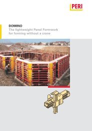
<strong>DOMINO</strong> <strong>Panel</strong> <strong>Formwork</strong><br />
Introduction<br />
Standard configuration<br />
General<br />
The <strong>DOMINO</strong> wall formwork system<br />
consists of lightweight panel formwork<br />
for housing and civil engineering (foundations)<br />
projects with panels made of<br />
steel or aluminium.<br />
The basic equipment includes panel,<br />
corner and stopend elements as well as<br />
length compensation and scaffold<br />
brackets. For element connections, the<br />
alignment coupler or wedge clamp as<br />
well as the compensation waler are<br />
used, along with a range of additional<br />
parts required to carry out forming.<br />
Due to the integrated tie points, the<br />
panels can be used in both a vertical<br />
and horizontal position.<br />
The panels can be extended in 25 cm<br />
increments.<br />
Steel components are red powder-coated,<br />
aluminium elements are in yellow.<br />
Intended use<br />
1. PERI products are exclusively technical<br />
working materials which are intended<br />
for commercial use by technically<br />
competent users only.<br />
2. These assembly instructions serve as<br />
the basis for the project-related risk assessment<br />
and the instructions for the<br />
provision and use of the system by the<br />
contractor (user). However, they do not<br />
replace these.<br />
3. Only PERI original components may<br />
be used. The use of other products and<br />
spare parts represents a misapplication<br />
with associated safety risks.<br />
Steel panels h = 2.50 m<br />
– 3 panel heights and 4 panel widths<br />
– Permissible fresh concrete pressure:<br />
for concreting heights up to 2.50 m,<br />
withstands full hydrostatic pressure<br />
according to DIN 18202, Table 3, Line 7.<br />
For greater heights, a fresh concrete<br />
pressure of 60 kN/m² is permissible,<br />
Line 6.<br />
Aluminium panels h = 2.50 m<br />
– 2 panel heights and 2 panel widths<br />
– Permissible fresh concrete pressure:<br />
for concreting heights up to 2.50 m,<br />
withstands full hydrostatic pressure<br />
according to DIN 18202, Table 3, Line 6.<br />
For greater heights, a fresh concrete<br />
pressure of 50 kN/m² is permissible,<br />
Line 5.<br />
4. The components are to be inspected<br />
before each use to ensure that they are<br />
in perfect condition and function correctly.<br />
5. Changes to PERI components are<br />
not permissible and represent a misapplication<br />
with associated safety risks.<br />
6. Safety instructions and permissible<br />
loads must be observed at all times.<br />
7. Components provided by the contractor<br />
must conform with the characteristics<br />
required in these assembly instructions<br />
as well as all valid construction<br />
guidelines and standards.<br />
Steel panel h = 2.75 m<br />
– 3 panel heights and 4 panel widths<br />
– Permissible fresh concrete pressure:<br />
for concreting heights up to 2.75 m,<br />
withstands full hydrostatic pressure<br />
according to DIN 18202,Table 3, Line 6.<br />
Aluminium panel h = 2.75 m<br />
– 2 panel heights and 1 panel width<br />
– Permissible fresh concrete pressure:<br />
for concreting heights up to 2.75 m,<br />
withstands full hydrostatic pressure<br />
according to DIN 18202, Table 3, Line 6.<br />
Steel panel h = 3.00 m<br />
– 3 panel heights and 4 panel widths<br />
– Permissible fresh concrete pressure:<br />
60 kN/m² for concreting heights up to<br />
3.0 m according to DIN 18202,Table 3,<br />
Line 6.<br />
In particular, the following apply if nothing<br />
else is specified:<br />
– timber components: Strength Class<br />
C24 for Solid Wood EN 338.<br />
– scaffold tubes: galvanised steel tubing<br />
with minimum dimensions Ø 48.3<br />
x 3.2 mm according to EN 12811-<br />
1:2003 4.2.1.2.<br />
– scaffold tube couplings according to<br />
EN 74.<br />
8. Deviations from the standard configuration<br />
may only be carried out after a<br />
separate risk assessment has been<br />
done by the contractor (user). On this<br />
basis, appropriate measures for working<br />
safety along with the stability are to<br />
be implemented.<br />
2 Assembly Instructions for Standard Configuration