DOMINO Panel Formwork - Peri
DOMINO Panel Formwork - Peri
DOMINO Panel Formwork - Peri

You also want an ePaper? Increase the reach of your titles
YUMPU automatically turns print PDFs into web optimized ePapers that Google loves.
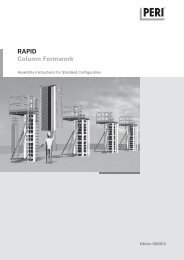
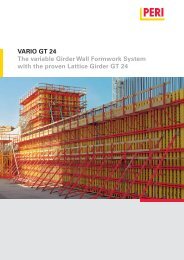
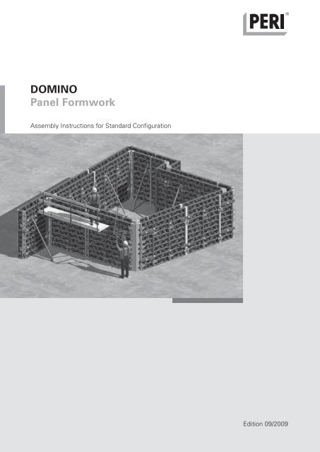
<strong>DOMINO</strong><br />
<strong>Panel</strong> <strong>Formwork</strong><br />
Assembly Instructions for Standard Configuration<br />
Edition 0�/2009
<strong>DOMINO</strong> <strong>Panel</strong> <strong>Formwork</strong><br />
Content<br />
Introduction<br />
Overview, main components 1<br />
Standard configuration 2<br />
Intended use 2<br />
Safety instructions 3<br />
General 3<br />
A General<br />
Basic assembly <strong>DOMINO</strong> 250<br />
A1 Storage and Transportation 4<br />
A2 Maintenance and Cleaning 5<br />
A3 Quick User Guide 6<br />
A4 <strong>DOMINO</strong> 250 <strong>Panel</strong>s 8<br />
A5 <strong>Panel</strong> Connections<br />
Alignment Coupler DRS 10<br />
Compensation Waler DAR 80 11<br />
Wedge Clamp DKS 11<br />
A6 Anchor Point 12<br />
A7 Push-Pull Props 13<br />
A8 Corners<br />
90° corners 14<br />
Articulated Corners 15<br />
135° corners 15<br />
A9 T-junctions<br />
90° T-junction 16<br />
Wall Connection 17<br />
A10 Wall Offset 18<br />
A11 Length Compensation 20<br />
A12 Stopend <strong>Formwork</strong><br />
With timber and filler plywood 21<br />
With Stopend <strong>Panel</strong> MT, MTF 22<br />
A13 Concreting Scaffold<br />
Scaffold Bracket DG 85 24<br />
Guardrails 26<br />
A14 Extensions 27<br />
A15 Foundations 28<br />
A16 <strong>DOMINO</strong> Alu <strong>Panel</strong>s 29<br />
Key<br />
B Basic assembly <strong>DOMINO</strong> 275<br />
B1 <strong>DOMINO</strong> 275 <strong>Panel</strong>s 30<br />
B2 Standard connection 31<br />
90° corners 31<br />
B3 Articulated Corners 32<br />
Stopend <strong>Formwork</strong> 32<br />
B4 Stopend <strong>Panel</strong> MTF 33<br />
B5 Extensions 34<br />
C Basic assembly <strong>DOMINO</strong> 300<br />
C1 <strong>DOMINO</strong> 300 <strong>Panel</strong>s 36<br />
C2 Standard connection 37<br />
90° corners 37<br />
C3 Articulated Corners 38<br />
C4 Stopend <strong>Formwork</strong> 39<br />
Extensions 39<br />
Components<br />
Components 40<br />
Important safety<br />
Instructions Hints Visual Check Tip<br />
Assembly Instructions for Standard Configuration
<strong>DOMINO</strong> <strong>Panel</strong> <strong>Formwork</strong><br />
Introduction<br />
Overview, main components<br />
B5<br />
B2<br />
B5<br />
B1<br />
A4<br />
B4<br />
A3 A1 A2<br />
A1 <strong>Panel</strong><br />
A2 <strong>Panel</strong> connection<br />
A3 Anchor<br />
A4 Push-Pull Props<br />
B1 Corners<br />
B2 T-junctions<br />
B3 Wall offset<br />
B4 Length compensation<br />
B5 Stopend formwork<br />
B6 Working and concreting scaffold<br />
B7 Height extension<br />
1 Assembly Instructions for Standard Configuration<br />
B7<br />
B3<br />
B6
<strong>DOMINO</strong> <strong>Panel</strong> <strong>Formwork</strong><br />
Introduction<br />
Standard configuration<br />
General<br />
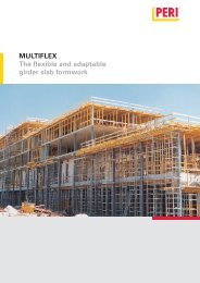
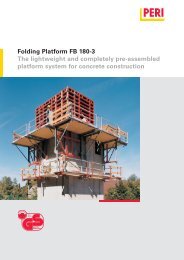
The <strong>DOMINO</strong> wall formwork system<br />
consists of lightweight panel formwork<br />
for housing and civil engineering (foundations)<br />
projects with panels made of<br />
steel or aluminium.<br />
The basic equipment includes panel,<br />
corner and stopend elements as well as<br />
length compensation and scaffold<br />
brackets. For element connections, the<br />
alignment coupler or wedge clamp as<br />
well as the compensation waler are<br />
used, along with a range of additional<br />
parts required to carry out forming.<br />
Due to the integrated tie points, the<br />
panels can be used in both a vertical<br />
and horizontal position.<br />
The panels can be extended in 25 cm<br />
increments.<br />
Steel components are red powder-coated,<br />
aluminium elements are in yellow.<br />
Intended use<br />
1. PERI products are exclusively technical<br />
working materials which are intended<br />
for commercial use by technically<br />
competent users only.<br />
2. These assembly instructions serve as<br />
the basis for the project-related risk assessment<br />
and the instructions for the<br />
provision and use of the system by the<br />
contractor (user). However, they do not<br />
replace these.<br />
3. Only PERI original components may<br />
be used. The use of other products and<br />
spare parts represents a misapplication<br />
with associated safety risks.<br />
Steel panels h = 2.50 m<br />
– 3 panel heights and 4 panel widths<br />
– Permissible fresh concrete pressure:<br />
for concreting heights up to 2.50 m,<br />
withstands full hydrostatic pressure<br />
according to DIN 18202, Table 3, Line 7.<br />
For greater heights, a fresh concrete<br />
pressure of 60 kN/m² is permissible,<br />
Line 6.<br />
Aluminium panels h = 2.50 m<br />
– 2 panel heights and 2 panel widths<br />
– Permissible fresh concrete pressure:<br />
for concreting heights up to 2.50 m,<br />
withstands full hydrostatic pressure<br />
according to DIN 18202, Table 3, Line 6.<br />
For greater heights, a fresh concrete<br />
pressure of 50 kN/m² is permissible,<br />
Line 5.<br />
4. The components are to be inspected<br />
before each use to ensure that they are<br />
in perfect condition and function correctly.<br />
5. Changes to PERI components are<br />
not permissible and represent a misapplication<br />
with associated safety risks.<br />
6. Safety instructions and permissible<br />
loads must be observed at all times.<br />
7. Components provided by the contractor<br />
must conform with the characteristics<br />
required in these assembly instructions<br />
as well as all valid construction<br />
guidelines and standards.<br />
Steel panel h = 2.75 m<br />
– 3 panel heights and 4 panel widths<br />
– Permissible fresh concrete pressure:<br />
for concreting heights up to 2.75 m,<br />
withstands full hydrostatic pressure<br />
according to DIN 18202,Table 3, Line 6.<br />
Aluminium panel h = 2.75 m<br />
– 2 panel heights and 1 panel width<br />
– Permissible fresh concrete pressure:<br />
for concreting heights up to 2.75 m,<br />
withstands full hydrostatic pressure<br />
according to DIN 18202, Table 3, Line 6.<br />
Steel panel h = 3.00 m<br />
– 3 panel heights and 4 panel widths<br />
– Permissible fresh concrete pressure:<br />
60 kN/m² for concreting heights up to<br />
3.0 m according to DIN 18202,Table 3,<br />
Line 6.<br />
In particular, the following apply if nothing<br />
else is specified:<br />
– timber components: Strength Class<br />
C24 for Solid Wood EN 338.<br />
– scaffold tubes: galvanised steel tubing<br />
with minimum dimensions Ø 48.3<br />
x 3.2 mm according to EN 12811-<br />
1:2003 4.2.1.2.<br />
– scaffold tube couplings according to<br />
EN 74.<br />
8. Deviations from the standard configuration<br />
may only be carried out after a<br />
separate risk assessment has been<br />
done by the contractor (user). On this<br />
basis, appropriate measures for working<br />
safety along with the stability are to<br />
be implemented.<br />
2 Assembly Instructions for Standard Configuration
<strong>DOMINO</strong> <strong>Panel</strong> <strong>Formwork</strong><br />
Introduction<br />
Safety instructions<br />
General<br />
1. Deviations for the standard configuration<br />
and/or intended use present a potential<br />
safety risk.<br />
2. All country-specific laws, standards<br />
and other safety regulations are to be<br />
taken into account when our products<br />
are used.<br />
3. During unfavourable weather conditions,<br />
suitable precautions and measures<br />
are to be implemented in order to<br />
guarantee working safety and stability.<br />
4. The contractor (user) must ensure<br />
the stability throughout all phases of<br />
construction. He has to ensure and verify<br />
that all loads which occur are safely<br />
transferred.<br />
5. The contractor (user) has to provide<br />
safe working areas for site personnel<br />
which are to be reached through the<br />
provision of safe access means. Areas<br />
of risk must be cordoned off and clearly<br />
marked. Hatches and openings on accessible<br />
working areas must be kept<br />
closed during working operations.<br />
6. For better comprehensibility, detailed<br />
representations are partly incomplete.<br />
The safety installations which have possibly<br />
not been shown in these detailed<br />
descriptions must nevertheless be<br />
available.<br />
General<br />
Additional PERI product information<br />
– <strong>DOMINO</strong> poster<br />
– Instructions for Use for the <strong>DOMINO</strong><br />
Lifting Hook<br />
– Instructions for Use for pallets and<br />
stacking devices<br />
– PERI design tables<br />
Assembly Instructions for Standard Configuration<br />
Storage and transportation<br />
1. Do not drop the components.<br />
2. Store and transport components so<br />
that no unintentional change in their position<br />
is possible. Detach lifting gear<br />
from the lowered units only if these are<br />
in a stable position and no unimtentional<br />
change is possible.<br />
3. When moving, components are to be<br />
picked up and set down so that any unintentional<br />
toppling over, falling apart,<br />
slipping or rolling are avoided.<br />
4. Use only suitable load-carrying equipment<br />
to move the components as well<br />
as the designated load-bearing points.<br />
5, During lifting and moving procedures,<br />
ensure all loose parts are removed or<br />
secured.<br />
6. During the moving procedure, always<br />
use a guide rope.<br />
7. Move components only on clean, flat<br />
and sufficiently load-bearing surfaces.<br />
System-specific<br />
1. Retract components only when the<br />
concrete has sufficiently hardened and<br />
the person in charge has given the goahead<br />
for striking to take place.<br />
2. Anchoring is to take place only if the<br />
anchorage has sufficient concrete<br />
strength.<br />
The assemblies shown in these PERI<br />
assembly instructions are only examples<br />
which feature only one component<br />
size. They are valid accordingly for all<br />
component sizes contained in the<br />
standard configuration.<br />
3
<strong>DOMINO</strong> <strong>Panel</strong> <strong>Formwork</strong><br />
A1 Storage and Transportation<br />
Instructions for Use for PERI pallets<br />
and stacking devices must always be<br />
taken into consideration.<br />
Manually-created transportation<br />
units must be correctly stacked and<br />
secured.<br />
Transportation<br />
PERI pallets and stacking devices are<br />
suitable for lifting with a crane or forklift.<br />
They can also be moved with the PERI<br />
pallet lifting trolley.<br />
All pallets and stacking devices can be<br />
lifted using both the longitudinal and<br />
front sides.<br />
<strong>DOMINO</strong> Stacking Device<br />
<strong>Panel</strong>s of the same size are to be<br />
transported in stacks.<br />
(Fig. A1.01)<br />
Load-bearing capacity:<br />
500 kg/stacking device = 2.0 t/stack<br />
Number of panels per stack:<br />
2 – 5 <strong>DOMINO</strong> panels of the same size.<br />
Crane sling angle ≤ 45°<br />
4-sling lifting gear L = 3.0 m.<br />
(Fig. A1.02)<br />
Stacking height:<br />
3 stacks, one on top of each other.<br />
Transport of load<br />
Always attach the 4-sling lfting gear<br />
to the four points (1).<br />
(Fig. A1.01)<br />
4<br />
2<br />
1<br />
Fig. A1.01<br />
Fig. A1.02<br />
1<br />
Assembly<br />
1. Place the first panel with the formlining<br />
facing downwards on the rectangular<br />
tube (2). (Fig. A1.02)<br />
2. Insert the second and additional panels<br />
with the formlining facing upwards<br />
in the stacking devices.<br />
(Fig. A1.03)<br />
Fig. A1.03<br />
1<br />
Assembly Instructions for Standard Configuration<br />
1
<strong>DOMINO</strong> <strong>Panel</strong> <strong>Formwork</strong><br />
A2 Maintenance and Cleaning<br />
In order to maintain the value and<br />
operational readiness of the <strong>DOMINO</strong><br />
panel formwork over a long period of<br />
time, the formwork should be carefully<br />
handled at all times.<br />
Maintenance tips<br />
1. Concrete vibrator with rubber end<br />
cap reduces the risk of damage to the<br />
formlining.<br />
2. Spacers used for the reinforcement<br />
with large contact surfaces prevent impressions<br />
forming on the formlining.<br />
3. When placing heavy items on the<br />
formlining, use support timbers in order<br />
to prevent any impressions on and<br />
damage to the formlining surface.<br />
4. Spray the components with PERI Bio<br />
Clean before every use and clean the<br />
rear of the formwork with water immediately<br />
after concreting.<br />
(Fig. A2.01)<br />
5. Spray moving parts, if required, with<br />
PERI Bio Clean.<br />
6. For damage-free transportation, suitable<br />
PERI pallets and stacking devices<br />
are available.<br />
(Fig. A2.02)<br />
Due to the powder coating, cleaning requirements<br />
are kept to a minimum.<br />
Fig. A2.01<br />
Assembly Instructions for Standard Configuration<br />
Fig. A2.02<br />
5
<strong>DOMINO</strong> <strong>Panel</strong> <strong>Formwork</strong><br />
A3 Quick User Guide<br />
Procedures<br />
Primary <strong>Formwork</strong><br />
1. Horizontal assembly.<br />
(Fig. A3.01)<br />
2. Install push-pull props according to<br />
the valid width of influence.<br />
(Abb. A3.02)<br />
3. Transport to place of operations by<br />
crane.<br />
(Fig. A3.03)<br />
Secure panels to prevent tipping as<br />
well as withstanding wind forces.<br />
Release Lifting Hook only when the<br />
push-pull prop has been securely<br />
fixed in position.<br />
Closing formwork with concreting<br />
scaffold<br />
1. Mount brackets to the horizontallypositioned<br />
panel. (Fig. A3.04)<br />
2. Install decking and guardrails.<br />
(Fig. A3.05)<br />
3. Transport to place of operations by<br />
crane.<br />
4. Install anchors.<br />
Release Lifting Hook only after a top<br />
anchor has been installed.<br />
Forming from the external or internal<br />
corner in the direction of the compensation.<br />
6<br />
Fig. A3.01<br />
Fig. A3.03<br />
Fig. A3.04<br />
External corner Internal corner<br />
Fig. A3.02<br />
Fig. A3.05<br />
Assembly Instructions for Standard Configuration
<strong>DOMINO</strong> <strong>Panel</strong> <strong>Formwork</strong><br />
A3 Quick User Guide<br />
Concreting<br />
from safe and secure working scaffold.<br />
(Fig. A3.06)<br />
Striking and moving<br />
from the compensation to the corners.<br />
Concrete strength must be taken into<br />
account.<br />
Secure panels against tipping over<br />
and wind forces.<br />
Release Lifting Hook only when the<br />
push-pull prop has been securely<br />
fixed in position.<br />
Closing formwork<br />
1. Fix lifting hook and attach to crane.<br />
(Fig. A3.07)<br />
2. Remove anchors.<br />
3. Release panel connection.<br />
4. Move element, clean and transport<br />
to place of operations by crane.<br />
5. Connect panel, install anchors.<br />
6. Release crane lifting gear.<br />
Primary formwork<br />
1. Fix lifting hook and attach to crane.<br />
2. Release panel connection.<br />
3. Release push-pull prop anchoring.<br />
4. Move element, clean and transport<br />
to place of operations by crane.<br />
5. Connect panel.<br />
6. Install push-pull props.<br />
7. Release crane lifting gear.<br />
Cleaning<br />
with PERI Bio Clean and PERI spraying<br />
equipment. (Fig. A3.08)<br />
Working scaffold<br />
is not featured<br />
here.<br />
Assembly Instructions for Standard Configuration<br />
Fig. A3.06<br />
Fig. A3.08<br />
Fig. A3.07<br />
7
<strong>DOMINO</strong> <strong>Panel</strong> <strong>Formwork</strong><br />
A4 <strong>DOMINO</strong> 250 <strong>Panel</strong>s<br />
Height [cm]<br />
8<br />
250<br />
125<br />
75<br />
100 75 50<br />
Width [cm]<br />
25 75<br />
DGE<br />
S) A) S) A) S) S) S) A) N) A) A) A)<br />
S) A)<br />
S) A)<br />
Key<br />
S) <strong>Panel</strong>s with steel frames (red powder-coated)<br />
A) <strong>Panel</strong>s with aluminium frames (yellow powder-coated)<br />
N) Standard elements or multi-purpose panels<br />
H) Timber panels<br />
S)<br />
S)<br />
S)<br />
S)<br />
S)<br />
S)<br />
S) A) N)<br />
S) N)<br />
A)<br />
A)<br />
DAW DWD DPA<br />
Assembly Instructions for Standard Configuration<br />
A)<br />
A)<br />
A)<br />
A)<br />
H)<br />
H)
<strong>DOMINO</strong> <strong>Panel</strong> <strong>Formwork</strong><br />
A4 <strong>DOMINO</strong> 250 <strong>Panel</strong>s<br />
<strong>Panel</strong> 250 x 100<br />
10.4<br />
10.5<br />
10.2<br />
(10) <strong>DOMINO</strong> panel<br />
(10.1) Anchor point with tubular rivet<br />
(10.2) <strong>Panel</strong> strut<br />
(10.3) Connecting possibilities for<br />
accessories<br />
(10.4) Transportation holes<br />
(10.5) Openings for moving by hand<br />
(10.6) Frame<br />
(10.7) Formlining<br />
Assembly Instructions for Standard Configuration<br />
10<br />
10.3<br />
10.3<br />
10.6<br />
10.7<br />
10.1<br />
10.3<br />
10.3<br />
10.1<br />
9
<strong>DOMINO</strong> <strong>Panel</strong> <strong>Formwork</strong><br />
A5 <strong>Panel</strong> Connections<br />
Alignment Coupler DRS<br />
Areas of use:<br />
– standard connection<br />
– external corner, internal corner<br />
– obtuse and acute-angled corners<br />
– stopend formwork<br />
– filler timber<br />
– extensions<br />
Number required<br />
2 alignment couplers DRS (20) for<br />
h = 2.50 m on standard connections.<br />
(Fig. A5.01)<br />
Assembly<br />
1. Place wedge (20.1) in upper end position.<br />
2. Open sliding part (20.2).<br />
(Fig. A5.02).<br />
3. Attach Alignment Coupler (20) to<br />
panel strut (10.2).<br />
4. Close sliding part. Continuous adjustment<br />
using the keyway (20.3) possible.<br />
5. Secure wedge. (Fig. A5.03)<br />
The Alignment Coupler is now securely<br />
in position.<br />
If the wedge head (20.4) is up against<br />
the sliding part, there is no clamping effect!<br />
If so, release the wedge, re-position<br />
the sliding part and secure again with<br />
the hammer.<br />
When securing the wedge, the following<br />
effects occur due to the angle of<br />
the frame profile:<br />
1. <strong>Panel</strong>s are flush.<br />
2. <strong>Panel</strong>s are aligned.<br />
3. <strong>Panel</strong>s are tightly connected.<br />
(Fig. A5.03.1)<br />
10<br />
20.3<br />
Fig. A5.02<br />
Fig. A5.03<br />
20<br />
20.2<br />
20.1<br />
20.4<br />
Fig. A5.01<br />
Fig. A5.03.1<br />
3<br />
Assembly Instructions for Standard Configuration<br />
1<br />
20<br />
2
<strong>DOMINO</strong> <strong>Panel</strong> <strong>Formwork</strong><br />
A5 <strong>Panel</strong> Connections<br />
Compensation Waler DAR 80<br />
The Compensation Waler DAR 80 (21)<br />
is used to brace and align panel connections<br />
as well as for transferring forces.<br />
Areas of use:<br />
– length compensation<br />
– corners with double Wall Thickness<br />
Compensator WDA<br />
– acute and obtuse-angled corners<br />
– wall offsets<br />
– stopend formwork<br />
– extensions at great heights<br />
Assembly<br />
1. Insert the hooks into the connecting<br />
holes 10.3 of the panel.<br />
2. Secure wedge.<br />
(Fig. A5.04)<br />
Wedge Clamp DKS<br />
For standard panel joints in the area of<br />
the foundations.<br />
(Fig. A5.05)<br />
Fig. A5.05<br />
Assembly Instructions for Standard Configuration<br />
21<br />
Fig. A5.04<br />
10.3<br />
11
<strong>DOMINO</strong> <strong>Panel</strong> <strong>Formwork</strong><br />
A6 Anchor Point<br />
Anchor System DW 15<br />
Permissible load of the tie rod according<br />
to DIN 18216 is 90 kN.<br />
Components for DW 15<br />
– Tie Rod (30)<br />
– Spacer Tube (31)<br />
– Cone (32)<br />
– Wingnut Pivot Plate (33)<br />
(Fig. A6.01)<br />
Miscellaneous<br />
– Tie Rod Wrench (34) for one-man anchor<br />
point operations from one side<br />
– Plug (35) for sealing tie holes which<br />
are not required.<br />
(Fig. A6.02)<br />
Application<br />
– Use only the required number of ties.<br />
Seal tie holes which are not required.<br />
– Do not exceed permissible tie loads.<br />
– Comply with rate of rise.<br />
– With the use of articulated corners as<br />
90° internal corners, only the outer<br />
drilled holes may be used for anchoring<br />
if using Wingnut Pivot Plates.<br />
(Fig. A6.03)<br />
– If using compensation walers, both<br />
drilled holes can be used for anchoring<br />
e.g. oblique angles.<br />
(Fig. A6.03)<br />
12<br />
30<br />
Fig. A6.01<br />
Fig. A6.02<br />
33 31<br />
34<br />
Fig. A6.03<br />
32<br />
Detail<br />
35<br />
Ø 20 mm<br />
Outer drilled holes<br />
Assembly Instructions for Standard Configuration
<strong>DOMINO</strong> <strong>Panel</strong> <strong>Formwork</strong><br />
A7 Push-Pull Props<br />
Push-Pull Prop Connector<br />
DRA<br />
Assembly<br />
Push-Pull Props and Kicker Braces are<br />
attached to the panels by means of the<br />
Push-Pull Prop Connector DRA (41).<br />
Connections are only possible using the<br />
horizontal panel struts.<br />
(Fig. A7.01)<br />
1. Place the Wedge Closing Device (42)<br />
in a vertical position.<br />
2. Insert the Push-Pull Prop Connector<br />
from below through the connecting<br />
hole.<br />
3. Turn the Wedge Closing Device to a<br />
horizontal position and secure.<br />
Push-Pull Props and Kicker<br />
Braces<br />
1. Attach Push-Pull Prop (40) or Kicker<br />
Brace to the connecting plate (43) using<br />
Pins and Cotter Pins (44).<br />
(Fig. A7.02)<br />
2. Fix base plate, e.g. with PERI Multi<br />
Monti 20 x 130 (45).<br />
(Fig. A7.03)<br />
Permissible push-pull prop spacings<br />
<strong>Formwork</strong> height h<br />
[m]<br />
Max. width of influence<br />
[m]<br />
Actual prop load FRS at maximum<br />
prop spacing<br />
Actual kicker brace load FAV [kN] at<br />
max. prop spacing<br />
distance of base plate [m] from<br />
x =<br />
rear edge of formwork<br />
distance of top connection point<br />
y =<br />
[m] from top of formwork<br />
41<br />
43<br />
2.50 2.75 3.00 4.00 5.00<br />
2.85 2.30 1.82 1.41 1.12<br />
5.0 5.0 5.0 5.0 5.0<br />
2.0 1.5 1.0 1.2 1.1<br />
1.2 1.2 1.2 1.6 2.0<br />
0.5 0.8 1.0 1.2 1.5<br />
Assembly Instructions for Standard Configuration<br />
44<br />
42<br />
41<br />
40<br />
Fig. A7.01 Fig. A7.02<br />
h < 8 m = 0.5 kN/m2 8 m < h < 20 m = 0.8 kN/m2 For the given widths of influence, a maximum force of 11.3 kN<br />
is transferred into the building at the foot of the push-pull<br />
prop.<br />
Perm. F (all directions) Hilti HKD M20 x 80 (B25) 5.8 kN.<br />
Recommended F (all directions) Anchor Bolt MMS 20x130<br />
for concrete<br />
with ß w > 20 N/mm2 11.3 kN<br />
Wind Loads:<br />
If the dynamic pressure deviates from 0.5 kN/m², the<br />
widths of influence can be changed proportionately from<br />
the existing dynamic pressure to 0.5 kN/m².<br />
40<br />
Fig. A7.03<br />
h<br />
43<br />
kN/m 2<br />
0.5<br />
y<br />
FAV<br />
x<br />
FRS<br />
60°<br />
45<br />
13
<strong>DOMINO</strong> <strong>Panel</strong> <strong>Formwork</strong><br />
A8 Corners<br />
90° corners<br />
Wall thicknesses from 20 cm to 36.5 cm<br />
can be continuously formed.<br />
(Fig. A8.01)<br />
– wall thickness 25 cm is without any<br />
adjustment<br />
– for wall thicknesses < 25 cm adjustment<br />
inside<br />
– for wall thicknesses > 25 cm adjustment<br />
outside<br />
Adjustments are carried out by means<br />
of the Wall Thickness Compensator<br />
DWD 5 (18) or timber provided by the<br />
contractor (50).<br />
External corner<br />
Consisting of:<br />
– <strong>Panel</strong> ...x 50 (11)<br />
– Outside Corner Angle DAW (12)<br />
– 2 x Alignment Coupler DRS (20) per<br />
side<br />
(Fig. A8.02)<br />
Internal corner<br />
Consisting of:<br />
– Articulated Corner DGE (13) with Corner<br />
Locking 90° (13.1)<br />
– 2 x Alignment Coupler DRS (20) per<br />
side<br />
(Fig. A8.03)<br />
For the number of Alignment Couplers<br />
required for other panel heights: see<br />
the <strong>DOMINO</strong> poster.<br />
14<br />
50<br />
18<br />
DWD 5<br />
50<br />
Fig. A8.01<br />
Fig. A8.02<br />
20<br />
50<br />
50<br />
30 cm<br />
18<br />
DWD 5<br />
12 11<br />
20<br />
50<br />
18<br />
DWD 5<br />
50<br />
18<br />
2 DWD 5<br />
50<br />
50<br />
24<br />
50<br />
50<br />
35 cm<br />
50<br />
Filler timber 1 cm<br />
18<br />
2 DWD 5<br />
13<br />
13.1<br />
Assembly Instructions for Standard Configuration<br />
50<br />
18<br />
2 DWD 5<br />
Filler timber 1.5 cm<br />
20<br />
50<br />
50<br />
90°<br />
50<br />
25<br />
50<br />
36.5 cm<br />
50<br />
Timber 11.5 cm<br />
50<br />
13.1<br />
Fig. A8.03
<strong>DOMINO</strong> <strong>Panel</strong> <strong>Formwork</strong><br />
A8 Corners<br />
Articulated Corners<br />
For oblique angles of 75° and more.<br />
(Fig. A8.04)<br />
DRS Alignment Couplers are to be installed<br />
in a bottom to top direction for<br />
both external and internal corners.<br />
For the number of Alignment Couplers<br />
required for other panel heights: see<br />
the <strong>DOMINO</strong> poster.<br />
External corner<br />
Consisting of:<br />
5 x Alignment Coupler DRS (20) and<br />
2 x Compensation Waler DAR 80 (23)<br />
for h = 2.50 m. (Fig. A8.04)<br />
Internal corner<br />
Consisting of:<br />
4 x Alignment Coupler DRS (20) for<br />
h = 2.50 m. (Fig. A8.06)<br />
135° corners<br />
For 135° corners, the Positioning Pin<br />
135° (13.1) is used on both the inside<br />
and outside.<br />
(Fig. A8.05)<br />
Assembly of the Locking Pin<br />
1. Remove Corner Locking 90°.<br />
2. Install Positioning Pin 135° with Bolt.<br />
Filler areas (x)<br />
Angle Wall thickness<br />
[cm]<br />
20 25 30 35 36<br />
165° 2.7 3.4 4.1 4.7 4.8<br />
150° 5.6 6.9 8.3 9.6 9.9<br />
135° 8.6 10.7 12.8 14.8 15.2<br />
120° 12 14.9 17.8 20.7 21.2<br />
105° 16 19.8 23.6 27.5 28.2<br />
75° 27.1 33.6 40.1 46.7 48<br />
Fig. A8.04<br />
Fig. A8.06<br />
Assembly Instructions for Standard Configuration<br />
x<br />
13<br />
75<br />
min. 75°<br />
max. 165°<br />
20<br />
75<br />
23<br />
13.1 outside<br />
13.1 inside<br />
x<br />
135°<br />
135°<br />
Fig. A8.05<br />
15
<strong>DOMINO</strong> <strong>Panel</strong> <strong>Formwork</strong><br />
A9 T-junctions<br />
90° T-junctions<br />
Wall thicknesses from 15 cm to 35 cm<br />
can be continuously formed.<br />
(Fig. A9.01)<br />
– wall thickness 25 cm without any adjustment<br />
– for wall thicknesses < 25 cm adjustment<br />
inside<br />
– for wall thicknesses > 25 cm adjustment<br />
outside<br />
Adjustments are carried out by means<br />
of the Wall Thickness Compensator<br />
DWD 5 (18) or timber provided by the<br />
contractor (50).<br />
Assembly<br />
– forming the T-junction with the Articulated<br />
Corner DGE (13)<br />
– form the straight wall section on the<br />
opposite side with <strong>Panel</strong> D 75 (15).<br />
Two compensators (DWD) are required:<br />
install one DWD right and left of the<br />
<strong>Panel</strong> D 75 respectively.<br />
Pilaster<br />
For the arrangement and number of the<br />
horizontal Compensation Walers DAR<br />
80 (24) and Frame Spanner (55):<br />
see Stopend <strong>Formwork</strong> with Timber.<br />
(Fig. A9.02)<br />
16<br />
Fig. A9.01<br />
Fig. A9.02<br />
13<br />
24<br />
15<br />
20<br />
75<br />
25<br />
75<br />
13<br />
55<br />
18<br />
35 36.5<br />
75 75 cm<br />
75 cm<br />
15<br />
Assembly Instructions for Standard Configuration<br />
24<br />
13 13<br />
13 13<br />
13<br />
13<br />
13<br />
15<br />
15<br />
18<br />
13<br />
13<br />
15<br />
15<br />
75<br />
30<br />
75<br />
50<br />
Filler timber 1 cm<br />
13<br />
18<br />
50<br />
Timber 11.5 cm
<strong>DOMINO</strong> <strong>Panel</strong> <strong>Formwork</strong><br />
A9 Wall Connection<br />
Obtuse wall connection<br />
With <strong>DOMINO</strong> <strong>Panel</strong> and Cam Nut<br />
DW 15 (19).<br />
(Fig. A9.03)<br />
With Multi-Purpose <strong>Panel</strong> DM ... x75.<br />
(Fig. A9.04)<br />
With Wall Thickness Compensator<br />
DWD (18) or timber supplied by contractor.<br />
(Fig. A9.05)<br />
Fig. A9.03<br />
Fig. A9.04<br />
Fig. A9.05<br />
Assembly Instructions for Standard Configuration<br />
19<br />
DM 75<br />
DM 75<br />
100 cm<br />
100 cm<br />
18<br />
100 cm<br />
100 cm<br />
100 cm<br />
100 cm<br />
100 cm<br />
100 cm<br />
100 cm<br />
100 cm<br />
17
<strong>DOMINO</strong> <strong>Panel</strong> <strong>Formwork</strong><br />
A10 Wall Offset<br />
Wall offset ≤ 17 cm<br />
By moving the panel laterally.<br />
Consisting of:<br />
– Compensation Waler DAR 80 (21)<br />
– Hook Tie DW 15/400 (29)<br />
– compensation provided by contractor<br />
(50)<br />
– plywood filler at the front (51)<br />
– additional Wedge Clamp DKS (20) for<br />
> 12 cm wall offsets<br />
(Fig. A10.01)<br />
Wall offset 17 – 83 cm<br />
Consisting of:<br />
– Multi-Purpose <strong>Panel</strong> DM 75 (10) (3 cm<br />
increments)<br />
– Articulated Corner DGE (13) internally<br />
and externally<br />
– Compensation Waler DAR 80 (21)<br />
– Stopend Tie DSA (25)<br />
– compensation provided by contractor<br />
(50)<br />
(Fig. A10.02)<br />
Wall offset 25 – 37 cm<br />
Consisting of:<br />
– Articulated Corner DGE (13) internally<br />
and externally<br />
– Outside Corner Angle DAW (12)<br />
– Compensation Waler DAR 80 (21)<br />
– compensation provided by contractor<br />
(50) (maximum 12 cm)<br />
(Fig. A10.03)<br />
Locating board facilitates the positioning<br />
of the formwork panel.<br />
18<br />
Fig. A10.01<br />
Fig. A10.02<br />
Fig. A10.3<br />
13<br />
50 29 20 21<br />
50<br />
12<br />
25<br />
13<br />
≤ 17<br />
21 20<br />
10<br />
≤ 83 cm<br />
25 – 37<br />
21<br />
21<br />
≥ 17<br />
12<br />
51<br />
13<br />
50<br />
29 50<br />
21<br />
10<br />
21<br />
13<br />
25<br />
Assembly Instructions for Standard Configuration
<strong>DOMINO</strong> <strong>Panel</strong> <strong>Formwork</strong><br />
A10 Wall Offset<br />
Height offset<br />
For height offsets: depending on the<br />
offset itself, Alignment Couplers DRS<br />
(20) are installed alternately on the<br />
frame struts of the right and left panels.<br />
(Fig. A10.04)<br />
Fig. A10.04<br />
Assembly Instructions for Standard Configuration<br />
20<br />
20<br />
19
<strong>DOMINO</strong> <strong>Panel</strong> <strong>Formwork</strong><br />
A11 Length Compensation<br />
With timber ≤ 12 cm provided<br />
by the contractor<br />
Length compensation takes place using<br />
timber which has been cut to size (50).<br />
(Fig. A11.01)<br />
– Timber ≤ 10 cm with Alignment Coupler<br />
DRS.<br />
– Timber ≤ 12 cm with Alignment Coupler<br />
DRS and Compensation Waler<br />
DAR 80.<br />
– With compensations > 2.5 cm, anchor<br />
in middle of timber.<br />
– Alignment Couplers DRS (20) are to<br />
arranged as for standard element<br />
joints.<br />
– The Wingnut Pivot Plate DW 15 must<br />
overlap the frame of the adjoining<br />
panel by at least 1 cm<br />
(for timber ≤ 10 cm).<br />
With Filler Support DPA for<br />
compensations up to 30 cm<br />
Consisting of:<br />
– 2 x Filler Support DPA (53)<br />
– plywood filler 21 mm (51)<br />
(Fig. A11.02)<br />
Anchoring must be carried out so that<br />
anchor forces are transferred through<br />
the centre of the PERI Compensation<br />
Waler DAR 80 (21) to the adjacent panels.<br />
20<br />
20<br />
53<br />
max. 10 cm<br />
50<br />
51<br />
Fig. A11.01<br />
Fig. A11.02<br />
21<br />
max. 30 cm<br />
Assembly Instructions for Standard Configuration
<strong>DOMINO</strong> <strong>Panel</strong> <strong>Formwork</strong><br />
A12 Stopend <strong>Formwork</strong><br />
With timber and filler plywood<br />
For wall thicknesses up to 36.5 cm.<br />
Consisting of:<br />
– 3 x Compensation Waler DAR 80 (24)<br />
– 6 x Stopend Tie DSA (25) with Wingnut<br />
Pivot Plate<br />
– 6 x Top Tie Bracket DAH (55) with<br />
Frame Spanner DW 15<br />
(Fig. A12.01)<br />
The fresh concrete pressure from the<br />
Stopend <strong>Formwork</strong> is transferred by<br />
means of the Stopend Tie and Compensation<br />
Waler DAR 80 to the <strong>DOMINO</strong><br />
panels.<br />
24<br />
Fig. A12.01<br />
Assembly Instructions for Standard Configuration<br />
25<br />
55<br />
21
<strong>DOMINO</strong> <strong>Panel</strong> <strong>Formwork</strong><br />
A12 Stopend <strong>Formwork</strong><br />
Stopend panel reinforcement<br />
with and without water<br />
bar<br />
H = 2.50 m and 1.25 m<br />
Consisting of:<br />
– 2 x Outside Pieces AT 3 (56) for approx.<br />
2.5 cm concrete cover or 2 x AT 5 for<br />
approx. 5 cm concrete covering<br />
– 1 x Centre Piece MTF (57)<br />
(Fig. A12.02)<br />
The rubber lip (56.1) allows a continuous<br />
reinforcement thickness of 16 mm.<br />
Assembly without water bar<br />
1. Position primary formwork.<br />
2. Attach Outside Piece AT (56) by<br />
means of Alignment Coupler DRS (20).<br />
3. Install first layer of reinforcement.<br />
4. Place Centre Piece MT (57) in position.<br />
5. Install second layer of reinforcement.<br />
6. Position closing formwork.<br />
7. Install second Outside Piece AT (56)<br />
in Centre Piece MT.<br />
8. Fix with Alignment Coupler DRS (20).<br />
(Fig. A12.03)<br />
22<br />
56.1<br />
Fig. A12.02<br />
20<br />
Fig. A12.03<br />
57 MTF<br />
56 AT<br />
56 57<br />
56.1<br />
16 mm<br />
56 57<br />
MTF<br />
AT<br />
16 mm<br />
DM 75<br />
Concrete cover c:<br />
d - b<br />
c = - Ø<br />
2<br />
c<br />
c<br />
b<br />
c<br />
c<br />
b<br />
DM 75<br />
Reinforcement<br />
d<br />
d<br />
Assembly Instructions for Standard Configuration
<strong>DOMINO</strong> <strong>Panel</strong> <strong>Formwork</strong><br />
A12 Stopend <strong>Formwork</strong><br />
Assembly with water bar<br />
1. Position primary formwork.<br />
2. Attach Outside Piece AT (56) by<br />
means of Alignment Coupler DRS (20).<br />
3. Install first layer of reinforcement.<br />
4. Place Centre Piece MTF (58) in position<br />
and install water bar.<br />
5. Install second layer of reinforcement.<br />
6. Position closing formwork.<br />
7. Install second Outside Piece AT (56)<br />
in Centre Piece MTF.<br />
8. Fix with Alignment Coupler DRS (20).<br />
(Fig. A12.04)<br />
Stopend panel with water<br />
bar<br />
Consisting of:<br />
– 2 x Outside Pieces AT (56)<br />
– 1 x Centre Piece MTF (57)<br />
– 2 x filler plates (51) supplied by the<br />
contractor<br />
56<br />
57<br />
20<br />
51<br />
51<br />
Fig. A12.04<br />
H = 2,50 m<br />
AT 250x3<br />
AT 250x5<br />
H = 1,25 m<br />
AT 125x3<br />
AT 125x5<br />
Assembly Instructions for Standard Configuration<br />
MT 250x20<br />
MT 250x24/25<br />
MT 250x30<br />
MT 250x35/36<br />
MTF 250x20<br />
MTF 250x24/25<br />
MTF 250x30<br />
MTF 250x35/36<br />
MT 125x20<br />
MT 125x24/25<br />
MT 125x30<br />
MT 125x35/36<br />
MTF 125x20<br />
MTF 125x24/25<br />
MTF 125x30<br />
MTF 125x35/36<br />
Wall thickness d [cm]<br />
b<br />
Concrete cover approx. 25 mm Concrete cove approx. 50 mm<br />
[mm] 20 24/25 30 35/36 24/25 30 35/36 40<br />
– 2 2 2 2<br />
– 2 2 2 2<br />
without water bar without water bar<br />
118 1 1<br />
158 1 1<br />
218 1 1<br />
268 1 1<br />
with water bar<br />
with water bar<br />
118 1 1<br />
158 1 1<br />
218 1 1<br />
268 1 1<br />
– 2 2 2 2<br />
– 2 2 2 2<br />
without water bar without water bar<br />
118 1 1<br />
158 1 1<br />
218 1 1<br />
268 1 1<br />
with water bar<br />
with water bar<br />
118 1 1<br />
158 1 1<br />
218 1 1<br />
268 1 1<br />
23
<strong>DOMINO</strong> <strong>Panel</strong> <strong>Formwork</strong><br />
A13 Concreting Scaffold<br />
Scaffold Bracket DG 85<br />
Concreting scaffold is mounted on the<br />
Domino formwork with the Scaffold<br />
Bracket DG 85.<br />
(Fig. A13.01)<br />
Consisting of:<br />
– Scaffold Bracket DG 85 (63)<br />
– Handrail Post HSGP (66)<br />
Permissible load 1.5 kN/m²<br />
Secure planking.<br />
Decking components and guardrails<br />
must be mounted securely in position<br />
at all times.<br />
With extended formwork units, the<br />
working scaffold is mounted as part of<br />
the pre-assembly process.<br />
Permissible bracket spacing in [m]<br />
for scaffolding platform consisting of<br />
wooden planks or boards<br />
Table 8, DIN 4420 Part 1.<br />
Scaffold group Board or plank width Board or plank thickness<br />
24<br />
1, 2, 3<br />
63<br />
3.0 cm 3.5 cm 4.0 cm 4.5 cm 5.0 cm<br />
20 cm 1.25 1.50 1.75 2.25 2.50<br />
24 / 28 cm<br />
1.25 1.75 2.25 2.50 2.75<br />
66<br />
m<br />
2.50<br />
Fig. A13.01<br />
Assembly Instructions for Standard Configuration<br />
m<br />
> 2.00
<strong>DOMINO</strong> <strong>Panel</strong> <strong>Formwork</strong><br />
A13 Concreting Scaffold<br />
Scaffold Bracket DG 85<br />
Assembly<br />
1. Insert Handrail Post HSGP.<br />
2. Slide back fastening bolts (63.1).<br />
3. Hook in Scaffold Brackets (63) in the<br />
connecting holes of the panel and secure<br />
with the fastening bolts.<br />
(Fig. A13.02)<br />
It is possible to use the horizontal panel<br />
struts.<br />
Visual control of the suspension equipment!<br />
4. Install decking planks from below<br />
across the complete bracket width and<br />
then secure.<br />
5. Install guardrails and secure with<br />
nails.<br />
6. Mount end guardrails, e.g. End Handrail<br />
Frame 55 (64).<br />
(Fig. A13.03)<br />
Fig. A13.02<br />
Fig. A13.03<br />
Assembly Instructions for Standard Configuration<br />
64<br />
63<br />
max. prop spacing 2.0 m<br />
max. width of influence 2.0 m<br />
63.1<br />
25
<strong>DOMINO</strong> <strong>Panel</strong> <strong>Formwork</strong><br />
A13 Concreting Scaffold<br />
Guardrails<br />
Consisting of:<br />
– Handrail Post Holder <strong>DOMINO</strong> (65)<br />
– Handrail Post HSGP (66)<br />
(Fig. A13.04)<br />
With a fall-height > 3.0 m, guardrails<br />
are required on the opposite side of the<br />
concreting scaffiold.<br />
Assembly is carried out horizontally. In<br />
cases of vertical assembly use e.g. a<br />
mobile scaffold.<br />
Secure boards with nails!<br />
Assembly<br />
1. Slide back fastening bolts (63.1) and<br />
hook in Handrail Post Holder <strong>DOMINO</strong><br />
(65) in the connecting holes of the panel.<br />
2. Secure with Cotter Pins.<br />
3. Insert Handrail Post HSGP (66).<br />
4. Install guardrails and secure with<br />
nails.<br />
(Fig. A13.05)<br />
When erecting, make sure that the<br />
guardrails are not damaged by the lifting<br />
gear.<br />
Assembly is only possible on vertical<br />
struts.<br />
With extended formwork units, the<br />
guardrails are mounted as part of the<br />
pre-assembly process.<br />
Dismantling<br />
Do not lay the formwork panel on the<br />
Handrail Post Holder <strong>DOMINO</strong> (65).<br />
26<br />
Fig. A13.04<br />
Fig. A13.05<br />
65<br />
66<br />
max. prop spacing 2.0 m<br />
max. width of influence 2.0 m<br />
63.1<br />
Assembly Instructions for Standard Configuration
<strong>DOMINO</strong> <strong>Panel</strong> <strong>Formwork</strong><br />
A14 Extensions<br />
Extension guidelines for<br />
horizontal pre-assembly up<br />
to h = 5.00 m<br />
Do not exceed permissible load-bearing<br />
capacity of the <strong>DOMINO</strong> Lifting<br />
Hook (500 kg) and crane capacity!<br />
Extension possibilities, number and arrangement<br />
of DRS Alignment Couplers,<br />
DAR 80 Compensation Walers and<br />
formwork anchors are featured on the<br />
<strong>DOMINO</strong> poster.<br />
<strong>Panel</strong> connections:<br />
With one or more horizontal and vertical<br />
panel joints, always use the DRS<br />
Alignment Coupler (20).<br />
(Fig. A14.01 - A14.05)<br />
Pre-assemble extension units horizontally<br />
with the formlining face down.<br />
Place timbers or planks in position as<br />
support. The assembly area must be<br />
flat.<br />
Erection with the crane.<br />
(Fig. A14.06)<br />
Fig. A14.06<br />
Fig.<br />
A14.01<br />
Assembly Instructions for Standard Configuration<br />
25 cm<br />
50 cm<br />
75 cm<br />
50 cm 100 cm<br />
100 cm<br />
20<br />
Fig.<br />
A14.02<br />
Fig.<br />
A14.03<br />
m<br />
≤ 5.0<br />
m<br />
3.75<br />
1.25 m<br />
2.50 m<br />
m<br />
2.50<br />
Fig. A14.04<br />
Fig. A14.05<br />
27
<strong>DOMINO</strong> <strong>Panel</strong> <strong>Formwork</strong><br />
A15 Foundations<br />
Foundation <strong>Formwork</strong><br />
All <strong>DOMINO</strong> panels are suitable for<br />
shuttering foundations.<br />
In addition, <strong>DOMINO</strong> panels with h = 125<br />
have inset tie points and can be used<br />
horizontally without any problems.<br />
(Fig. A15.01)<br />
Foundation Tie Clamp<br />
If the bottom tie positions are missing<br />
in the strip and individual foundations,<br />
the Foundation Tie Spanner DLS together<br />
with the Perforated Foundation Tie<br />
are used.<br />
Required Perforated Foundation Tie<br />
length:<br />
Foundation width + 50 cm.<br />
Assembly<br />
1. Position the panel on the Perforated<br />
Foundation Tie (86).<br />
2. Fix the Foundation Tie Spanner (85)<br />
in the lowest connecting hole by means<br />
of bolts (85.1).<br />
3. Attach the Perforated Foundation Tie<br />
in the tensioning lever (85.2).<br />
4. Tension with ratchet, SW 14. Permissible<br />
tension force: 16 kN (for foundation<br />
formwork).<br />
(Fig. A15.02)<br />
28<br />
Fig. A15.01<br />
85<br />
85.1<br />
85.2<br />
Fig. A15.02<br />
SW 14<br />
86<br />
2.50 m<br />
1.25 m<br />
max.<br />
86<br />
11.7<br />
85<br />
approx.<br />
25 cm<br />
Assembly Instructions for Standard Configuration
<strong>DOMINO</strong> <strong>Panel</strong> <strong>Formwork</strong><br />
A16 <strong>DOMINO</strong> Alu <strong>Panel</strong>s<br />
<strong>Panel</strong>s<br />
When using <strong>DOMINO</strong> Alu elements,<br />
the same formwork guidelines apply as<br />
for the <strong>DOMINO</strong> 250 Steel.<br />
Available panel widths for h = 2.5 m<br />
and 1.25 m:<br />
100 / 75 / DMA 75 cm.<br />
(Fig. A16.01 - A16.06)<br />
– It can be combined with <strong>DOMINO</strong><br />
Steel.<br />
– For extensions in combination with<br />
steel elements, the aluminium panels<br />
are always to be installed at the top.<br />
Assembly Instructions for Standard Configuration<br />
2.50 m<br />
1.25 m<br />
Fig. A16.01<br />
Fig. A16.04<br />
100 cm<br />
75 cm<br />
DMA 75<br />
Fig. A16.02<br />
Fig. A16.05<br />
Fig. A16.03<br />
Fig. A16.06<br />
29
<strong>DOMINO</strong> <strong>Panel</strong> <strong>Formwork</strong><br />
B1 <strong>DOMINO</strong> 275 <strong>Panel</strong>s<br />
Height [cm]<br />
Key<br />
S) <strong>Panel</strong>s with steel frames<br />
(red powder-coated)<br />
A) <strong>Panel</strong>s with aluminium frames<br />
(yellow powder-coated)<br />
N) Standard elements or multi-purpose panels<br />
H) Timber panels<br />
30<br />
275<br />
125<br />
75<br />
100 75 50<br />
Width [cm]<br />
25 75<br />
S) A)<br />
S) S) A) S)<br />
S)<br />
S) A)<br />
S)<br />
S)<br />
S)<br />
Alu panels<br />
When using the Alu panels, the same<br />
formwork guidelines apply as for the<br />
H = 250 connections and extensions.<br />
S)<br />
S)<br />
S)<br />
S) A) N) A) A) A)<br />
S) A) N)<br />
S) N)<br />
DGE DAW DWD DPA<br />
A)<br />
A)<br />
Assembly Instructions for Standard Configuration<br />
A)<br />
A)<br />
A)<br />
A)<br />
H)<br />
H)
<strong>DOMINO</strong> <strong>Panel</strong> <strong>Formwork</strong><br />
B2 <strong>DOMINO</strong> 275<br />
Standard joint<br />
2 x Alignment Coupler DRS (20).<br />
(Fig. B2.01)<br />
External Corner 90°<br />
3 x Alignment Coupler DRS per side.<br />
(Fig. B2.02)<br />
Internal Corner 90°<br />
2 x Alignment Coupler DRS per side.<br />
(Fig. B2.03)<br />
Assembly Instructions for Standard Configuration<br />
20<br />
Fig. B2.02<br />
Fig. B2.03<br />
Fig. B2.01<br />
31
<strong>DOMINO</strong> <strong>Panel</strong> <strong>Formwork</strong><br />
B3 <strong>DOMINO</strong> 275<br />
Internal articulated corner<br />
4 x Alignment Coupler DRS per side.<br />
For 135° corners, additional 2 x Positioning<br />
Pins 135° inside (13.1).<br />
(Fig. B3.01)<br />
External articulated corner<br />
5 x Alignment Coupler DRS per side<br />
and 2 x Compensation Waler DAR 80<br />
(23).<br />
For 135° corners, additional 2 x Positioning<br />
Pins 135° outside (13.1).<br />
(Fig. B3.02)<br />
Stopend formwork with<br />
timber and plywood fillers<br />
For wall thicknesses up to 36.5 cm.<br />
Consisting of:<br />
– 3 x Compensation Waler DAR 80 (24)<br />
– 6 x Stopend Tie DSA (25) with Wingnut<br />
Pivot Plate<br />
– 6 x Top Tie Bracket DAH (55) with<br />
Frame Spanner DW 15<br />
(Fig. B3.03)<br />
32<br />
23<br />
13.1<br />
min. 75°<br />
max.<br />
165°<br />
13.1<br />
55<br />
24<br />
25<br />
Fig. B3.01<br />
Fig. B3.02<br />
Fig. B3.03<br />
Assembly Instructions for Standard Configuration
<strong>DOMINO</strong> <strong>Panel</strong> <strong>Formwork</strong><br />
B4 <strong>DOMINO</strong> 275<br />
Stopend panel reinforcement<br />
with water bar<br />
Consisting of:<br />
– 2 x Outside Pieces AT 3 (56) for approx.<br />
2.5 cm concrete cover or 2 x AT 5 for<br />
approx. 5 cm concrete covering<br />
– 1 x Centre Piece MTF (57)<br />
(Fig. B4.01)<br />
The rubber lip (56.1) allows a continuous<br />
reinforcement thickness of 16 mm.<br />
Assembly without and with water bar<br />
or expandable water bar: see A12.<br />
Installation (Fig. B4.02)<br />
Concrete cover c:<br />
d - b<br />
c = - Ø<br />
2<br />
c<br />
c<br />
b<br />
c<br />
c<br />
b<br />
Reinforcement<br />
d<br />
d<br />
56.1<br />
Fig. B4.01<br />
Assembly Instructions for Standard Configuration<br />
57 MTF<br />
H = 2,75 m<br />
AT 275x3<br />
AT 275x5<br />
56 AT<br />
MT 275x20<br />
MT 275x24/25<br />
MT 275x30<br />
MT 275x35/36<br />
MTF 275x20<br />
MTF 275x24/25<br />
MTF 275x30<br />
MTF 275x35/36<br />
56.1<br />
16 mm<br />
56 57<br />
16 mm<br />
Fig. B4.02<br />
Wall thickness d [cm]<br />
b<br />
Concrete cover approx. 25 mm Concrete cover approx. 50 mm<br />
[mm] 20 24/25 30 35/36 24/25 30 35/36 40<br />
– 2 2 2 2<br />
– 2 2 2 2<br />
without water bar without water bar<br />
118 1 1<br />
158 1 1<br />
218 1 1<br />
268 1 1<br />
with water bar<br />
with water bar<br />
118 1 1<br />
158 1 1<br />
218 1 1<br />
268 1 1<br />
33
<strong>DOMINO</strong> <strong>Panel</strong> <strong>Formwork</strong><br />
B5 <strong>DOMINO</strong> 275<br />
Extension guidelines for<br />
horizontal pre-assembly up<br />
to h = 5.25 m<br />
See also A14 Extensions.<br />
5.25 m<br />
34<br />
2.50 m<br />
2.75 m<br />
25 cm<br />
50 cm<br />
75 cm<br />
5.00 m<br />
25<br />
1.00 m<br />
1.00 m<br />
2.75 m<br />
2.75 m<br />
Assembly Instructions for Standard Configuration
Assembly Instructions for Standard Configuration<br />
35
<strong>DOMINO</strong> <strong>Panel</strong> <strong>Formwork</strong><br />
C1 <strong>DOMINO</strong> 300 <strong>Panel</strong>s<br />
Height [cm]<br />
Key<br />
S) <strong>Panel</strong>s with steel frames<br />
(red powder-coated)<br />
A) <strong>Panel</strong>s with aluminium frames<br />
(yellow powder-coated)<br />
N) Standard elements or multi-purpose panels<br />
H) Timber panels<br />
36<br />
275<br />
125<br />
75<br />
100 75 50<br />
Width [cm]<br />
25 75<br />
S) A)<br />
S) S)<br />
S)<br />
S) A)<br />
S)<br />
S)<br />
S)<br />
S)<br />
Alu panels<br />
When using the Alu panels, the same<br />
formwork guidelines apply as for the<br />
H = 250 connections and extensions.<br />
S)<br />
S)<br />
S)<br />
S) N) A) A) A)<br />
S) A) N)<br />
S) N)<br />
DGE DAW DWD DPA<br />
A)<br />
A)<br />
Assembly Instructions for Standard Configuration<br />
A)<br />
A)<br />
A)<br />
A)<br />
H)<br />
H)
<strong>DOMINO</strong> <strong>Panel</strong> <strong>Formwork</strong><br />
C2 <strong>DOMINO</strong> 300<br />
Standard joint<br />
3 x Alignment Coupler DRS (20).<br />
(Fig. C2.01)<br />
External Corner 90°<br />
3 x Alignment Coupler DRS per side.<br />
(Fig. C2.02)<br />
Internal Corner 90°<br />
3 x Alignment Coupler DRS per side.<br />
(Fig. C2.03)<br />
Fig. C2.02<br />
Assembly Instructions for Standard Configuration<br />
20<br />
Fig. C2.03<br />
Fig. C2.01<br />
37
<strong>DOMINO</strong> <strong>Panel</strong> <strong>Formwork</strong><br />
C3 <strong>DOMINO</strong> 300<br />
Internal articulated corner<br />
4 x Alignment Coupler DRS per side.<br />
For 135° corners, additional 2 x Positioning<br />
Pins 135° inside (13.1).<br />
(Fig. C3.01)<br />
External articulated corner<br />
5 x Alignment Coupler DRS per side<br />
and 2 x Compensation Waler DAR 80<br />
(23).<br />
For 135° corners, additional 2 x Positioning<br />
Pins 135° outside (13.1).<br />
(Fig. C3.02)<br />
38<br />
23<br />
13.1<br />
min. 75°<br />
max. 165°<br />
13.1<br />
Fig. C3.01<br />
Fig. C3.02<br />
Assembly Instructions for Standard Configuration
<strong>DOMINO</strong> <strong>Panel</strong> <strong>Formwork</strong><br />
C4 <strong>DOMINO</strong> 300<br />
Stopend formwork with<br />
timber and plywood fillers<br />
For wall thicknesses up to 36.5 cm.<br />
Consisting of:<br />
– 3 x Compensation Waler DAR 80 (24)<br />
– 6 x Stopend Tie DSA (25) with Wingnut<br />
Pivot Plate<br />
– 6 x Top Tie Bracket DAH (55) with<br />
Frame Spanner DW 15<br />
(Fig. C4.01)<br />
Extension guidelines for<br />
horizontal pre-assembly up<br />
to h = 5.0 m<br />
See also A14 Extensions.<br />
cm<br />
3.0 m<br />
1.25 m<br />
75<br />
Fig. C4.01<br />
25 cm 50 cm<br />
75 cm<br />
1.0 m<br />
3.0 m<br />
Assembly Instructions for Standard Configuration<br />
m<br />
5.0<br />
m<br />
1.0<br />
m<br />
3.0 m<br />
1.0<br />
55<br />
24<br />
25<br />
39
<strong>DOMINO</strong> <strong>Panel</strong> <strong>Formwork</strong><br />
Item no. Weight kg<br />
066020 87,700 <strong>Panel</strong> D 250 x 100<br />
<strong>Panel</strong> with steel frame and formlining 15 mm.<br />
40<br />
066022 71,600 <strong>Panel</strong> D 250 x 75<br />
<strong>Panel</strong> with steel frame and formlining 15 mm.<br />
066025 54,500 <strong>Panel</strong> D 250 x 50<br />
<strong>Panel</strong> with steel frame and formlining 15 mm.<br />
530 1440 530<br />
2500<br />
1000 117<br />
530 1440 530<br />
2500<br />
750 117<br />
530 1440 530<br />
2500<br />
500 117
<strong>DOMINO</strong> <strong>Panel</strong> <strong>Formwork</strong><br />
Item no. Weight kg<br />
066026 37,700 <strong>Panel</strong> D 250 x 25<br />
<strong>Panel</strong> with steel frame and formlining 15 mm.<br />
066021 59,500 <strong>Panel</strong> DA 250 x 100<br />
<strong>Panel</strong> with aluminium frame and formlining 15<br />
mm.<br />
066023 47,500 <strong>Panel</strong> DA 250 x 75<br />
<strong>Panel</strong> with aluminium frame and formlining 15<br />
mm.<br />
530 1440 530<br />
2500<br />
250 117<br />
530 1440 530<br />
2500<br />
1000 117<br />
530 1440 530<br />
2500<br />
750 117<br />
41
<strong>DOMINO</strong> <strong>Panel</strong> <strong>Formwork</strong><br />
Item no. Weight kg<br />
066024<br />
066032<br />
42<br />
76,500<br />
50,200<br />
Multi <strong>Panel</strong>s DM/DMA 250<br />
Multi <strong>Panel</strong> DM 250 x 75<br />
Multi <strong>Panel</strong> DMA 250 x 75<br />
<strong>Panel</strong> Steel/Alu with formlining 15 mm. For oblique<br />
angles, wall connections etc..<br />
066029 39,000 Articulated Corner DGE 250<br />
Made of aluminium. For oblique angles from 75°<br />
for the outside and inside.<br />
066030<br />
101986<br />
7,820<br />
11,600<br />
Wall Thickness Compensations DWD 250<br />
Wall Thickness Compensation DWD 250 x 5<br />
Wall Thickness Compensation DWD 250 x 10<br />
For infills using 21 mm and 27 mm plywood.<br />
Complete with<br />
46 x 030290 Plug Ø 20 mm<br />
530 1440 530<br />
2500<br />
750<br />
45 22 x 30 = 660 45<br />
Complete with<br />
2 x 066100 Corner Locking DEA 90°<br />
530 1440 530<br />
2500<br />
530 1440 530<br />
2500<br />
27 50 27<br />
100<br />
117<br />
250 250 250<br />
117<br />
117<br />
117
<strong>DOMINO</strong> <strong>Panel</strong> <strong>Formwork</strong><br />
Item no. Weight kg<br />
066028 10,500 Outside Corner Angle DAW 250<br />
For panel connections at 90 ° external corners.<br />
066033<br />
066034<br />
4,150<br />
3,920<br />
Filler Supports DPA 250<br />
Filler Support DPA 250<br />
Filler Support DPA 250/27<br />
For infills using 21 mm and 27 mm plywood.<br />
111603 148,000 Shaft <strong>Panel</strong> DSE 275<br />
For lifting complete internal formwork in shafts.<br />
2500<br />
2490<br />
45<br />
117<br />
93 / 87<br />
117<br />
Safety information<br />
Load-bearing point: max. capacity 2.0 t.<br />
2750<br />
500<br />
117<br />
43
<strong>DOMINO</strong> <strong>Panel</strong> <strong>Formwork</strong><br />
Item no. Weight kg<br />
111665 4,360 Spindle Shaft <strong>Panel</strong> DSE<br />
For use with Shaft <strong>Panel</strong> DSE. For spindling back<br />
to the starting position. 1 piece per Shaft <strong>Panel</strong><br />
DSE.<br />
101927<br />
108855<br />
101928<br />
101929<br />
101930<br />
101931<br />
44<br />
16,200<br />
17,900<br />
27,100<br />
31,200<br />
36,000<br />
39,700<br />
Stopend <strong>Panel</strong>s <strong>DOMINO</strong> AT 250<br />
Stopend <strong>Panel</strong> <strong>DOMINO</strong> AT 250 x 3<br />
Stopend <strong>Panel</strong> <strong>DOMINO</strong> AT 250 x 5<br />
Outside Piece for stopend formwork.<br />
Stopend <strong>Panel</strong>s <strong>DOMINO</strong> MTF 250<br />
Stopend <strong>Panel</strong> <strong>DOMINO</strong> MTF 250 x 20<br />
Stopend <strong>Panel</strong> <strong>DOMINO</strong> MTF 250 x 24/25<br />
Stopend <strong>Panel</strong> <strong>DOMINO</strong> MTF 250 x 30<br />
Stopend <strong>Panel</strong> <strong>DOMINO</strong> MTF 250 x 35/36<br />
With expansion joint for stopend formwork.<br />
Complete with<br />
2 x 105822 Pin Ø 20 x 102, galv.<br />
2 x 022230 Cotter Pin 5/1, galv.<br />
Note<br />
Spanner size SW 24.<br />
150<br />
230<br />
SW 24<br />
248<br />
Note<br />
Concrete cover approx. 30 or 50 mm.<br />
2500<br />
B<br />
118<br />
158<br />
218<br />
268<br />
2500<br />
210<br />
117<br />
66<br />
AT 250 x 3 AT 250 x 5<br />
B<br />
120<br />
210<br />
117
<strong>DOMINO</strong> <strong>Panel</strong> <strong>Formwork</strong><br />
Item no. Weight kg<br />
066040 47,300 <strong>Panel</strong> D 125 x 100<br />
<strong>Panel</strong> with steel frame and formlining 15 mm.<br />
066041 38,700 <strong>Panel</strong> D 125 x 75<br />
<strong>Panel</strong> with steel frame and formlining 15 mm.<br />
066043 28,600 <strong>Panel</strong> D 125 x50<br />
<strong>Panel</strong> with steel frame and formlining 15 mm.<br />
066044 18,600 <strong>Panel</strong> D 125 x 25<br />
<strong>Panel</strong> with steel frame and formlining 15 mm.<br />
280 930 40<br />
1250<br />
1000 117<br />
40 240 930 40<br />
1250<br />
750 117<br />
280 930 40<br />
1250<br />
500 117<br />
280 930 40<br />
1250<br />
250 117<br />
45
<strong>DOMINO</strong> <strong>Panel</strong> <strong>Formwork</strong><br />
Item no. Weight kg<br />
066050 31,000 <strong>Panel</strong> DA 125 x 100<br />
<strong>Panel</strong> with aluminium frame and formlining 15<br />
mm.<br />
46<br />
066051 24,800 <strong>Panel</strong> DA 125 x 75<br />
<strong>Panel</strong> with aluminium frame and formlining 15<br />
mm.<br />
066042<br />
066052<br />
43,700<br />
27,300<br />
Multi <strong>Panel</strong>s DM/DMA 125<br />
Multi <strong>Panel</strong> DM 125 x 75<br />
Multi <strong>Panel</strong> DMA 125 x 75<br />
<strong>Panel</strong> Steel/Alu with formlining 15 mm. For oblique<br />
angle, wall connections etc..<br />
066047 21,300 Articulated Corner DGE 125<br />
Made of aluminium. For oblique angles from 75°<br />
for the outside and inside.<br />
1000<br />
40 240 930 40<br />
1250<br />
280 930 40<br />
1250<br />
750 117<br />
117<br />
Complete with<br />
46 x 030290 Plug Ø 20 mm<br />
280 932 38<br />
1250<br />
750<br />
45 22 x 30 = 660 45<br />
Complete with<br />
1 x 066100 Corner Locking DEA 90°<br />
280 930 40<br />
1250<br />
250 250<br />
117<br />
250<br />
117
<strong>DOMINO</strong> <strong>Panel</strong> <strong>Formwork</strong><br />
Item no. Weight kg<br />
066048<br />
101964<br />
4,030<br />
5,940<br />
Wall Thickness Compensators DWD 125<br />
Wall Thickness Compensator DWD 125 x 5<br />
Wall Thickness Compensator DWD 125 x 10<br />
For adaptating to different wall thicknesses.<br />
066046 5,490 Outside Corner Angle DAW 125<br />
For panel connections at 90 ° external corners.<br />
066053<br />
066054<br />
2,070<br />
1,950<br />
Filler Supports DPA 125<br />
Filler Support DPA 125<br />
Filler Support DPA 125/27<br />
For infills using 21 mm and 27 mm plywood.<br />
111655 77,100 Shaft <strong>Panel</strong> DSE 125<br />
For lifting complete internal formwork in shafts.<br />
280 930 40<br />
1250<br />
1250<br />
1240<br />
45<br />
27<br />
117<br />
93 / 87<br />
50<br />
117<br />
117<br />
27<br />
100<br />
117<br />
Safety information<br />
Load-bearing point: max. capacity 2.0 t.<br />
1250<br />
500<br />
117<br />
47
<strong>DOMINO</strong> <strong>Panel</strong> <strong>Formwork</strong><br />
Item no. Weight kg<br />
101934<br />
108856<br />
101935<br />
101936<br />
101937<br />
101940<br />
48<br />
8,140<br />
8,980<br />
14,600<br />
15,200<br />
17,500<br />
19,300<br />
Stopend <strong>Panel</strong>s <strong>DOMINO</strong> AT 125<br />
Stopend <strong>Panel</strong> <strong>DOMINO</strong> AT 125 x 3<br />
Stopend <strong>Panel</strong> <strong>DOMINO</strong> AT 125 x 5<br />
Outside Piece for stopend formwork.<br />
Stopend <strong>Panel</strong>s <strong>DOMINO</strong> MTF 125<br />
Stopend <strong>Panel</strong> <strong>DOMINO</strong> MTF 125 x 20<br />
Stopend <strong>Panel</strong> <strong>DOMINO</strong> MTF 125 x 24/25<br />
Stopend <strong>Panel</strong> <strong>DOMINO</strong> MTF 125 x 30<br />
Stopend <strong>Panel</strong> <strong>DOMINO</strong> MTF 125 x 35/36<br />
With expansion joint for stopend formwork.<br />
066064 12,100 <strong>Panel</strong> D 75 x 25<br />
<strong>Panel</strong> with steel frame and formlining 15 mm.<br />
066063 19,300 <strong>Panel</strong> D 75 x 50<br />
<strong>Panel</strong> with steel frame and formlining 15 mm.<br />
066061 26,600 <strong>Panel</strong> D 75 x 75<br />
<strong>Panel</strong> with steel frame and formlining 15 mm.<br />
Note<br />
Concrete cover approx. 30 or 50 mm.<br />
1250<br />
B<br />
118<br />
158<br />
218<br />
268<br />
1250<br />
280 430 40<br />
750<br />
250 117<br />
500<br />
750<br />
280 430 40<br />
750<br />
AT 125x3 AT 125x5<br />
210<br />
B<br />
117<br />
280 430 40<br />
750<br />
120<br />
117<br />
117<br />
210<br />
117
<strong>DOMINO</strong> <strong>Panel</strong> <strong>Formwork</strong><br />
Item no. Weight kg<br />
066060 32,400 <strong>Panel</strong> D 75 x 100<br />
<strong>Panel</strong> with steel frame and formlining 15 mm.<br />
066062 31,600 Multi <strong>Panel</strong> DM 75 x 75<br />
<strong>Panel</strong> with steel frame and formlining 15 mm. For<br />
oblique angles, wall connections, stopend formwork<br />
etc.<br />
066067 12,800 Articulated Corner DGE 75<br />
Made of aluminium. For oblique angles from 75°<br />
for the outside and inside.<br />
066068 2,520 Wall Thickness Compensator DWD 75 x 5<br />
For adaptating to different wall thicknesses.<br />
066066 3,500 Outside Corner Angle DAW 75<br />
For panel connections at 90 ° external corners.<br />
1000<br />
280 430 40<br />
750<br />
117<br />
Complete with<br />
23 x 030290 Plug Ø 20 mm<br />
280 432 38<br />
750<br />
750<br />
45 22 x 30 = 660 45<br />
Complete with<br />
1 x 066100 Corner Locking DEA 90°<br />
280 430 40<br />
750<br />
750<br />
280 430 40<br />
750<br />
27<br />
117<br />
50<br />
117<br />
117<br />
250 250<br />
117<br />
250<br />
117<br />
49
<strong>DOMINO</strong> <strong>Panel</strong> <strong>Formwork</strong><br />
Item no. Weight kg<br />
066035<br />
066036<br />
066037<br />
066038<br />
066055<br />
066056<br />
066057<br />
066058<br />
066070<br />
066071<br />
066072<br />
066073<br />
50<br />
47,100<br />
44,200<br />
41,000<br />
32,800<br />
24,400<br />
22,600<br />
21,200<br />
16,000<br />
16,100<br />
15,100<br />
14,000<br />
9,900<br />
Column <strong>Panel</strong>s DS 250<br />
Column <strong>Panel</strong> DS 250 x 40<br />
Column <strong>Panel</strong> DS 250 x 35<br />
Column <strong>Panel</strong> DS 250 x 30<br />
Column <strong>Panel</strong> DS 250 x 20<br />
<strong>DOMINO</strong> Column <strong>Panel</strong> without anchor holes.<br />
Column <strong>Panel</strong>s DS 125<br />
Column <strong>Panel</strong> DS 125 x 40<br />
Column <strong>Panel</strong> DS 125 x 35<br />
Column <strong>Panel</strong> DS 125 x 30<br />
Column <strong>Panel</strong> DS 125 x 20<br />
<strong>DOMINO</strong> Column <strong>Panel</strong> without anchor holes.<br />
Column <strong>Panel</strong>s DS 75<br />
Column <strong>Panel</strong> DS 75 x 40<br />
Column <strong>Panel</strong> DS 75 x 35<br />
Column <strong>Panel</strong> DS 75 x 30<br />
Column <strong>Panel</strong> DS 75 x 20<br />
<strong>DOMINO</strong> Column <strong>Panel</strong> without anchor holes.<br />
B<br />
400<br />
350<br />
300<br />
200<br />
2500<br />
B 117<br />
B<br />
400<br />
350<br />
300<br />
200<br />
1250<br />
B 117<br />
B<br />
400<br />
350<br />
300<br />
200<br />
750<br />
B 117
<strong>DOMINO</strong> <strong>Panel</strong> <strong>Formwork</strong><br />
Item no. Weight kg<br />
066088 2,030 Chamfer Strip DSD 250<br />
For <strong>DOMINO</strong> Column <strong>Formwork</strong> and external corners.<br />
066100 1,470 Corner Locking DEA 90°<br />
For 90° inside corners.<br />
066095 1,060 Positioning Pin DGE 135° internal<br />
For 135° internal corners<br />
066097 1,560 Positioning Pin DGE 135° external<br />
For 135° external corners.<br />
2500<br />
141<br />
60<br />
165<br />
141<br />
Complete with<br />
2 x 710224 Hex. Bolt ISO 4017 M12 x 40-8.8, galv.<br />
M 12x40<br />
308<br />
40<br />
Complete with<br />
2 x 710224 Hex. Bolt ISO 4017 M12 x 40-8.8, galv.<br />
M 12x40<br />
470<br />
120<br />
40<br />
120<br />
51
<strong>DOMINO</strong> <strong>Panel</strong> <strong>Formwork</strong><br />
Item no. Weight kg<br />
066080 3,630 Alignment Coupler DRS<br />
For all <strong>DOMINO</strong> panel connections.<br />
Compensations up to 12 cm possible.<br />
52<br />
066081 1,160 Wedge Clamp DKS<br />
For standard <strong>DOMINO</strong> panel connections not<br />
under high load.<br />
066084 8,510 Compensation Waler DAR 80<br />
For length compensations, height extensions,<br />
stopend formwork and special applications for<br />
<strong>DOMINO</strong>. With captive connection components.<br />
066085 6,570 Scaffold Bracket DG 85<br />
For assembly of working and concreting scaffolds<br />
for <strong>DOMINO</strong>.<br />
034580 3,520<br />
Accessories<br />
Handrail Post HSGP<br />
max 173<br />
288<br />
151<br />
790<br />
127<br />
109<br />
40<br />
40<br />
Technical Data<br />
Permissible load 150 kg/m 2 with maximum width<br />
of influence 2.00 m.<br />
1044<br />
25<br />
112<br />
653<br />
133<br />
60<br />
61<br />
259<br />
165<br />
45
<strong>DOMINO</strong> <strong>Panel</strong> <strong>Formwork</strong><br />
Item no. Weight kg<br />
106877 2,730 Handrail Post Holder <strong>DOMINO</strong><br />
For assembly of guardrails on <strong>DOMINO</strong> panels.<br />
034580 3,520<br />
Accessories<br />
Handrail Post HSGP<br />
034580 3,520 Handrail Post HSGP<br />
As guardrail for different systems.<br />
066082 1,040 Push-Pull Prop Connector DRA<br />
For connecting push-pull props and kickers to<br />
<strong>DOMINO</strong> panels.<br />
Complete with<br />
1 x 018060 Cotter Pin 4/1, galv.<br />
Technical Data<br />
Maximum width of influence 2.00 m.<br />
142<br />
65 35<br />
120<br />
440<br />
1050<br />
146<br />
1300<br />
349<br />
Complete with<br />
1 x 027170 Pin Ø 16 x 42, galv.<br />
1 x 018060 Cotter Pin 4/1, galv.<br />
117<br />
Ø16x42<br />
120 98<br />
68<br />
28<br />
213<br />
53
<strong>DOMINO</strong> <strong>Panel</strong> <strong>Formwork</strong><br />
Item no. Weight kg<br />
110406 2,100 Stopend Tie-2 DSA<br />
For transferring forces from the stopend formwork<br />
to the <strong>DOMINO</strong> panels. Thread DW 15.<br />
54<br />
030290 0,002 Plug Ø 20 mm<br />
For sealing tie holes which are not required: Ø 20<br />
mm.<br />
027680 49,600 Connector SB-1,2 - MX/TR/D<br />
For assembling Brace Frame SB-1,2 to MAXIMO,<br />
TRIO and <strong>DOMINO</strong> elements.<br />
027690<br />
027590<br />
113255<br />
114107<br />
0,368<br />
2,400<br />
0,433<br />
1,250<br />
Accessories<br />
Pin Ø 19 x 165, galv.<br />
Hook Strap SB-1, 2<br />
Pin SB-MAXIMO, galv.<br />
Sleeve SB-MAXIMO, galv.<br />
DW 15<br />
443<br />
Note<br />
Delivery unit: 500 pieces.<br />
13<br />
21<br />
Ø<br />
25<br />
Ø<br />
95<br />
150<br />
174<br />
Safety information<br />
Load-bearing point: max. capacity 1.0 t<br />
with a crane sling angle ≤ 15°.<br />
250<br />
120<br />
60<br />
min 1270 max 1650<br />
1770<br />
240<br />
490 650 265 160<br />
21
<strong>DOMINO</strong> <strong>Panel</strong> <strong>Formwork</strong><br />
Item no. Weight kg<br />
025740 9,140 Connector SB-A, B, C - MX/TR/D<br />
For assembling Brace Frame SB-A0, A, B, C to<br />
MAXIMO, TRIO and <strong>DOMINO</strong> elements.<br />
027690<br />
113255<br />
114107<br />
0,368<br />
0,433<br />
1,250<br />
Accessories<br />
Pin Ø 19 x 165, galv.<br />
Pin SB-MAXIMO, galv.<br />
Sleeve SB-MAXIMO, galv.<br />
027690 0,368 Pin Ø 19 x 165, galv.<br />
For panel formwork with 12 cm overall height.<br />
066090 2,480 Foundation Tie Clamp <strong>DOMINO</strong> DLS<br />
For anchoring foundation formwork in combination<br />
with the Perforated Foundation Tie.<br />
023020 0,676 Perforated Foundation Tie, 25 m roll<br />
For use with Foundation Tie Clamp TRIO, <strong>DOMINO</strong><br />
and HANDSET.<br />
Note<br />
One for each tie point.<br />
125<br />
165<br />
125<br />
Ø19<br />
Note<br />
Spanner size SW 14.<br />
152<br />
170<br />
130<br />
34<br />
Technical Data<br />
Permissible Tension Force: 16.0 kN<br />
50<br />
22<br />
20<br />
50<br />
130<br />
120<br />
SW 14<br />
55
<strong>DOMINO</strong> <strong>Panel</strong> <strong>Formwork</strong><br />
Item no. Weight kg<br />
066086 1,100 Top Tie Bracket DAH, galv.<br />
For tying at any position outside of the frame, particularly<br />
for foundations.<br />
56<br />
066091 6,330 Lifting Hook <strong>DOMINO</strong> 500 kg<br />
For transporting <strong>DOMINO</strong> panels.<br />
066093 0,020 Stacking Device <strong>DOMINO</strong> DSH<br />
Plastic Prevents the panels from slipping.<br />
066099 0,030 Stacking Aid <strong>DOMINO</strong> DSW<br />
For stacking <strong>DOMINO</strong> panels. 4 pieces required<br />
for each stack.<br />
100<br />
Ø20,5<br />
100<br />
88<br />
Note<br />
Always use 2 pieces per transportation unit!<br />
Safety information<br />
Follow Instructions for Use.<br />
Load-carrying capacity 0.5 t with a crane sling<br />
angle ≤ 30°.<br />
19<br />
55 512<br />
80<br />
187 100<br />
55<br />
49<br />
50<br />
30<br />
50<br />
195 112
<strong>DOMINO</strong> <strong>Panel</strong> <strong>Formwork</strong><br />
Item no. Weight kg<br />
066094 7,980 Stacking Device <strong>DOMINO</strong>, galv.<br />
For stacking and transporting 2 - 8 <strong>DOMINO</strong> panels<br />
of each size. Suitable for crane and fork-lift<br />
transportation. 4 pieces per stack.<br />
Safety information<br />
Load-bearing capacity: 250 kg per device, 1 t per<br />
stack.<br />
Follow Instructions for Use!<br />
100<br />
1115<br />
125<br />
57
PERI International<br />
01 PERI GmbH<br />
Rudolf-Diesel-Strasse<br />
89264 Weissenhorn<br />
info@peri.com<br />
www.peri.com<br />
02 France<br />
PERI S.A.S.<br />
77109 Meaux Cedex<br />
peri.sas@peri.fr<br />
www.peri.fr<br />
03 Switzerland<br />
PERI AG<br />
8472 Ohringen<br />
info@peri.ch<br />
www.peri.ch<br />
04 Spain<br />
PERI S.A. Sociedad<br />
Unipersonal<br />
28110 Algete/Madrid<br />
info@peri.es<br />
www.peri.es<br />
05 Belgium/Luxembourg<br />
N.V. PERI S.A.<br />
1840 Londerzeel<br />
info@peri.be<br />
www.peri.be<br />
06 Netherlands<br />
PERI B.V.<br />
5480 AH-Schijndel<br />
info@peri.nl<br />
www.peri.nl<br />
07 USA<br />
14 Malaysia<br />
PERI <strong>Formwork</strong> Systems, Inc. PERI <strong>Formwork</strong> Malaysia<br />
Elkridge, MD 21075<br />
43300 Seri Kembangan,<br />
info@peri-usa.com<br />
Selangor DE<br />
www.peri-usa.com<br />
08 Indonesia<br />
info@perimalaysia.com<br />
www.perimalaysia.com<br />
PT Beton Perkasa Wijaksana 15 Singapore<br />
Jakarta 10210<br />
PERI ASIA Pte. Ltd<br />
bpw@betonperkasa.com Singapore 387355<br />
www.peri.de<br />
pha@periasia.com<br />
www.periasia.com<br />
58<br />
09 Italy<br />
PERI S.p.A.<br />
20060 Basiano (MI)<br />
info@peri.it<br />
www.peri.it<br />
10 Japan<br />
PERI Japan K.K.<br />
Tokyo 103-0015<br />
info@perijapan.jp<br />
www.perijapan.jp<br />
11 United Kingdom/Ireland<br />
PERI Ltd.<br />
Rugby, CV23 0AN<br />
info@peri.ltd.uk<br />
www.peri.ltd.uk<br />
12 Turkey<br />
PERI Kalıp ve İskeleleri<br />
Kıraç - Büyükçekmece/<br />
Istanbul 34500<br />
info@peri.com.tr<br />
www.peri.com.tr<br />
13 Hungary<br />
PERI Kft..<br />
1181 Budapest<br />
info@peri.hu<br />
www.peri.hu<br />
24<br />
16 Austria<br />
PERI Ges.mbH<br />
3134 Nußdorf ob der Traisen<br />
office@peri.at<br />
www.peri.at<br />
17 Czech Republic<br />
PERI spol. s r.o.<br />
252 42 Jesenice<br />
info@peri.cz<br />
www.peri.cz<br />
18 Denmark<br />
PERI Danmark A/S<br />
2670 Greve<br />
peri@peri.dk<br />
www.peri.dk<br />
19 Finland<br />
PERI Suomi Ltd. Oy<br />
05460 Hyvinkää<br />
info@perisuomi.fi<br />
www.perisuomi.fi<br />
20 Norway<br />
PERI NORGE AS<br />
3036 Drammen<br />
info@peri.no<br />
www.peri.no<br />
21 Poland<br />
PERI Polska Sp. z o.o.<br />
05-860 Płochocin<br />
info@peri.pl.pl<br />
www.peri.pl.pl<br />
22 Sweden<br />
PERIform SVERIGE AB<br />
30013 Halmstad<br />
peri@periform.se<br />
www.periform.se<br />
4<br />
42<br />
11<br />
2<br />
5<br />
23 Korea<br />
PERI (Korea) Ltd.<br />
Seoul 135-080<br />
info@perikorea.com<br />
www.perikorea.com<br />
24 Portugal<br />
PERIcofragens Lda.<br />
Linda-a-Pastora<br />
2790-326 Queijas<br />
info@peri.pt<br />
www.peri.pt<br />
6<br />
25 Argentina<br />
PERI S.A.<br />
(1625) Escobar/Prov. Bs. As.<br />
info@peri.com.ar<br />
www.peri.com.ar<br />
26 Brazil<br />
PERI Formas e<br />
Escoramentos Ltda.<br />
CEP 06730-000<br />
Vargem Grande Paulista<br />
São Paulo<br />
info@peribrasil.com.br<br />
www.peribrasil.com.br<br />
3<br />
27 Chile<br />
PERI Chile Ltda.<br />
Colina, Santiago de Chile<br />
perich@peri.cl<br />
www.peri.cl<br />
28 Romania<br />
PERI România SRL<br />
077015 Baloteşti - ILFOV<br />
info@peri.ro<br />
www.peri.ro<br />
9<br />
1<br />
18<br />
20<br />
17<br />
16<br />
29<br />
22<br />
53<br />
30<br />
21<br />
13<br />
61<br />
48<br />
33<br />
19<br />
38<br />
32<br />
34<br />
28<br />
41<br />
29 Slovania<br />
PERI SLOWENIEN<br />
2000 Maribor<br />
peri.slo@triera.net<br />
www.peri.de<br />
30 Slovakia<br />
PERI spol. s r.o.<br />
903 01 Senec<br />
info@peri.sk<br />
www.peri.sk<br />
52<br />
31 Australia<br />
PERI Australia Pty. Ltd.<br />
Glendenning NSW 2761<br />
info@periaus.com.au<br />
www.periaus.com.au<br />
32 Estonia<br />
PERI AS<br />
76401 Saku vald<br />
Harjumaa<br />
peri@peri.ee<br />
www.peri.ee<br />
46<br />
33 Greece<br />
PERI Hellas Ltd.<br />
194 00 Koropi<br />
info@perihellas.gr<br />
www.perihellas.gr<br />
34 Latvia<br />
PERI SIA<br />
1057 Riga<br />
info@peri-latvija.lv<br />
www.peri-latvija.lv<br />
35 United Arab Emirates<br />
PERI (L.L.C.)<br />
Dubai<br />
perillc@perime.com<br />
www.perime.com<br />
12
49<br />
7<br />
36<br />
63<br />
62<br />
27<br />
25<br />
36 Canada<br />
42 Iceland<br />
PERI <strong>Formwork</strong> Systems, Inc. MEST ltd.,<br />
Bolton, Ontario<br />
220 Hafnarfjordur<br />
L7E 1K1<br />
mest@mest.is<br />
info@peri.ca<br />
www.peri.ca<br />
www.mest.is<br />
43 Kazakhstan<br />
37 Libanon<br />
TOO PERI Kazakhstan<br />
PERI GmbH<br />
050010 Almaty<br />
Beirut<br />
peri@peri.kz<br />
P.O. Box 90 416 Jdeidet<br />
lebanon@peri.de<br />
www.peri.kz<br />
www.peri.de<br />
44 Russian Federation<br />
OOO PERI<br />
38 Lithuania<br />
142403 Noginsk<br />
PERI UAB<br />
moscow@peri.ru<br />
02300 Vilnius<br />
info@peri.lt<br />
www.peri.ru<br />
www.peri.lt<br />
45 South Africa<br />
PERI Wiehahn (Pty.) Ltd.<br />
39 Marocco<br />
Bellville 7535<br />
PERI S.A.<br />
ask@wiehahn.co.za<br />
Tanger<br />
peri25@menara.ma<br />
www.periwiehahn.co.za<br />
www.peri.de<br />
46 Ukraine<br />
TOW PERI Ukraina<br />
40 Israel<br />
02002 Kiew<br />
PERI <strong>Formwork</strong><br />
peri@peri.ua<br />
Engineering Ltd<br />
49002 Israel<br />
www.peri.ua<br />
info@peri.co.il<br />
47 Egypt<br />
www.peri.co.il<br />
PERI GmbH<br />
11361 Heliopolis<br />
41 Bulgaria<br />
Cairo<br />
PERI BULGARIA EOOD info@peri.com.eg<br />
1839 – Sofia<br />
peri.bulgaria@peri.bg<br />
www.peri.com.eg<br />
www.peri.bg<br />
48 Serbia<br />
PERI Oplate d.o.o.<br />
11070 Novi Beograd<br />
office@peri.co.yu<br />
www.peri.co.yu<br />
26<br />
37<br />
39 40<br />
54<br />
57<br />
60<br />
56<br />
47 59<br />
58 35<br />
45<br />
49 Mexico<br />
PERI Cimbras y Andamios,<br />
S.A. de C.V.<br />
Estado de México,<br />
C.P. 54680<br />
info@peri.com.mx<br />
www.peri.com.mx<br />
50 Azerbaijan<br />
PERI Kalıp ve İskeleleri<br />
Baku<br />
peribaku@peri.com.tr<br />
www.peri.com.tr<br />
51 Turkmenistan<br />
PERI Kalıp ve İskeleleri<br />
744035 Aşgabat<br />
periashgabat@peri.com.tr<br />
www.peri.com.tr<br />
52 Belorussia<br />
PERI Belarus<br />
220030 Minsk<br />
peri@mail.belpak.by<br />
www.peri.com.tr<br />
53 Croatia<br />
PERI oplate i skele d.o.o.<br />
10 250 Donji Stupnik/<br />
Zagreb<br />
info@peri.com.hr<br />
www.peri.com.hr<br />
54 Iran<br />
PERI GmbH<br />
Building No. 4<br />
P.O. Box 1939793669<br />
Teheran-Iran<br />
iran@peri.ir<br />
www.peri.ir<br />
50 51<br />
43<br />
44<br />
55<br />
55 India<br />
PERI (India) Pvt Ltd<br />
Mumbai – 400064<br />
info@peri.in<br />
www.peri.in<br />
56 Jordan<br />
PERI Jordan<br />
11947 Amman<br />
jordan@peri.de<br />
www.peri.de<br />
57 Kuwait<br />
PERI Kuwait<br />
13011 Kuwait<br />
kuwait@peri.de<br />
www.peri.de<br />
58 Saudi Arabia<br />
PERI Saudi Arabia<br />
Jeddah - 21463<br />
K.S.A<br />
saudi-arabia@peri.de<br />
www.peri.de<br />
59 Qatar<br />
PERI Qatar LLC<br />
Doha<br />
qatar@peri.de<br />
www.peri.de<br />
60 Algeria<br />
Société PERI S.A.S.<br />
Kouba - Alger<br />
peri.alger@peri.fr<br />
www.peri.fr<br />
14<br />
15<br />
61 Albania<br />
Autostrada TIRANE-DURRES<br />
Tirane / ALBANIA<br />
info@peri.com.tr<br />
www.peri.com.tr<br />
8<br />
23<br />
10<br />
31<br />
62 Peru<br />
PERI Peruana SAC<br />
Lima/Peru<br />
jeanpierre.saux@peri.com.pe<br />
www.peri.com.pe<br />
63 Panama<br />
PERI Panama Inc.<br />
587 Panama City<br />
johny.fernandezc@gmail.com<br />
www.peri.com.pa<br />
59
PERI Product Range<br />
Wall <strong>Formwork</strong><br />
<strong>Panel</strong> <strong>Formwork</strong><br />
Girder <strong>Formwork</strong><br />
Circular <strong>Formwork</strong><br />
Facade <strong>Formwork</strong><br />
Brace Frame<br />
Column <strong>Formwork</strong><br />
Square<br />
Rectangular<br />
Circular<br />
Slab <strong>Formwork</strong><br />
<strong>Panel</strong> <strong>Formwork</strong><br />
Beam Grid <strong>Formwork</strong><br />
Girder <strong>Formwork</strong><br />
Slab Table<br />
Beam <strong>Formwork</strong><br />
Shoring Systems<br />
Steel Slab Props<br />
Aluminium Slab Props<br />
Tower Systems<br />
Heavy-Duty Props<br />
PERI GmbH<br />
<strong>Formwork</strong> Scaffolding Engineering<br />
P.O. Box 1264<br />
89259 Weissenhorn<br />
Germany<br />
Tel +49 (0)73 09.9 50- 0<br />
Fax +49 (0)73 09.9 51- 0<br />
info@peri.com<br />
www.peri.com<br />
Climbing Systems<br />
Climbing Scaffold<br />
Self-Climbing System<br />
Climbing Protection <strong>Panel</strong><br />
Platform Systems<br />
Scaffold, Stairways,<br />
Working Platforms<br />
Facade Scaffold<br />
Working Platform<br />
Weather Protection Roof<br />
Stairway Access<br />
Bridge and Tunnel<br />
<strong>Formwork</strong><br />
Cantilevered Parapet Carriage<br />
Cantilevered Parapet Platform<br />
Engineer’s Construction Kit<br />
Services<br />
<strong>Formwork</strong> Assembly<br />
Cleaning / Repairs<br />
<strong>Formwork</strong> Planning<br />
Software<br />
Statics<br />
Special Constructions<br />
Additional Systems<br />
Plywood<br />
<strong>Formwork</strong> Girders<br />
Stopend Systems<br />
Pallets<br />
Transportation Containers<br />
D e 09/2009 5ma Art.-Nr.: 792196 © Copyright by PERI GmbH