Bedienungsanleitung Graupner JR mx-12 (englische Version) - ROKE
Bedienungsanleitung Graupner JR mx-12 (englische Version) - ROKE
Bedienungsanleitung Graupner JR mx-12 (englische Version) - ROKE

Create successful ePaper yourself
Turn your PDF publications into a flip-book with our unique Google optimized e-Paper software.
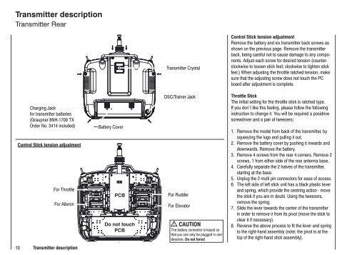
Transmitter description<br />
Transmitter Rear<br />
Charging Jack<br />
for transmitter batteries<br />
(<strong>Graupner</strong> 8NH-1700 TX<br />
Order No. 3414 included)<br />
Control Stick tension adjustment<br />
For Throttle<br />
For Aileron<br />
10 Transmitter description<br />
Battery Cover<br />
PCB<br />
Do not touch<br />
PCB<br />
Transmitter Crystal<br />
DSC/Trainer Jack<br />
For Rudder<br />
For Elevator<br />
CAUTION<br />
The battery connector is keyed so<br />
that you can only be plugged in one<br />
direction. Do not force!<br />
Control Stick tension adjustment<br />
Remove the battery and six transmitter back screws as<br />
shown on the previous page. Remove the transmitter<br />
back, being careful not to cause damage to any components.<br />
Adjust each screw for desired tension (counter-<br />
clockwise to loosen stick feel; clockwise to tighten stick<br />
feel.) When adjusting the throttle ratched tension, make<br />
sure that the adjusting screw does not touch the PC<br />
board after adjustment is complete.<br />
Throttle Stick<br />
The initial setting for the throttle stick is ratched type.<br />
If you don`t like this feeling, please follow the following<br />
instruction to change it. You will be required a posidrive<br />
screwdriver and a pair of tweezers;<br />
1. Remove the model from back of the transmitter, by<br />
squeezing the lugs and pulling it out.<br />
2. Remove the battery cover by pushing it inwards and<br />
downwards. Remove the battery.<br />
3. Remove 4 screws from the rear 4 corners. Remove 2<br />
screws, 1 from either side of the rear antenna base.<br />
4. Carefully separate the 2 halves of the transmitter,<br />
starting at the base.<br />
5. Unplug the 2 multi pin connectors for ease of access.<br />
6. The left side of left stick unit has a black plastic lever<br />
and spring, which provide the centring action - move<br />
the stick if you are in doubt. Using the tweezers,<br />
remove the spring.<br />
7. Slide the lever towards the center of the transmitter<br />
in order to remove ir from its pivot (move the stick to<br />
clear it if necessary).<br />
8. Reverse the above process to fit the lever and spring<br />
to the right-hand assembly (note; the pivot is at the<br />
top of the right-hand stick assembly).