Download - Fischer Connectors
Download - Fischer Connectors
Download - Fischer Connectors

Create successful ePaper yourself
Turn your PDF publications into a flip-book with our unique Google optimized e-Paper software.
9-5<br />
A / Z Polarity<br />
Type<br />
Pin Layout<br />
Number of Contacts<br />
Contact<br />
Termination<br />
Insulating Material<br />
Mixed High Voltage<br />
Electrical & Contact Specifications<br />
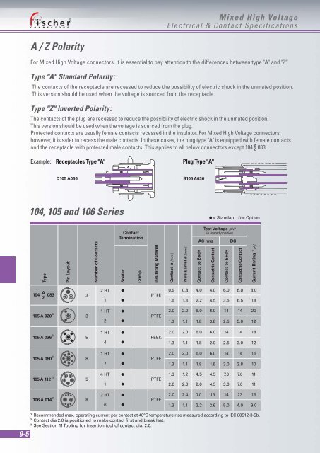
For Mixed High Voltage connectors, it is essential to pay attention to the differences between type "A" and "Z".<br />
Type "A" Standard Polarity:<br />
The contacts of the receptacle are recessed to reduce the possibility of electric shock in the unmated position.<br />
This version should be used when the voltage is sourced from the receptacle.<br />
Type "Z" Inverted Polarity:<br />
The contacts of the plug are recessed to reduce the possibility of electric shock in the unmated position.<br />
This version should be used when the voltage is sourced from the plug.<br />
Protected contacts are usually female contacts recessed in the insulator. For Mixed High Voltage connectors,<br />
however, it is safer to recess the male contacts. In these cases, the plug type "A" is equipped with female contacts<br />
and the receptacle with protected male contacts. This applies to all below connectors except 104 083.<br />
A Z<br />
Example: Receptacles Type "A" Plug Type "A"<br />
104 A 083<br />
Z<br />
105 A 020 3)<br />
105 A 036 3)<br />
105 A 060 3)<br />
105 A 112 2) 5<br />
106 A 014 3)<br />
D105 A036 S105 A036<br />
104, 105 and 106 Series<br />
3<br />
3<br />
5<br />
8<br />
8<br />
2 HT<br />
1<br />
1 HT<br />
2<br />
1 HT<br />
4<br />
1 HT<br />
7<br />
4 HT<br />
1<br />
2 HT<br />
6<br />
Solder<br />
●<br />
●<br />
●<br />
●<br />
●<br />
●<br />
●<br />
●<br />
●<br />
●<br />
●<br />
●<br />
Crimp<br />
PTFE<br />
PTFE<br />
PEEK<br />
PTFE<br />
PTFE<br />
PTFE<br />
Contact ø [mm]<br />
Wire Barrel ø [mm]<br />
Test Voltage [KV]<br />
in mated position<br />
AC rms DC<br />
Contact to Body<br />
● = Standard ❍ = Option<br />
Contact to Contact<br />
Contact to Body<br />
Contact to Contact<br />
Current Rating 1) [A]<br />
0.9 0.8 4.0 4.0 6.0 6.0 8.0<br />
1.6 1.8 2.2 4.5 3.5 6.5 18<br />
2.0 2.0 6.0 6.0 14 14 20<br />
1.3 1.1 1.8 3.8 2.5 5.0 12<br />
2.0 2.0 6.0 6.0 14 14 18<br />
1.3 1.1 1.8 2.0 2.5 3.0 12<br />
2.0 2.0 6.0 6.0 14 14 16<br />
1.3 1.1 1.8 1.6 3.0 2.8 10<br />
1.3 1.2 4.5 4.5 7.0 7.0 11<br />
2.0 2.0 2.0 4.5 3.0 7.0 11<br />
2.0 2.4 7.0 15 14 23 16<br />
1.3 1.1 2.2 2.6 5.0 4.0 9.0<br />
1) Recommended max. operating current per contact at 40°C temperature rise measured according to IEC 60512-3-5b.<br />
2) Contact dia 2.0 is positioned to make contact first and break last.<br />
3) See Section 11 Tooling for insertion tool of contact dia. 2.0.